7. Electronics design
Group assignment:
- Use the test equipment in our lab to observe the operation of a microcontroller circuit board.
Individual assignment:
-
Redraw an echo hello-world board
-
Add at least a button and LED with current-limiting resistor
-
Check the design rules, make it, and test it
Group assignment
Our group assignment can be found here.
Individual assignment
STEP 1
I used Autodesk Eagle to design my ATTINY412 echo hello-world board. First step was to download and add following Eagle libraries to Libraries folder; Documents >> EAGLE >> libraries:
STEP 2 On Eagle control panel I chose Options >> Directiories and added the path to Eagle libraries to Libraries box.
Schematic
STEP 1
I created a folder named echohello to my Eagle projects directory. I activated the project on Eagle control panel by clicking the grey dot next to echohello to turn it green. Next I right clicked on echohello project and chose New >> Schematic.
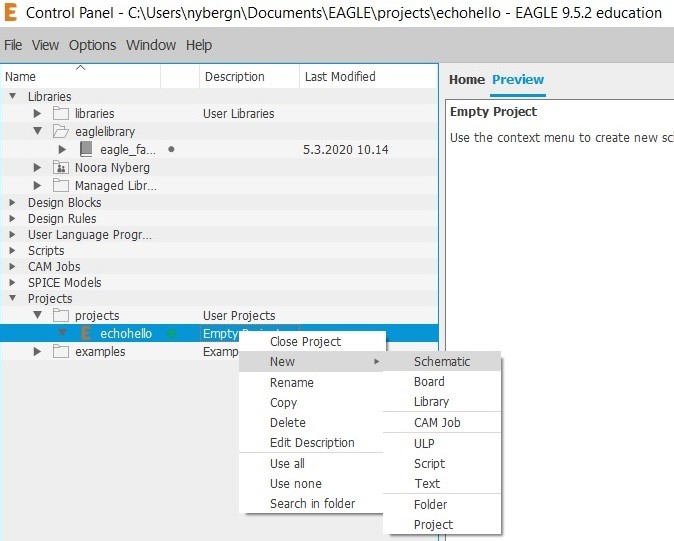
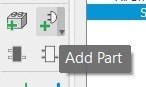
STEP 2
On schematic tool bar I clicked Add Part.
I chose ATTINY412-SSF and added it to the canvas. All components required for the echohello board are
-
ATTINY412-SSF
-
CONN_06_FTDI-SMD-HEADER
-
CAP_UNPOLARIZEDFAB
-
CONN_03SMD_RA_MALE
-
GND
-
VCC
-
LEDFAB1206
-
SW_SWITCH_TACTILE_6MM6MM
-
R1206FAB(499Ω)
-
R1206FAB(10KΩ)
-
GND
-
VCC
STEP 3
I moved and rotated the components to appropriate position using move and rotate tools. With Group tool one can move or rotate multiple components together.

STEP 4
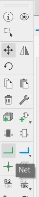
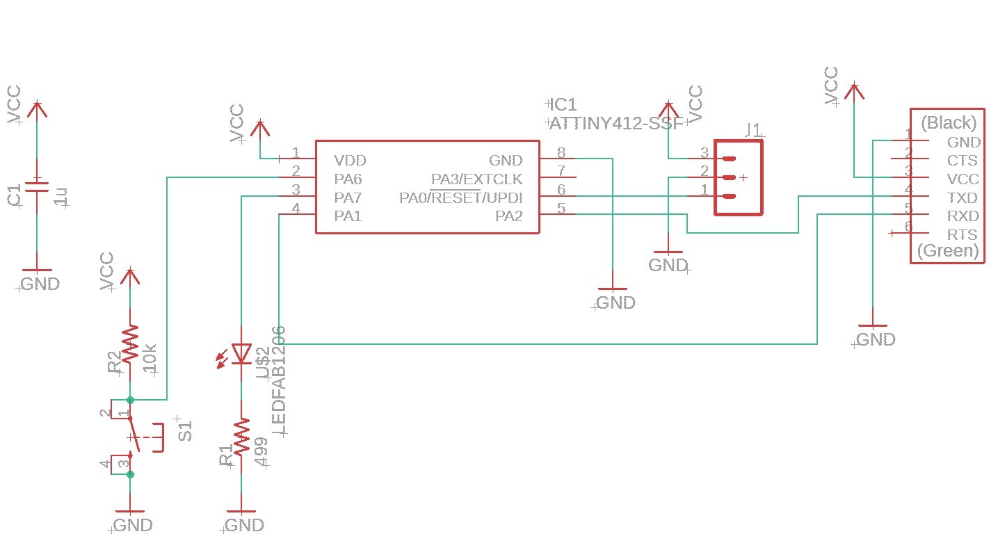
Next I connected the components using net tool.
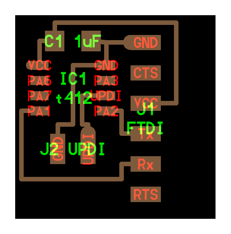
The finished schematic:
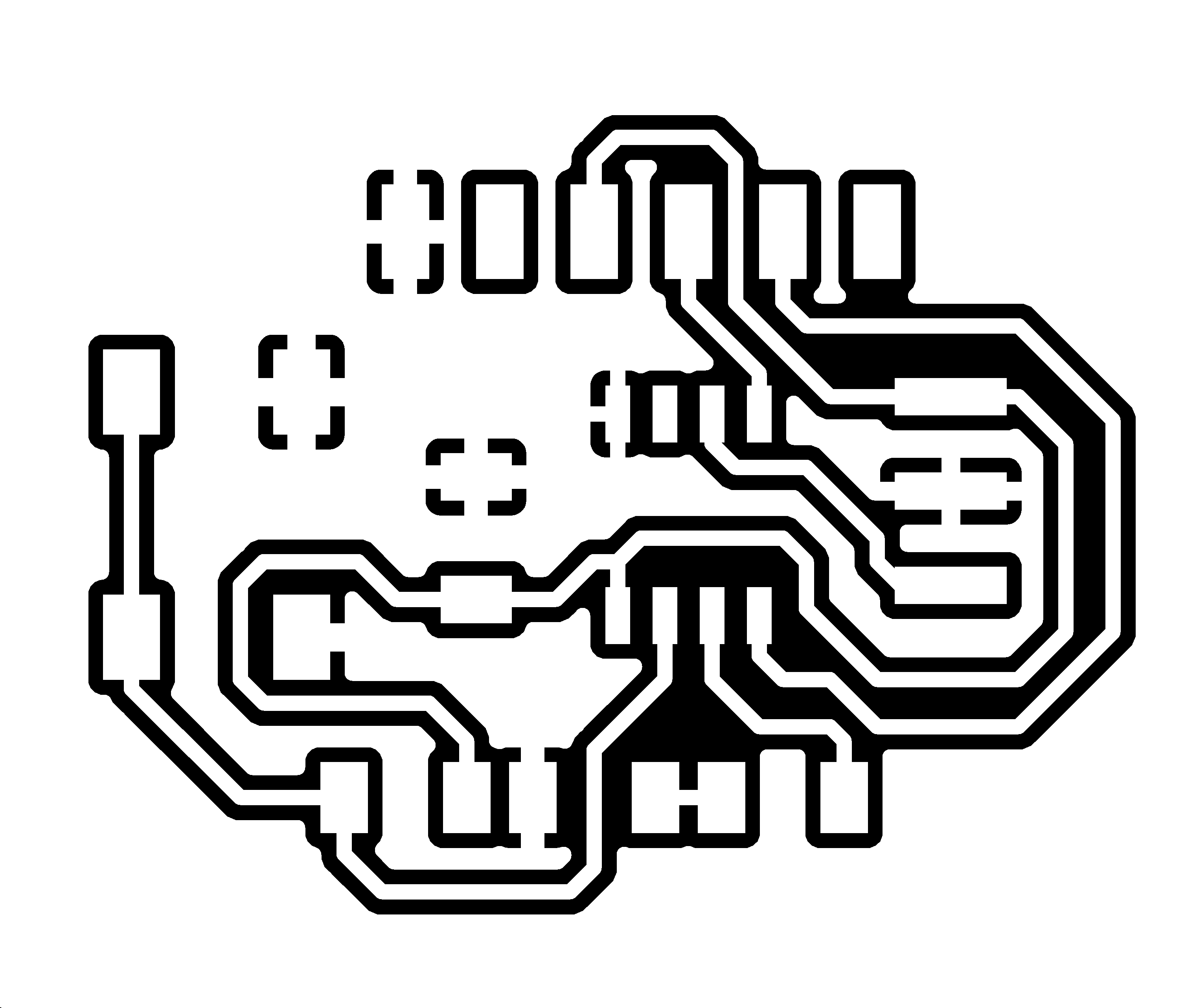
Board Layout
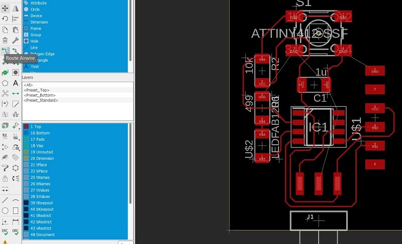
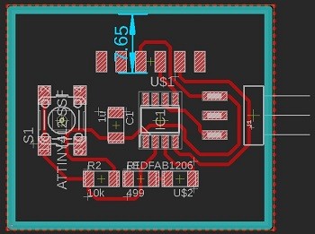
STEP 1
The board layout was done using board layout editor. I used move and rotate tools to arrange components to proper places and connected them with Route Airwire tool.
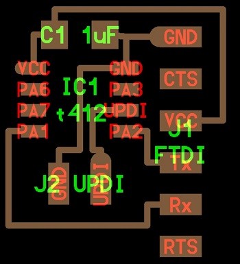
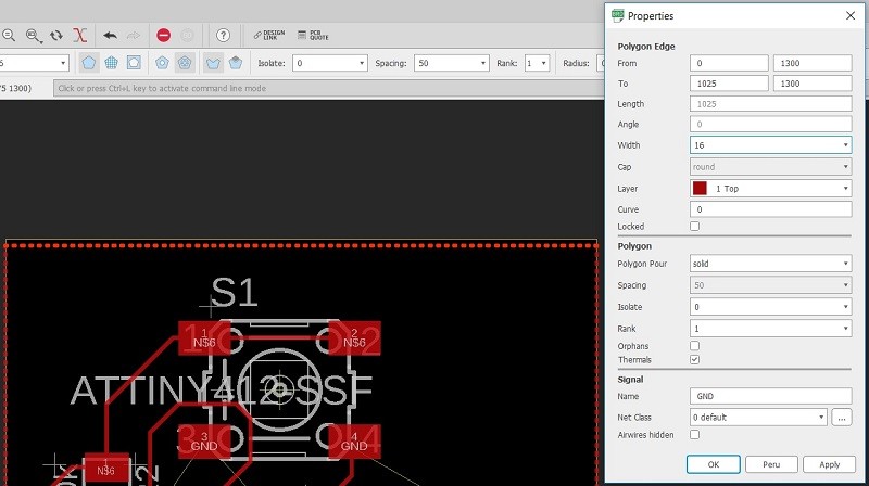
Step 2
Next I created ground using Polygon tool around the board and named it GND.
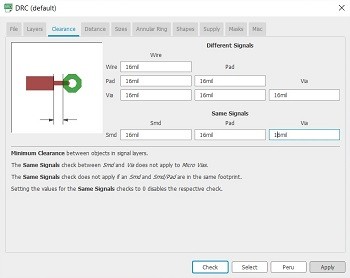
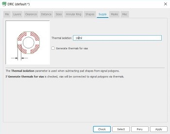
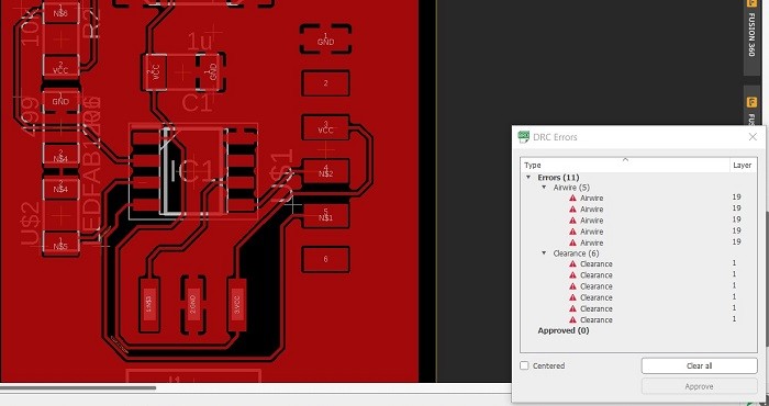
STEP 3
I defined the Design Rules Check (DRC) parameters to 16 mils and fixed airwires and clearence issues by moving traces.
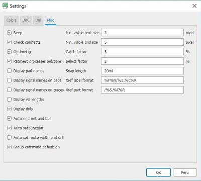
STEP 4
I removed the text from traces and pads by removing the taps shown in the picture in BRD Settings Mics.
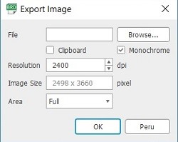
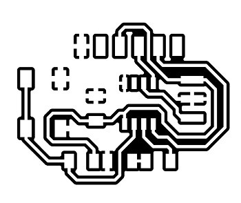
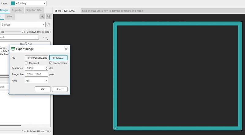
STEP 5
I exported the traces PNG image using 2400 dpi resolution and choosing Monochrome.
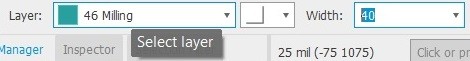
STEP 6
Next I draw the outline using Line tool and setting the working layer to Milling and width to 40 mils.
STEP 7
I used Dimension tool to reserve enough space for the 6 pin header.
STEP 8
I exported the outline PNG image with working layer Milling active the same way as exporting the traces.

Creating gcode file
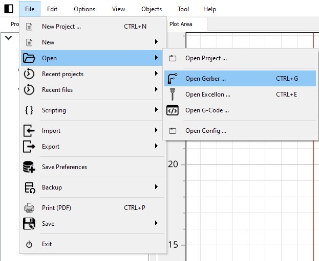
Step 1
I used FlatCAM to make the gcode for our Excitech CNC router. I exported .gbr file from Eagle and opened it in FlatCAM.
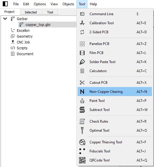
Step 2
I activated the gbr file by clicking it and chose Non-Copper Clearing (ncc) from Tool menu.
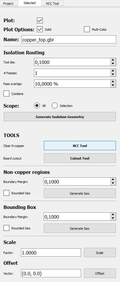
Step 3
To define the tool used I chose NCC Tool in Selected tab.
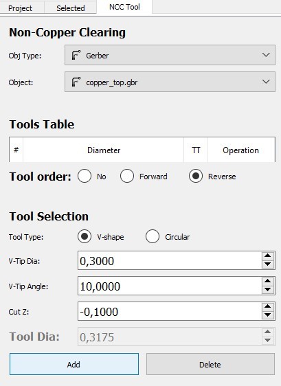
Step 4
In NCC tool tab I chose V-shape milling bit with V-tip dia 0.3 mm, V-tip Angle 10° and Cut Z -0.1 mm. I clicked Add to add tool selection to tool table.
In Paramaters I changed Method to Straight lines and unselected Connect and Contour boxes. Then I clicked Generate Geometry.
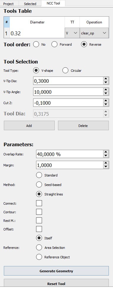
After couple of seconds the software had greated toolpath for the milling process.
Step 5
Next I clicked Generate CNCJob object in Selected tab to generate the gcode file.
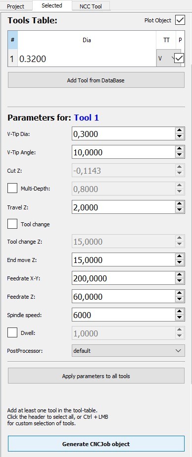
I clicked Save CNC Code to save the generated gcode to my computer.
After these steps I had all files showing in the Project tab (.gbr file, tool geometry file and .nc file)
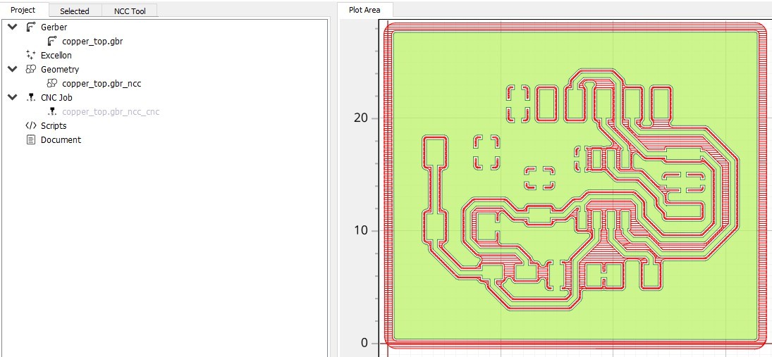
I copied the gcode file to flash drive to use it with the milling machine.
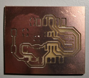
Milling and soldering
The process with the milling machine was exactly same as in Computer controlled machining week. I used two sided tape to attach the board to the plywood base.
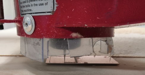
I cut the milled board using scroll saw by following milled outline profile.
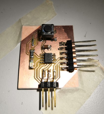
The soldering was done in the same way as in week 5.
Testing the board
Next I tested the board using Blink example code in Arduino IDE. LED pin number is 1 in my board.
// the setup function runs once when you press reset or power the board
void setup() {
  // initialize LED pin 1 as an output.
  pinMode(1, OUTPUT);
}

// the loop function runs over and over again forever
void loop() {
  digitalWrite(1, HIGH);   // turn the LED on (HIGH is the voltage level)
  delay(1000);                       // wait for a second
  digitalWrite(1, LOW);    // turn the LED off by making the voltage LOW
  delay(1000);                       // wait for a second
}
From tools tab I chose
-
Board: ATTiny 412/402/212/202
-
Port: COM4 (in my computer)
-
Programmer: jtag2updi(megaTinyCore)
The programmer used is the one made in week 5. I connected the programmer to my computer and to my freshly made board.
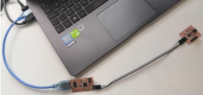
I clicked Upload and I was happy to see that the board was working!
Reflection
Designin the board seemed a bit difficult at first but luckily we got good step by step instructions to that. Since I was not able to get to Oulu to mill manufacture my board I had to do it in our Fab Lab in Tampere. They use Excitech CNC router also to mill boards so that is what I had to learn also. After figuring out how to create the gcode files for the router using FlatCAM the end process went very smoothly. The calibration was super simple to do and the end result was flawless.