4. Computer controlled cutting
Group assignment:
- Characterize your lasercutter’s focus, power, speed, rate, kerf, and joint clearance
Individual assignment:
-
Cut something on the vinylcutter
-
Design, lasercut, and document a parametric construction kit, accounting for the lasercutter kerf, which can be assembled in multiple ways
Group assignment
At this week’s local lecture I learned basic laser cutting operation procedure by characterizing lasercutter’s focus, power, speed, rate, kerf, and joint clearance.
By adjusting speed, power and frequency one can cut or engrave specific material. More about group assignment and characterizing these variables here.
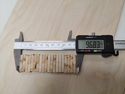
Since I was working in Fablab Tampere I characterized our laser cutter’s (Trotec) kerf by myself with ladder kerf test. I got the kerf value of
(Total length of original drawing – Actual length after cutting)/20
(100mm - 96.83mm)/20 = 0.1585 mm,
which was very close to the one I used when I managed to get a good fit with construction kit parts (0.15 mm)
Individual assignment
Designing parametric construction kit
After experimenting with lasercutter and characterizing kerf I started to sketch the construction kit. Since I’m not very familiar with CAD softwares and I had to accomplish both this and previous week assignments I decided to sketch something fairly simple.
I used Fusion 360 for modeling the construction kit.
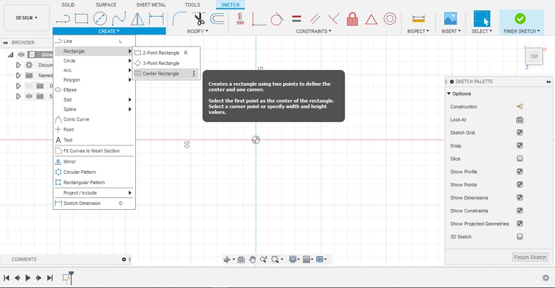
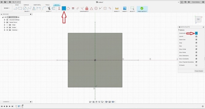
STEP1: I started by creating sketch and creating 50mmx50mm center rectangle. create sketch (on xz plane), then create >> rectangle >> center rectangle.
STEP2: Next I created coincident lines with center axes with construction tool activated to help me design the slots. activate construction (on the sketch palette) >> create lines on axes, then coincident >> click on origo and line to be coincident
STEP3: I used extrude tool to make a 3mm high object. Next I made one center rectangle on each side of the first sketch with the center point being in the cross point of an axis and a side.
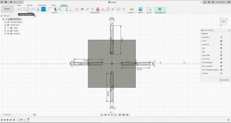
Here I used parameters to define the dimensions of the object. modify >> change parameters
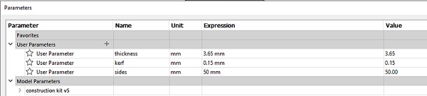
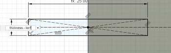
I used parameters thickness and kerf to define the slot width as ‘thickness - kerf ‘.
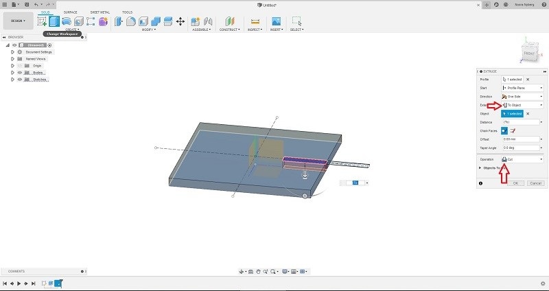
STEP4: I extruded every slot from top plane to bottom plane (to object) using cut operation. extrude >> click on top plane >> extent (on extrude palette) >> to object >> click on bottom plane
STEP5: I used chamfer tool with 3mm distance to cut the conrners of the slots to make it easier to assemble parts together. modify >> chamfer
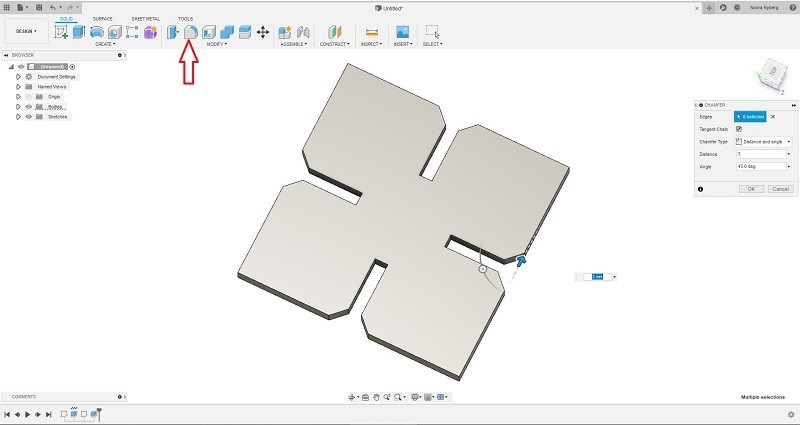
I also used fillet tool to round the corners. modify >> fillet
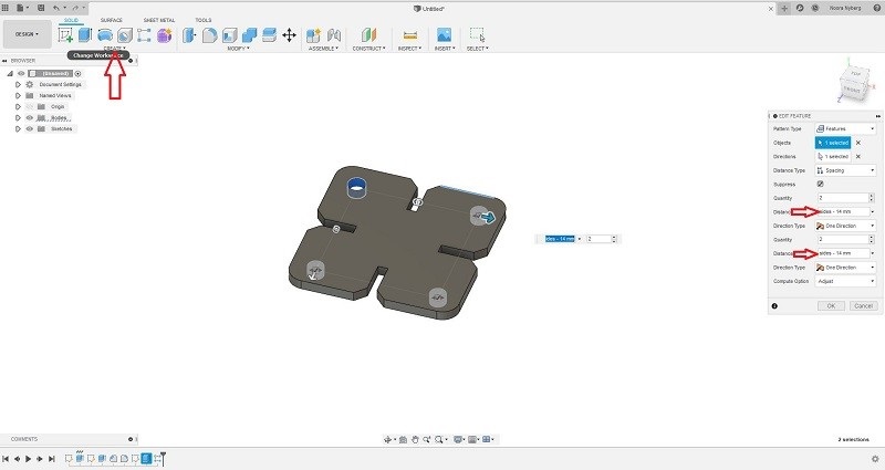
STEP6: I also wanted to create holes on each quarter to get some practice with Fusion. I created center diameter cirle sketch with 5mm diameter on top left quarter. I used rectangular pattern to copy a hole on each quarter. I defined distance between holes to be (sides - 14 mm) with sides being parameter of object’s sides (50mm). This means that distance between center points of cirles is (sides - 14mm). create sketch on top plane >> center diameter cirle, then extrude >> to object (bottom plane), next create >> pattern >> rectangular pattern, then choose patterns type: features >> click on cirlce >> select directions on edit feature palette >> click on x axis >> pull the arrow to the right (distance: sides - 14). Do the same on z axis.
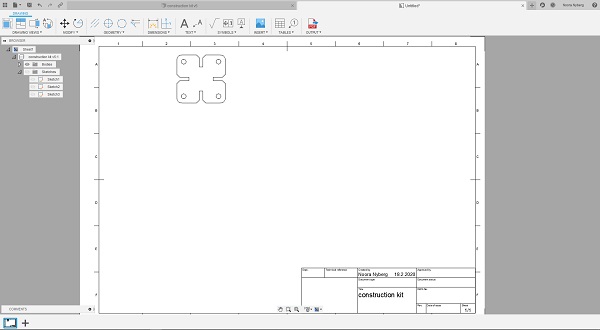
STEP7: I used drawing workspace to create a pdf file from the model. design >> drawing >> from design
I used Adobe Illustrator to modify the pdf file as described in the next section so it can be laser cut. In our Fablab it is recommended to use Adobe Illustrator to modify and print (send file to laser cutter) the file, so I decided to use that at least for now instead of Inkscape.
Laser cutting the construction kit
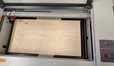
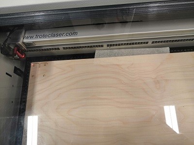
STEP1: I adjusted laser cutter’s bed level with leveling tool to adjust the focus of the laser. Bed level is adjusted using arrow buttons on the machine’s control panel. When leveling tool falls of from the holder the laser is on focus.
STEP 2: I opened the pdf file with Adobe Illustrator and changed line width to be 0.001mm as recommended. I made a copy of the model so I could get two parts of the kit to check if they fit together properly. Next I printed the file (sent file to job control, which is used to send the file to the laser cutter).
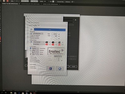
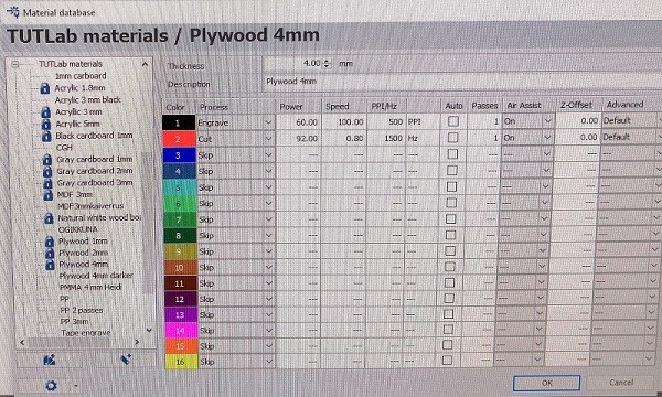
The speed was 0.80, power 92 and frequency 1500Hz as default settings for 4mm plywood. The material I used was plywood with 3.65mm thickness but I didn’t change laser cutter parameters for that.
After checking the placement of the cut using arrows on the control panel, I pressed play on the job control and laser cutter started to do it’s work.
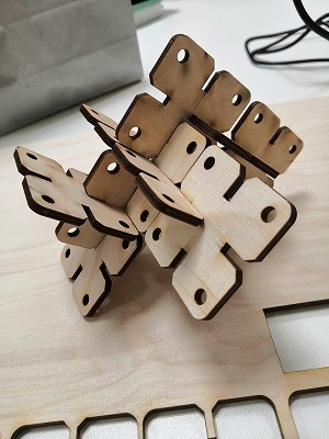
STEP3: I had to do some adjustments to my model’s material thickness parameter since I had forgotten to change it to mach the actual material thickness. After two test cuts I managed to get a kit with a good fit. I cut eight more parts to make a proper kit.
Safety instructions for working with laser cutter
-
You are not allowed to leave the laser cutter unsupervised even for one moment.
-
When you cut with laser cutter, you have to wait one minute or so to let the exhaust pull away the gases before you open the lid!
If there is a fire while laser cutting:
-
First, you open the lid and then the laser stops working.
-
If there is still fire, cover the place with the ‘fire blanket’ to smother the fire.
-
If it is possible, bring the material out of the machine and then if you failed to stop the fire with the fire blanket, then use the fire extinguisher.
-
At the end, if there is too much fire and you failed to stop the fire after trying the above mentioned steps, use the fire extinguisher directly inside the laser cutter.
Cutting with vinyl cutter
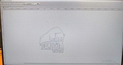
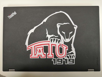
I decided to cut our swimming club’s logo using vinyl.
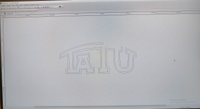
STEP1: I started by slightly modifying the pdf logo file with Adobe Illustrator: I deleted some extra lines to make it possible to cut. The file was a pdf vector file and the picture was made from separate lines so I didn’t have to do anything else but to delete some extra (double) lines on top each other by clicking on top of the unwanted line and clicking delete button.


STEP2: After modifying the file I opened it with vinyl cutter software Summa Winplot. I didn’t have to do any adjustments with the software since in this cutter software the thickness of the line does not matter. All the lines are cut. Vinyl cutter will position files to the material, so the exact size of the artboard is not important, only the measurements in the picture itself.
STEP3: The model of the vinyl cutter machine used is SummaCut D60R. I lowered the leaver in the right-hand side of the cutter and inserted the material to left-hand side of the cutter. I made sure that the material was placed straight. I moved the right pinchroller to the position where it is over the material. Pinchroller has to be placed to place shown with arrows in the machine. Placement of the pinchroller determinises the area where cutter works. After this I lifted the leaver up.
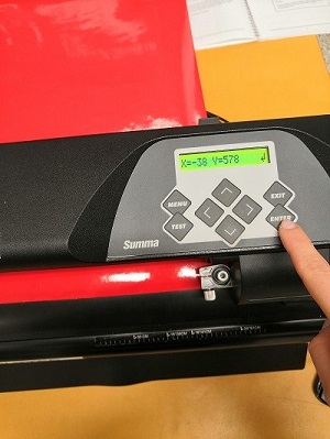
Next the vinyl cutter measured the dimensions of the vinyl and then I adjusted the starting point of the cut with arrow buttons shown in the next picture to reduce wasted material. After moving the material, I pressed enter to go back to mode where computer can access the printer.
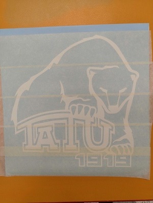
STEP4 In the Summa Winplot I selected Output >> Send to cutter. I pressed OK and watched the vinyl cutter start cutting. I cut the whole file with white vinyl and TATU text with red vinyl. For cutting only the text I deleted everything else on the file using Summa Winplot.
STEP3: After the cut I removed all extra vinyl using tweezers so that only the actual logo remained. Then I put painter’s tape on the vinyl side and removed the backside.
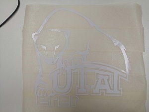
I repeated the same process with red TATU text.
STEP4: Finally I sticked up the sticker on my laptop.
What I learned
I learned how to model objects using parameters and how convenient it is to modify the model with these parameters. From now on I try to model everything like this.
I also learned a lot about the process involved in using laser cutter. Measuring the kerf and to take it into account when modelling an object for laser cutting was new to me but now I’m familiar with that aspect. The group assignment was very instructive and I learned how to take the material used into account and how to adjust parameters when using a laser cutter.
I was somewhat familiar with the process involved in using the vinyl cutter but there were also new things I learned; editing a file using Adobe Illustrator and how to apply the cut sticker onto wanted surface.
Problems
I did’t face any major problems this weeks since I got help from our Fablab staff with modeling and using the machines. I had to do some adjustment with the construction kit to make the parts fit properly together but that was pretty much it. At first I was’t sure how to add files to the website, but I think I’ve found a way that works. I add the files to my image folder and link them like this: [TaTU1919logo.pdf] (../images/week04/TaTU1919logo.pdf), for example.