12. Output devices
Group assignment:
- Measure the power consumption of an output device
Individual assignment:
- Add an output device to a microcontroller board you’ve designed, and program it to do something
Group assignment
Our group assignment can be found here.
Individual assignment
Tinkercad simulation
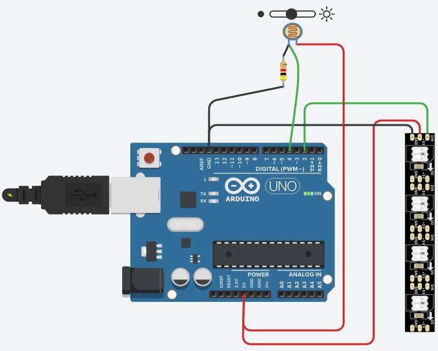
I used Tinkercad to test how a board with photoresistor and neopixels works.
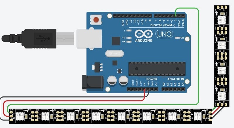
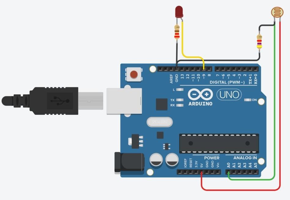
There is a neopixel starter board that I used as a reference how to build a board with neopixels. I also checked a board from Photoresistor Circuit Lesson (input devices week)
Neopixel starter board and Photoresistor board:
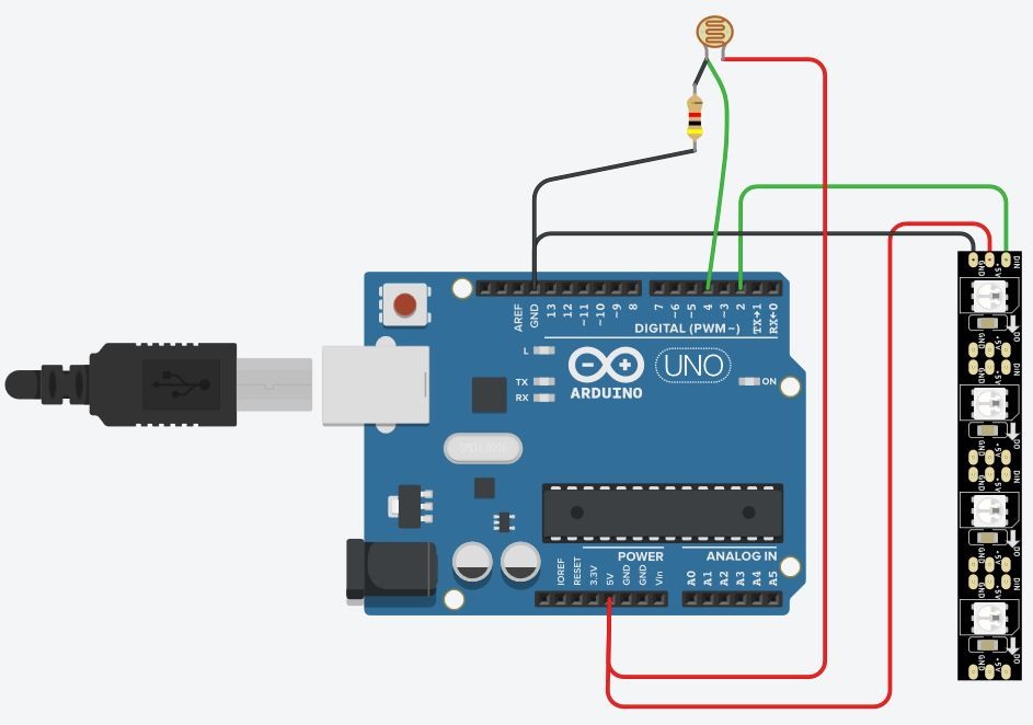
By combining these two boards I made following circuit:

I googled “arduino neopixel photoresistor” to find a code for contolling the board. I found following, and modified it to mach my board.
#include <Adafruit_NeoPixel.h>

#define NUM_LEDS 8  // This many NeoPixels...
#define LED_PIN  1  // are connected to this DIGITAL pin #
#define SENSOR   2  // Light sensor to this DIGITAL pin #

Adafruit_NeoPixel strip(NUM_LEDS, LED_PIN);

void setup() {
  strip.begin();
  strip.show();                  // Initialize all pixels to 'off'
  pinMode(SENSOR, INPUT_PULLUP); // Enable pull-up resistor on sensor pin
}

void loop() {
  // The LDR is being used as a digital (binary) sensor, so it must be
  // COMPLETELY dark to turn it off, your finger is not opaque enough!
  if(!digitalRead(SENSOR)) {                 // Sensor exposed to light?
    colorWipe(strip.Color(255, 0, 255), 50); // Animate purple
  } else {                                   // else sensor is dark
    colorWipe(strip.Color(0, 0, 0), 50);     // Animate off
  }
  delay(2); // Pause 2 ms before repeating
}

// Fill pixels one after the other with a color
void colorWipe(uint32_t c, uint8_t wait) {
  for(uint16_t i=0; i<strip.numPixels(); i++) {
    strip.setPixelColor(i, c);
    strip.show();
    delay(wait);
  }
}
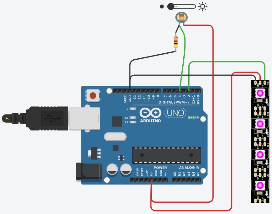
By reading through the code I realised that I had connected the photoresistor to analog input A0 and according to the code it should be connected to a digital pin. I modified the circuit by connecting the photoresistor to digital pin 4.
I modified the code by changig NUM_LEDS to 4, LED_PIN to 2 and SENSOR to 4.
#define NUM_LEDS 4  // This many NeoPixels...
#define LED_PIN  2  // are connected to this DIGITAL pin #
#define SENSOR   4  // Light sensor to this DIGITAL pin #
I tested the circuit by clicking the Start Simulation button and it worked: with very little to no light the LEDs turn on and by adding more light they turn off.
Final project board
I have an ultrasonic distance sensor which I’m going to use as an input. The data received from distance sensor is used to control neopixel strip (output) in my final project.
I’m desining my board based on Arduino board. First, I tested ultrasonic - neopixel wiring and code with Tinkercad.
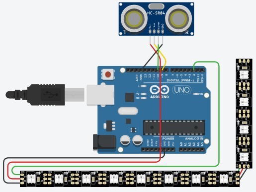
I designed the system by combining neopixel and ultrasonic starter demos. I combined input devices week code with Tinkercad neopixel starter demo code and tested the code with my Tinkercad Arduino circuit.
When combining the ultrasonic distance sensor with neopixel, I have to map sensor values
to be able to control the led strip colour based on the distance. I added variable ledValue to see mapped sensor values that are used to control the neopixel and the command to
print its value to serial monitor.
I used it also in for loop that controls the neopixel colour. The colour is
determined so that the higher the ledValue is, the more it “pulls back” green and blue colours which makes the actual colour brighter.
I wanted the distance that starts to change the colour to be 1,5 m so I set map variables to ledValue = map(distance, 0, 150, 0, 255).
I saw from serial monitor that this made it possible to ledValue to be negative. I didn’t want that, so I added if (ledValue < 0) {ledValue = 0;} statement.
// NeoPixel Ring simple sketch (c) 2013 Shae Erisson
// released under the GPLv3 license to match the rest of the AdaFruit NeoPixel library

#include <Adafruit_NeoPixel.h>
#ifdef __AVR__
  #include <avr/power.h>
#endif

// Which pin on the Arduino is connected to the NeoPixels?
// On a Trinket or Gemma we suggest changing this to 1
#define PIN            2

// How many NeoPixels are attached to the Arduino?
#define NUMPIXELS      12

// defines ultrasonic pins numbers
const int trigPin = 9;
const int echoPin = 10;

// defines variables
long duration;
int distance;
int ledValue;

// When we setup the NeoPixel library, we tell it how many pixels, and which pin to use to send signals.
// Note that for older NeoPixel strips you might need to change the third parameter--see the strandtest
// example for more information on possible values.
Adafruit_NeoPixel pixels = Adafruit_NeoPixel(NUMPIXELS, PIN, NEO_RGB + NEO_KHZ800);

int delayval = 83; // delay for half a second

void setup()
{
  pinMode(trigPin, OUTPUT); // Sets the trigPin as an Output
  pinMode(echoPin, INPUT); // Sets the echoPin as an Input
  Serial.begin(9600); // Starts the serial communication
  pixels.begin(); // This initializes the NeoPixel library.
  pinMode(2, OUTPUT);
}

void loop()
{
  // Clears the trigPin
  digitalWrite(trigPin, LOW);
  delayMicroseconds(2);

  // Sets the trigPin on HIGH state for 10 micro seconds
  digitalWrite(trigPin, HIGH);
  delayMicroseconds(10);
  digitalWrite(trigPin, LOW);

  // Reads the echoPin, returns the sound wave travel time in microseconds
  duration = pulseIn(echoPin, HIGH);

  // Calculating the distance
  distance = duration*0.034/2;

   // map the sensor reading to a range for the LED
  ledValue = map(distance, 0, 150, 0, 255);
  if (ledValue < 0) {
    ledValue = 0;
  }
  digitalWrite(2, ledValue);

  // Prints the distance on the Serial Monitor to know its range
  Serial.print("Distance: ");
  Serial.println(distance);

  // Prints the LED value on the Serial Monitor to know its range
  Serial.print("LED Value: ");
  Serial.println(ledValue);


  for(int i=0;i<NUMPIXELS;i++){

    // pixels.Color takes RGB values, from 0,0,0 up to 255,255,255
    pixels.setPixelColor(i, pixels.Color(ledValue,255,ledValue)); // Colour based sensor value.

    pixels.show(); // This sends the updated pixel color to the hardware.
    pixels.show(); // This sends the updated pixel color to the hardware.

    delay(delayval); // Delay for a period of time (in milliseconds).

   // For a set of NeoPixels the first NeoPixel is 0, second is 1, all the way up to the count of pixels minus one.

  }
}
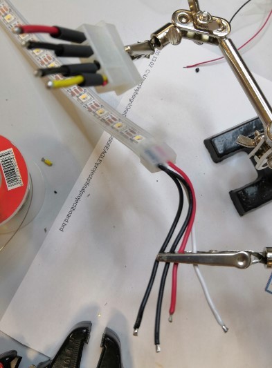
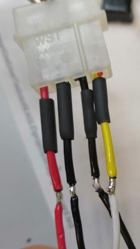
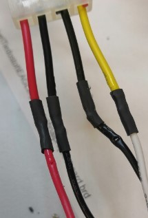
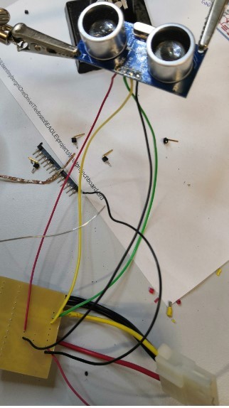
Now the code seemed to be working the way I wanted in Tinkercad at least, so it was time to test it with my actual Arduino board. I made the wiring based on Tinkercad simulation and soldered wires to ultasonic sensor.
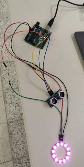
I had to make this kind of wiring from vcc to power both ultrasonic sensor and neopixel.

I downloaded the code to my Arduino using Arduino IDE. It worked just the way I wanted but the first led was blinking green.
I tried to change delayval variable to see if that woul do anything. It did not. Then I tried to power my Arduino with USB power hub and that did not have
any effect either. Changing the colour in the code from red to green did help the way that you couln’t see the problem as clearly. But I didn’t want to settle just
to change the colour. I wanted to try if it could be fixed. After some googleing I was able to find out that other people have had the same issue
without any explanation why the neopixel ring does this. It could be fixed by adding an extra pixels.show(); // This sends the updated pixel color to the hardware.
statement. The led was still blinking very slighlty, if you looked closely it can be seen. I tried addig another copy of that statement
but it didn’t have any effect. I decided that since it really was not notable anymore I will go with that.
After this it really felt like a victory that the whole system was working!
Next thing to do was to design the board using Eagle.
Board design
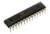
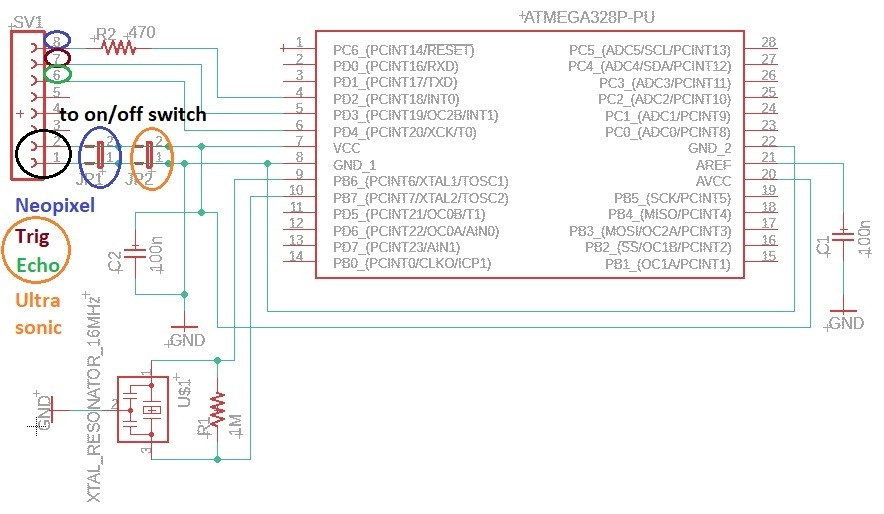
I designed the actual board based on Arduino board with help of an article about Understanding Arduino UNO Hardware Design. I am using a ATmega328P in 28-pin narrow dual in-line package since we have those in our lab and I can use my Arduino to program the microcontroller.
I used article’s microcontroller schematics picture to make my own simplified schematic (input and output on the same board). I downloaded ATMEGA328P-PU - Microchip PCB Footprints and Schematic Symbols and added it to my Eagle library. I used my electronics design page documentation to remind me how to do schematics and board design in Eagle.
The components I used are
-
ATMEGA328P-PU
-
28 pin socket
-
XTAL_RESONATOR_16MHz
-
Resistor 1 MΩ
-
Resistor 470 Ω
-
2 x 100 nF
-
8 pin connector
-
2 x 2 pin jumper
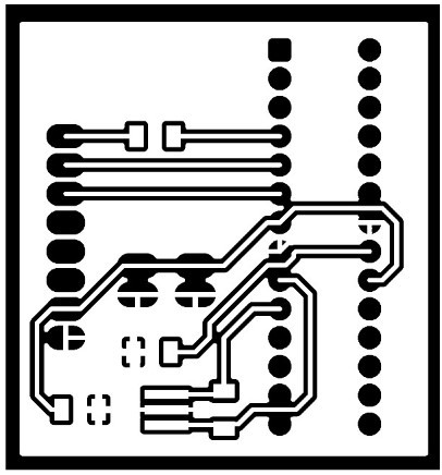
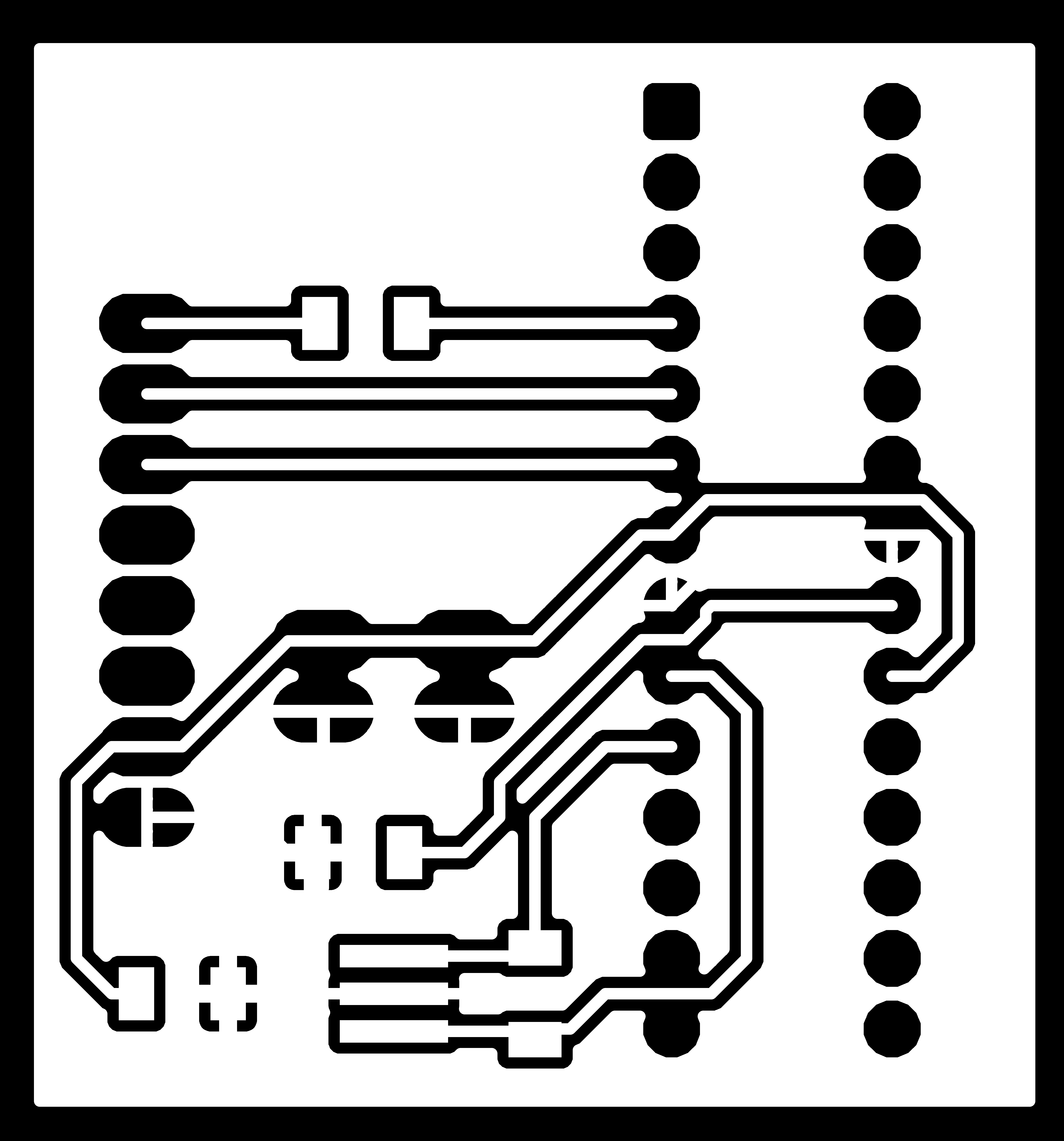
I ended up with board like this:
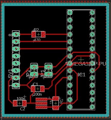
I exported png images of the board same way as in the electronicsdesign week.
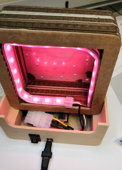
The board should work the same way as my Arduino board. The board is powered so that the 8 pin connector is going to be connected to on/off switch with wires and the switch is connected to power jack. Both on/off switch and power jack have their place in the lamp stand.
Milling and soldering
I used FlatCAM to make the gcode for our Excitech CNC router. The process was same as in week 7. I exported .gbr and .xln files from Eagle and opened them in FlatCAM.
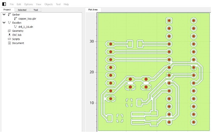
I used V-milling bit (V-tip dia 0.3 mm, V-tip Angle 10° and Cut Z -0.1 mm) to mill the traces and outline profile and 0.7mm tool to drill through board holes.
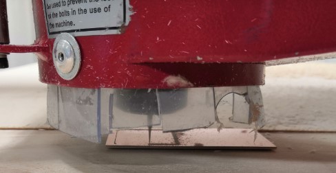
After creating the gcode files the process with milling machine was excactly the same as in Computer controlled machining week. I used two sided tape to attach the board to the plywood base.
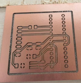
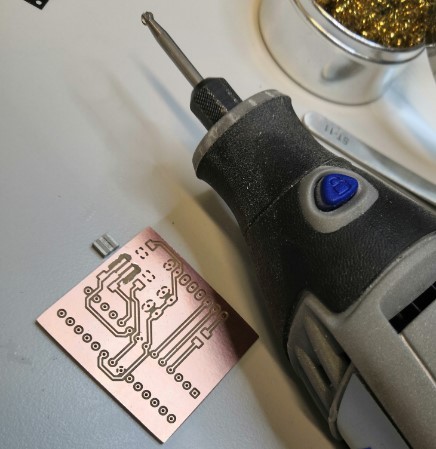
I cut the milled board using scroll saw by following milled outline profile.
I used hand mill to have wider gap for the XTAL_RESONATOR_16MHz since it was pretty tight fit on the original board.
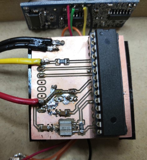
I soldered all the components to the board. It was not as smooth process as in the first time in electronics production week but I did manage to solder all the parts finally. I made a connector for neopixel wiring to make the final assembly of the lamp easier.
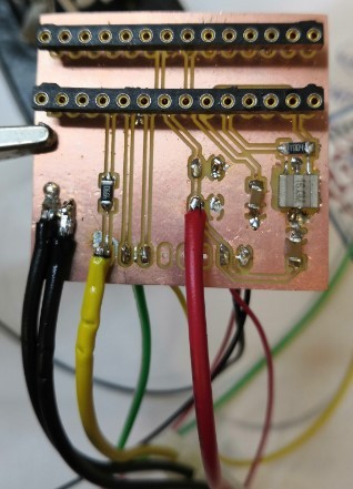
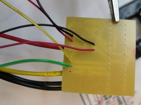
Neopixel wires were very thick and I had some problems soldering them. I finally ended up making a jump wire to have power connected close to side of the board and soldered gnd wires to board ground.
Testing
After the board was ready it was time to test if it works as nicely as with Arduino board. I changed LED number to be 20 instead of 12 as in the testing neopixel ring. I used my Arduino board to program the microcontroller and moved the programmed microcontroller to my own board by attaching it to my board’s socket. The board did not work so there was something wrong with my board. I double checked that my pin order was correct in the code and found out that I had made a mistake there.
I changed
// defines ultrasonic pins numbers
const int trigPin = 9;
const int echoPin = 10;
to
// defines ultrasonic pins numbers
const int trigPin = 3;
const int echoPin = 4;
to mach my actual pin numbers.
Now the LED strip was turned on but not the way I wanted. It had red, green and blue leds alternating
and it did not talk with my sensor data. I tried to solve the problem by checking with oscilloscope
if I could find an explanation there but I was not able find anything that could be fixed.
Then I realized that my neopixel strip was different model than the neopixel ring I had tested the code with.
After some googleing I found out that with my neopixel strip I have to modify the original code Adafruit_NeoPixel pixels = Adafruit_NeoPixel(NUMPIXELS, PIN, NEO_RGB + NEO_KHZ800)
by changing NEO_RGB into NEO_RGBW.
After chaning that part of the code the board was finally working as it should!
Reflection
During the design process of my input/output board I learned how to read and map sensor data (ultrasonic distance sensor) and how to use the data sensed by a sensor to control an output device (neopixel strip). I made a mistake at first in defining sensor pin numbers and I also had to do some debugging with neopixel strip control. I think it was very useful to test my board system in Tinkercad to have an idea about the code and wiring. I was able to design my system’s main funcions, wiring and coding there and with quite a small modifications I was able to build my own system from scratch.