8. Computer controlled machining
Group assignment:
- Test runout, alignment, speeds, feeds, and toolpaths for your machine
Individual assignment:
- Make (design+mill+assemble) something big
Group assignment
Our group assignment can be found here.
Individual assignment
Designing the box
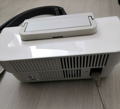
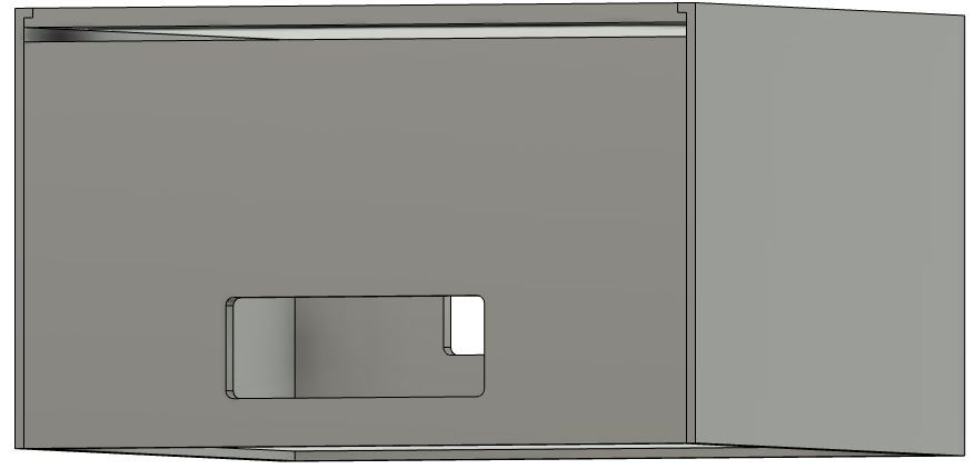
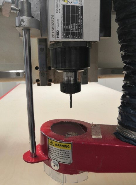
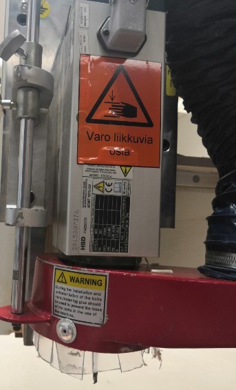
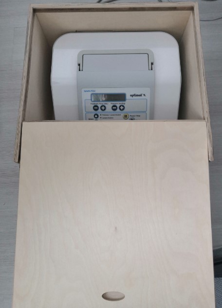
I decided to make a sound insulation box for a compression machine compressor that I have since it makes a pretty loud noice when used.
The compressor machine:
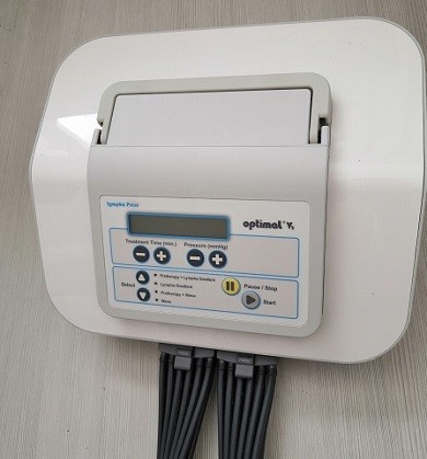
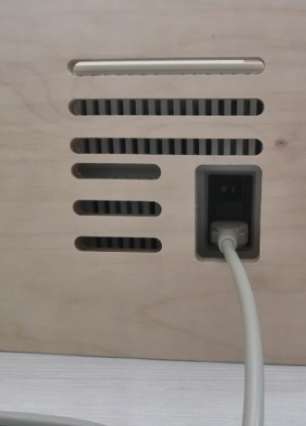
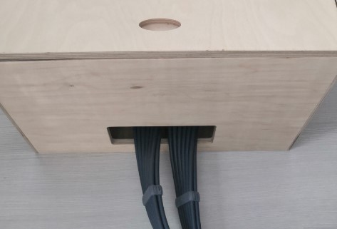
I needed to design a box that has slots for the pressure hoses, cord and vent.
Step 1
I used Fusion 360 to design the box. I have made one box before (in week 6 assignment). I have explained there more in details how to use the tools I’m also using this week.
I used parameters to define box dimensions.
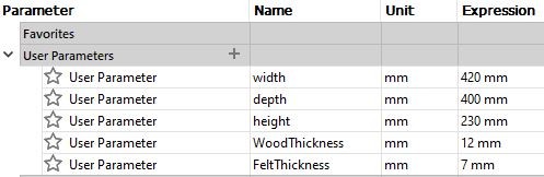
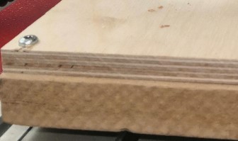
I’m using 12 mm plywood and 7 mm felt as sound insulator. Width, depth and height are machine dimensions + some extra space to be able to put the machine into the box and to take it out if necessary. The dimensions in the design are calculated taken into account the plywood and felt thickness. The bottom plane dimensions are for example as depth + WoodThickness + 2xFeltThickness and width + WoodThickness + 2xFeltThickness. The joint depth on each side is WoodThickness/2.
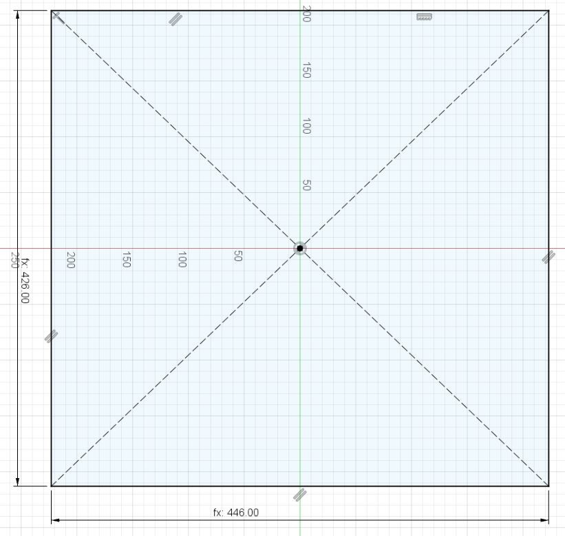
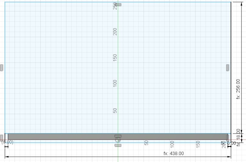
I started by creating a center rectangle sketch and extruded it to WoodThickness.
Step 2
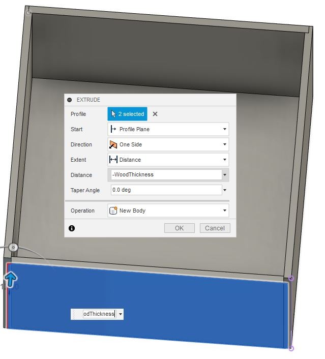
I created two rectangle sketches on the depth side of the bottom part. Another from the top plane of the bottom part to height + WoodThickness + 2xFeltThickness x depth + 2xWoodThickness + 2xFeltThickness with 6mm distance (WoodThickness/2) to the sides of the bottom part. Another rectangle was created with same width and WoodThickness + 6mm height.
I extruded both rectangles to 6mm thickness to both directions from the sketch plane.
Step 3
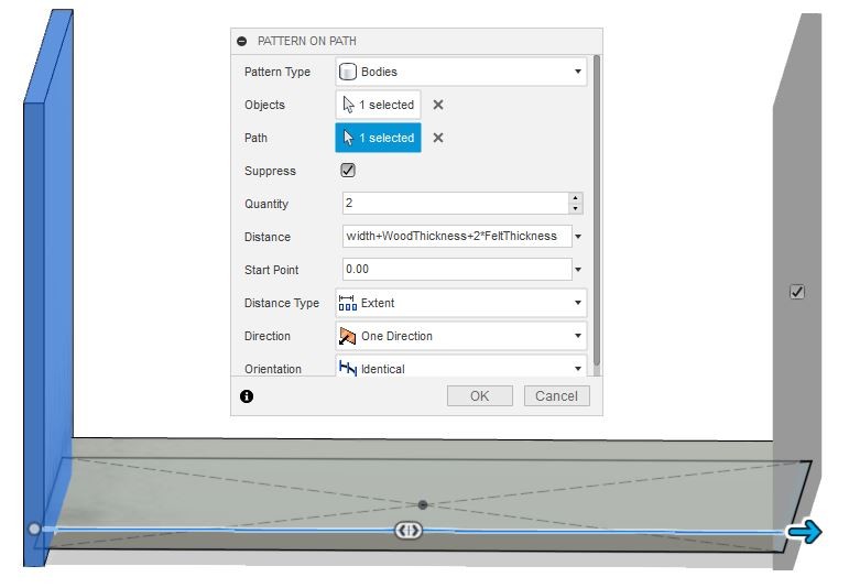
I created a pattern on path with distance width + WoodThickness + 2xFeltThickness to create a equal part to the opposite side.
Step 4
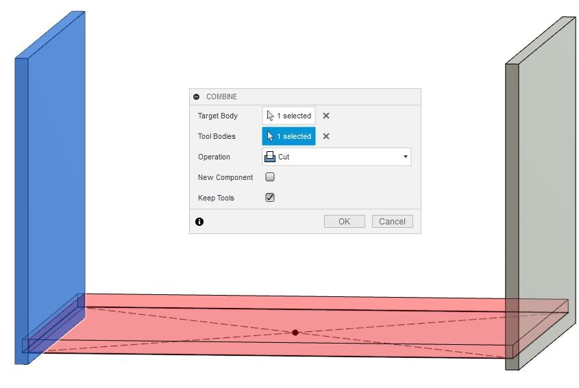
I used combine tool to make slots for the bottom part.
Step 5
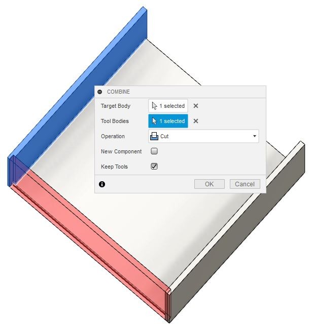
To make a back part of the box I created another sketch with two rectangles on the side plane of the walls that I had just created.
I extruded both rectangles to WoodThickness and used combine tool to make a slot for the bottom part.
Step 6
I created a rectangle to the front side with WoodThickness + FeltThickness + 2 mm gap to top plane of the box to make a room for the lid to move with felt attached to the bottom plane of the lid. I extruded it to WoodThickness.
Combine tool was used again to make a slot for the bottom part.
Step 7
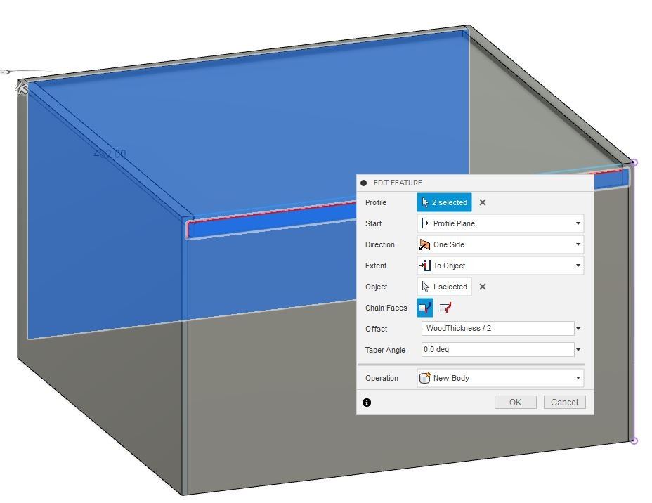
Again, I created two rectangle sketches to the same plane as in the previous step to make a lid for the box. I extruded them to object (inner back wall) with offset -WoodThickness/2.
Step 8
I made an ellipse sketch on the top plane of the lid and extruded it to -WoodThickness/2 to make it easier to pull the lid out.
Step 9
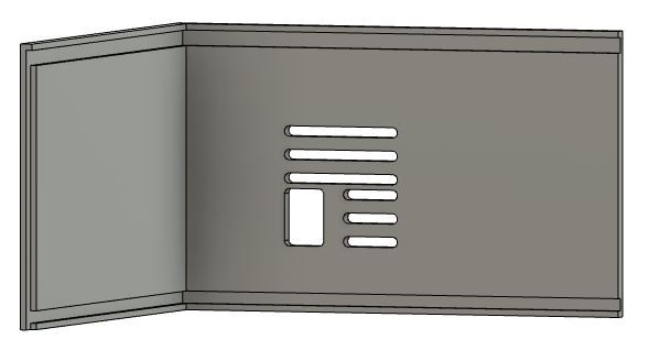
I created holes to the back side of the box for cord and vent and to the front side for pressure hoses.
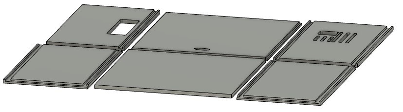
Step 10
Using move and align tools (MODIFY >> Move/Copy, MODIFY >> Align) I arranged all parts to the same plane to make it possible to mill them.
Toolpath generation
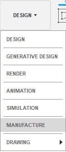
Step 1
I started toolpath generation by changing workspace to manufacture.
I chose MILLING >> SETUP >> New Setup. My coordinate axis are set by default so that z axis points up, x axis points right and y axis points away from a viewer. Hence I chose Work Coordinate System’s Orientation to be Model orientation and Origin to be Model box point. I clicked bottom left corner’s topmost point to set the origin there. For the Model I chose all six bodies.
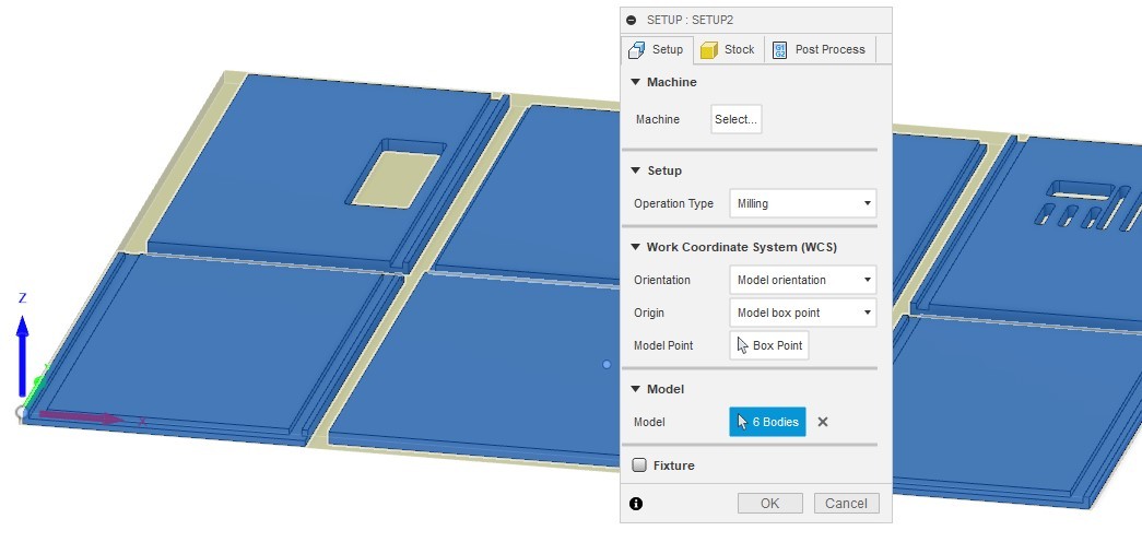
In the Stock tab I changed Stock Side Offset to 3mm. I hit OK to create the setup.
Step 2
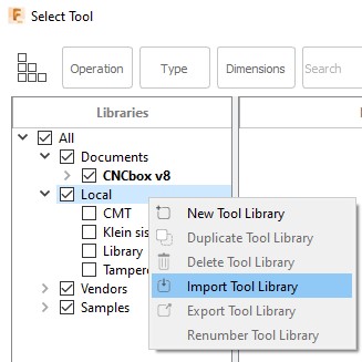
I chose 2D >> 2D Pocket to make toolpaths for cord, vent and hoses holes. In the tool tab I selected the tool I wanted to use. I clicked Tool Select, right clicked on Local, chose Import Tool Library and imported Tampere Fablab’s tool library from my computer.
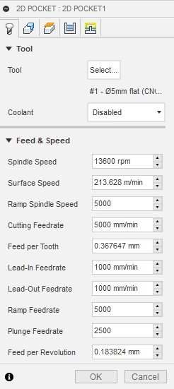
I chose flat tool with 5mm diameter.
Settings for feed and speed:
Step 3
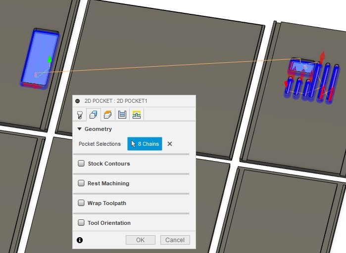
In geometry tab I chose bottom edges of the holes for Pocket Selections.
Step 4
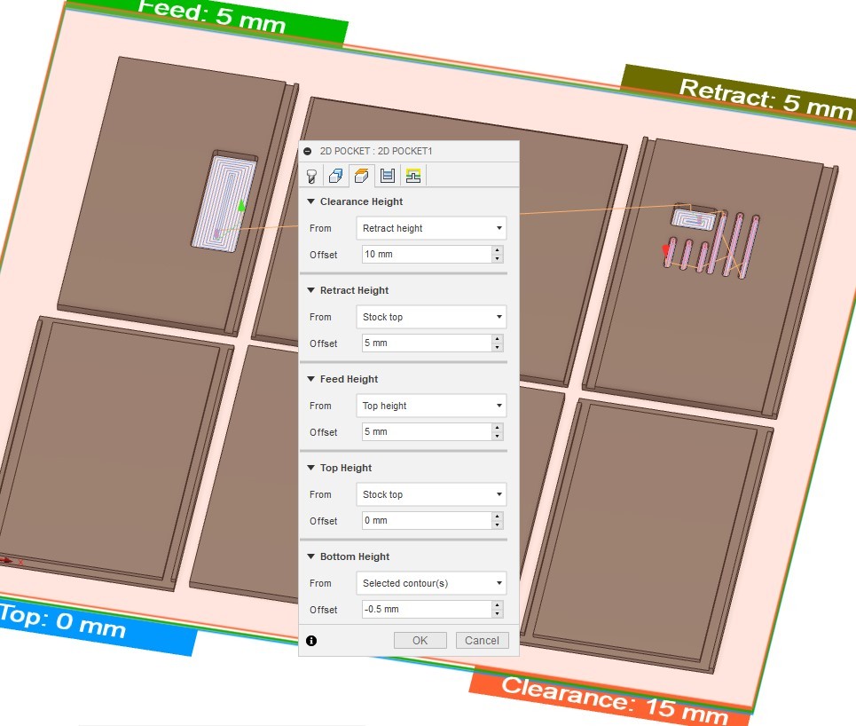
In heights tab I used following settings:
Step 5
In passes tab I made following changes:
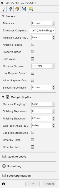
Step 6
In the linking tab I used following settings:
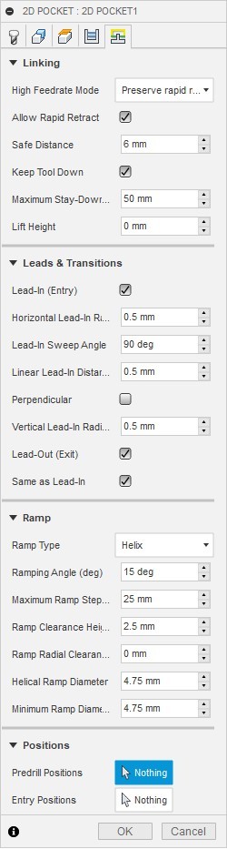
I hit OK to finalize the first pocket settings.
Step 7
By clicking ctrl+D I copied the previous pocket settings. Now in the pocket selection I chose all the assembling slots.
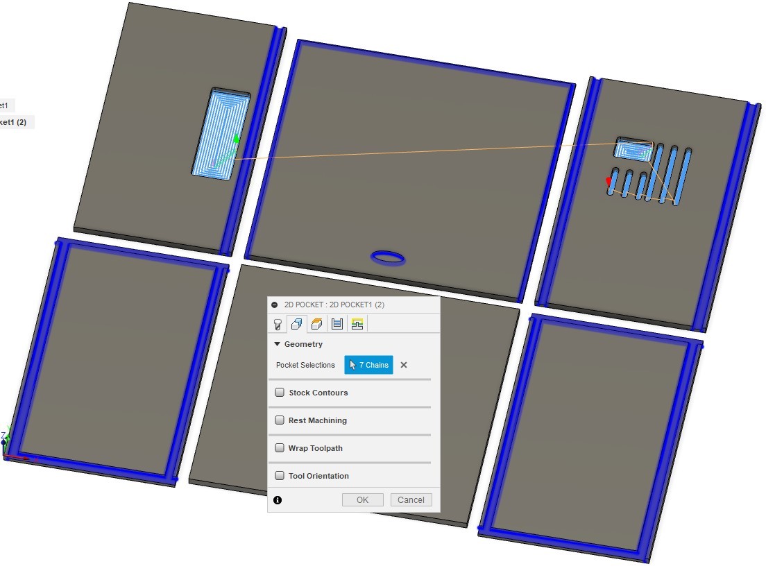
Only modification that I made for the previous settings was in the heights tab where I set bottom height offset back to 0mm. I hit OK to finalize the second pocket settings.
Step 8
Next I created toolpaths for outer edges. I chose 2D >> 2D Countour. The tool was same as in the previous settings. In the geometry tab contour selection I chose bottom outer edges. I chose to have tabs with tap height of 2.5mm and tap distance of 100mm.
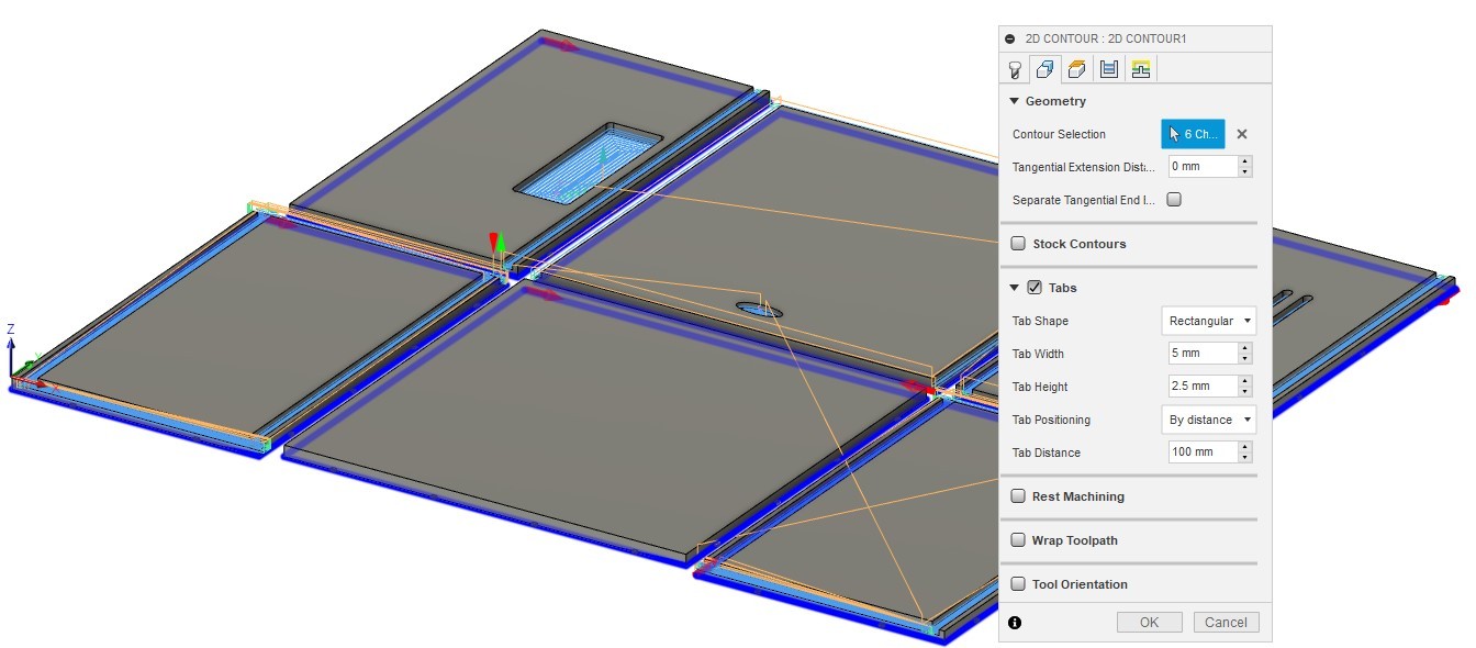
I also changed heights tab where I set bottom height offset to -0.5mm as in the first pocket. I used simulate tool (ACTIONS >> Simulate) to check that all toolpaths looked fine.
Step 9
Next I created a Post Process by right clicking on the setup that I had made.
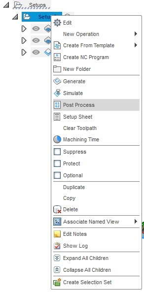
I had added our Fablab’s postprocessor files to Fusions post processor folder so I clicked on Configuration Folder Setup >> Open folder and chose Tampere Fablab Excitech E2-1325.
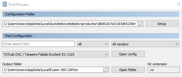
I clicked Post to make the gcode file and saved the file to my computer.
I asked our Fablab Tampere’s laboratory personnel which settings I should use for milling. The setting used here are the based on the recommendation I got from them.
Milling
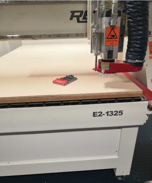
Step 1
Our router in Fab Lab Tampere is Excitech CNC router.
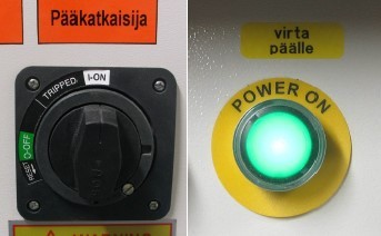
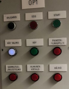
First I switched on router’s electronics and computer. I turned the black main switch in front of the machine cabinet to “ON” position, pressed the green “POWER ON” button in the front panel and log in to computer.
Step 2
Next step was starting the NcStudio software and initializing the machine coordinates system by selecting “All Axes” in the appearing window. This automatic initialization process determines the origin of the machine coordinates.
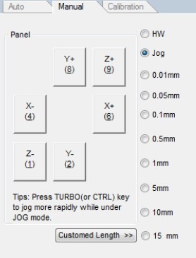
On the right hand panel (in “Manual” tab) are buttons for controlling the router movement. I made sure the movement type radio button was in “Jog” position
Step 3
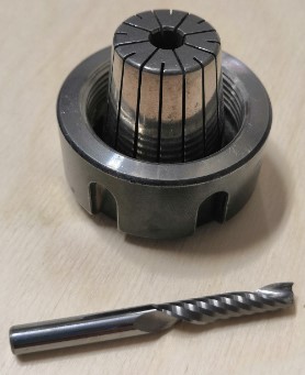
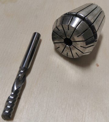
I changed router bit to 5mm flat end tool by inserting the new router bit in the spring collet and tightening the collet nut to correct tightness.
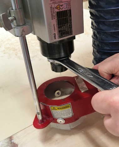
Once the tool was set correctly I lifted the dust removal cover back to to it’s place.
Step 4
Next step was mounting the work piece by using a sacrificial MDF board mounted on the router table T-slots and screwing my 12 mm plywood work piece to the MDF with wood screws.
Step 5
Next step was opening the G-code. In NcStudio, I clicked File >> Unload to remove old nc-file and then clicked File >> Open and load and selected my nc-file and clicked Open.
Step 6
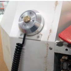
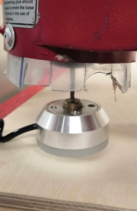
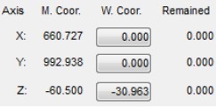
Next step was resetting the Z position of the working coordinates origin. I lowered the Z axis so that the tip of the router bit was about 10 cm above the work piece top surface. I clicked Click Operations >> Mobile calibrator and then clicked Countinue in the confirmation window. After this I grabbed the mobile calibrator from its holder and positioned it under the router bit.
Step 7
Next I selected the XY position of the working coordinates origin by moving the router near the bottom left corner (the origin of my routing trajectory).
I reset the X and Y working coordinates by clicking the corresponding buttons near the top left corner and confirm the resetting by clicking “Ok” in the pop-up window.
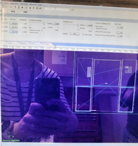
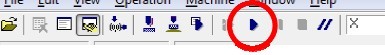
I clicked Simulate button at the top of the screen which draws the routing trajectory as it would be carved in the work piece. Simulation on computer interface:
Important thing at this point was to pay extreme care to the mounting points (screws) and make sure that the router bit, the collet nut or the dust cover will never hit those when following the trajectory.
Step 8
Next step was machining the work piece. I started the dust collector by pressing the green start button.
I put safety glasses and hearing protectors on and pressed Start button.
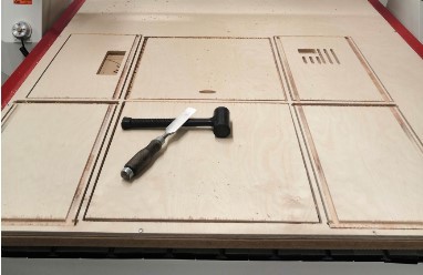
The router started moving along the trajectory shown by the simulation. After about half an hour the routing operation was completed. I cut tabs that held parts on the work piece using a chisel.
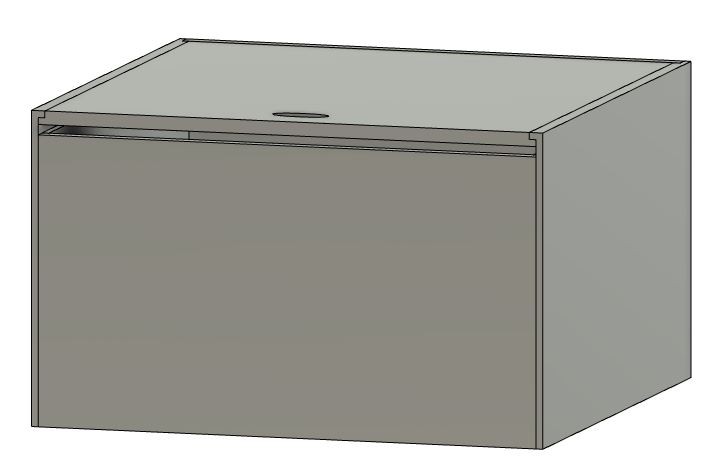
Assembly
I sanded all the edges of the parts and glued parts together using wood glue. They fit just perfectly together so assembly was an easy process. End result is pretty much just what I ecpected to have! The machine fits to box perfectly. Only thing yet to do is to buy the sound insulator felt and install it inside the box.
Reflection
I had at first some troubles to figure out how to make the joints but I used some time in internet trying to find out how people are making boxes with CNC machine. I ended up with this solution since it seemed easiest for me to model. I had to really think through all parameters I used since I had to take plywood and felt thickness into account in the model. I made a sketch on the paper on tried to clarify the dimensions to myself that way. It seemed to work.
The toolpath operation was pretty simple in this project since I was able to use just one tool and 2D operations.
I learned a lot about designing objects for CNC machine and how to run the machine. It is still quite scary process to use the router and I’m not confident enough with my skills to be able to use the machine alone. Maybe one day.