9. Embedded programming
Group assignment
Compare the performance and development workflows for other architectures
Individual assignment
Read a microcontroller data sheet.
Program your board to do something, with as many different programming languages and programming environments as possible.
Group assignment
We worked together with whole Oulu Academy group.
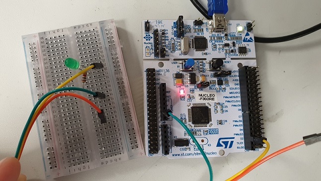
We tested STM32 Nucleo-64 development board with STM32F401RE MCU and ESP32 board using Arduino IDE.
We tested the STM32 Nucleo-64 development board with STM32F401RE MCU and ESP32 LOLIN32 development board using Arduino IDE. ST32 is a family of 32-bit microcontroller integrated circuits by STMicroelectronics. This group is related to same 32 bit ARM processor. The STM32 F4-series is the first group of STM32 microcontrollers based on the ARM Cortex-M4F core. The F4-series is also the first STM32 series to have DSP and floating point instructions. The F4 is pin-to-pin compatible with the STM32 F2-series and adds higher clock speed, 64 KB CCM static RAM, full duplex, improved real-time clock, and faster ADCs. All devices offer one 12-bit ADC, a low-power RTC, six general-purpose 16-bit timers including one PWM timer for motor control, two general-purpose 32-bit timers. They also feature standard and advanced communication interfaces.
- Up to three I2Cs
- Up to four SPIs
- Two full duplex I2Ss. To achieve audio class accuracy, the I2S peripherals can be clocked via a dedicated internal audio PLL or via an external clock to allow synchronization.
- Three USARTs
- SDIO interface
- USB 2.0 OTG full speed interface
See the data sheet STM32F401x for more information.
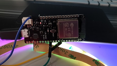
ESP32 is a series of low-cost, low-power system on a chip microcontrollers with integrated Wi-Fi and dual-mode Bluetooth. The ESP32 series employs a Tensilica Xtensa LX6 microprocessor in both dual-core and single-core variations and includes in-built antenna switches, RF balun, power amplifier, low-noise receive amplifier, filters, and power-management modules. ESP32 is created and developed by Espressif Systems, a Shanghai-based Chinese company, and is manufactured by TSMC using their 40 nm process. See the more details about ESP32 LOLIN32 in the link.
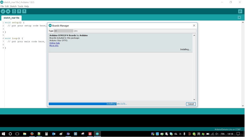
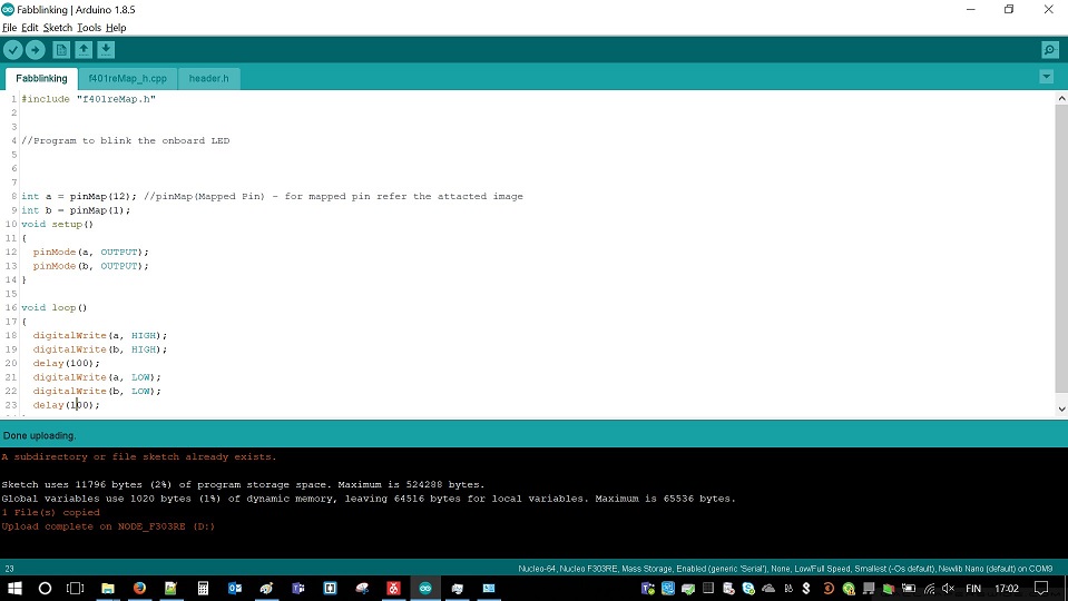
We installed Board Manager for the Nucleo board
Then we defined the board information (Board and Board number) in Tools
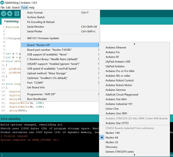
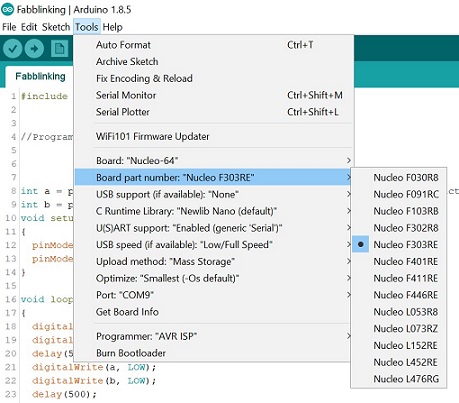
and run the blinking test code for the board

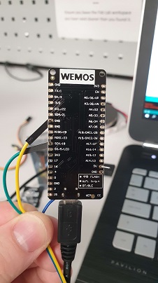
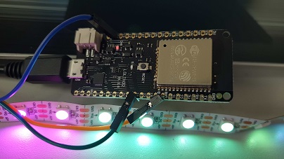
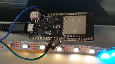
With very similar steps and using ESP32 we were able to make some LEDs fading. We just had to taking into account pin numbers, find proper and connect them with LED stripes.
Individual assignment
Read ATTiny datasheet
ATTiny datasheet has 238 pages. I scanned it briefly to understand what it contains, so that I can come back to it when needed. I read more detailed the short version of the datasheet (22 pages) that gives a quick reference on the microprosessor features, lists Registers and Commands.
ATtiny24A/44A/84A is a low-power CMOS 8-bit microcontroller based on the AVR enhanced RISC architecture. By executing powerful in structions in a single clock cycle, the ATtiny24A/44A/84A achieves throughputs up to 1 MIPS per MHz allowing the system designer to optimize power consumption versus processing speed.
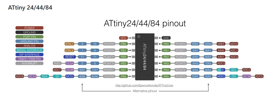
Figure 1-1. shows the Pinout of ATtiny24A/44A/84A and Block Diagram (Figure 2-1.) gives an overview of the architechture. More detailed Pin descriptions are in chapter 1.1
Resources like drivers, application notes, data sheets and descriptions on development tools are available for download at http://www.atmel.com/avr.
The documentation contains simple code examples that briefly show how to use various parts of the device. Examples are written in c-code.
Programming my board
First I installed Arduino 1.8.8.
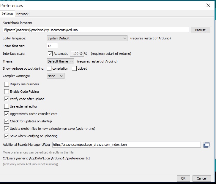
Then I copied Boards Manager installation url from GitHub SpeceKonde. I opened Arduino File/Preferences and pasted the url in Additional Boards Manager URLs.
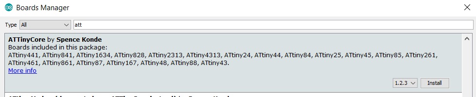
Then I opened Boards Manager and installed ATTinyCore by SpenceKonde.
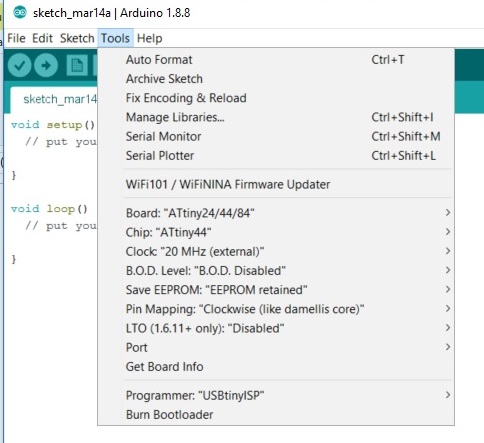
Next I opened Tools and defined Board and Chip to ATTiny44, Clock to 20mHz and Programmer as USBTinyISP.
Then I did Burn Bootloader. When using a chip for the first time, or after changing the clock speed or BOD settings, you must do “burn bootloader” to set the fuses.
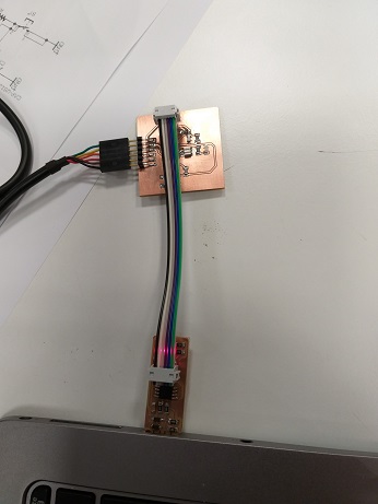
I attached my board to my laptop with FTDI cable to provide the power. Then I inserted my USB programmer to my laptop and connected the ISP cable between the programmer and the board.
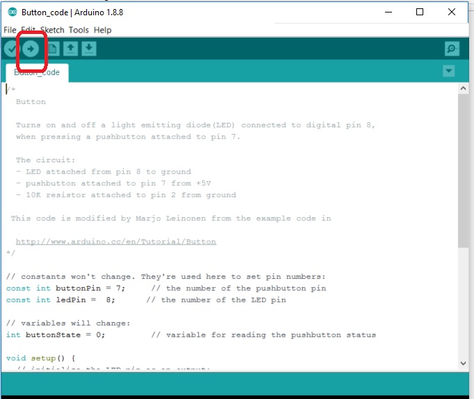
I opened Button code in File / Examples / Digital. I set the pin numbers according to my board pins, I have PA7 and PB2 as my button and led ports in ATTiny44A.
const int buttonPin = 7; // the number of the pushbutton pin
const int ledPin = 8; // the number of the LED pin
I checked the correct pin numbers from ATTiny Pinout map
and ran the code by pushing arrow.
I got an error message, that USBtiny was not found. What could be the problem?

I checked all the settings again and saw that all the changes I made to ATTiny in Tools were lost. I did the changes again (Board and Chip to ATTiny44, Clock to 20mHz and Programmer as USBTinyISP).
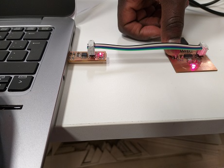
I saved and ran the code again. Now led was turned on. Led will be off when pushing the button.

In the code, if the buttonState is HIGH, LED is turned on, else LED is turned off.
if (buttonState == HIGH) {
// turn LED on:
digitalWrite(ledPin, HIGH);
} else {
// turn LED off:
digitalWrite(ledPin, LOW);
I modified the code so that if buttonState is HIGH, LED is turned off.
if (buttonState == HIGH) {
// turn LED off:
digitalWrite(ledPin, LOW);
} else {
// turn LED on:
digitalWrite(ledPin, HIGH);
Now the led is on only when the button is pushed.
I also tried the Arduino examples for LED blinking and LED fading. I modified the example codes to have correct pin numbers and I also changed the blinking interval and the fade amount to see how the changes are affecting. Everything was working as expected.
Reflections
Embedded programming is completely new to me and I have learned a lot during this week. Luckily the Arduino example codes are very simple, so it is easy to understand what is the program doing and what needs to be changed in the code when working with different microcontroller (ATTiny44).
There are several phases in the programming of the board and every detail and setting needs to be correct to make programming successful. Data sheet is needed, especially the pin descriptions for this assignment. I am sure that in further assignments I will get more deep with the programming and data sheets, it is needed for my final project. Looking forward to that :).