4. Computer controlled cutting
This week we learned laser-cutting and vinyl cutting. Work contains Group work and individual work.
Safety instructions from Epilog Laser Fusion user manual.
Please read the following warnings and recommendations and follow them closely at all times!
NEVER let the laser system operate if it will be unattended.
KEEP the area around the machine clean and free of unnecessary clutter, combustible materials, explosives, or volatile solvents such as acetone, alcohol, or gasoline.
ALWAYS keep a properly maintained and inspected fire extinguisher on hand.
ALWAYS use air assist when vector cutting.
BE CAREFUL! When vector cutting. Many materials have the potential to burst suddenly into flames – even materials that may be very familiar to the user. Always monitor the machine when it is operating.
KEEP YOUR LASER SYSTEM CLEAN – A build up of cutting and engraving reside and debris is dangerous and can create a fire hazard in its own right. Keep your laser system clean and free of debris. Regularly remove the vector grid to clean any small pieces that have fallen through the grid.
Using Epilog Laser Fusion
Cutting modes:
Raster Mode – This mode will only engrave. Vector lines will not be processed from this mode.
Vector Mode – This mode will only vector. Raster images will not be processed from this mode.
Combined Mode – By properly setting up your artwork you can both engrave and cut from this mode.
Work flow:
- Turn ON the laser cutter
- Make sure that AIR VENTILATION is ON.
- Check where the emergency stop -button of the machine is located.
Place the material in cutter and use following fuctions to get the cutting started:
JOG - Choose the spot to be used as an origin/ from where to start cutting. Push the red laser -button on the UI in order to see a visible laser light above the material showing the current origin. By pushing the joystick, find the origin by moving the laser head to the correct place being the upper left corner of the cutting file, and press the joystick to reset the XY -values and set the origin to be at that place.
FOCUS - Set the correct distance between the laser and the material. Adjust the distance by using the triangle shaped manual focus gauge placed on the laser head. By pushing the joystick, move the material bed up and down so, that the focus gauge will just touch the surface of the material. Remember to remove the focus gauge from the laser head after setting the focus.
JOB - Select your job from the printing queue (the job is sent from the control PC and you have to do this before starting the cutting). When the job is selected, the display will show an estimated cutting time of the job.
Now press ‘GO’ and the laser cutter will start cutting.
Group work
Our group: Lukasz, Gleb, Perttu and I.
File format we used for laser cutting is PDF. For the cutting the thickness of the lines must be 0.02mm (0.001”). Thicker lines will not be cut in Vector mode.
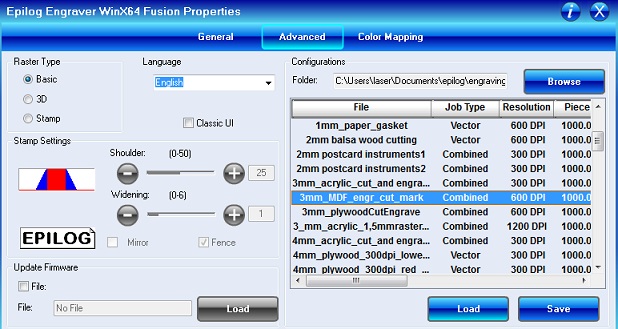
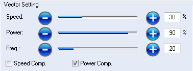
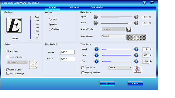
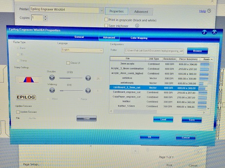
To put your drawing into cutting you need to open the PDF file on the control PC and press Print and open Settings. From the General page you can choose Raster (for engraving), Vector (for cutting) or Combined (for both) mode. Choose the Resolution as in your original image for better result. Set the Raster and Vector setting according the material.
Comparing Speed and Power
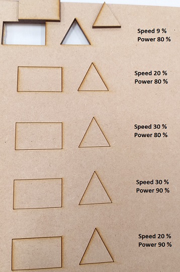
We had a simple design created with Inkscape and saved as pdf for the cutting, 0,02 mm line width. We used 3 mm MDF.

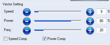
First cut was done using the pre-defined values for 3 mm MDF; Speed 9 % and Power 80 %.
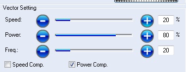
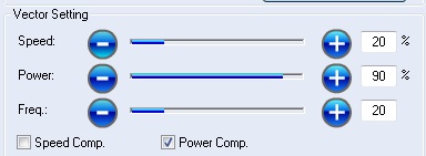
Cut 2 was done with Speed 20 % and Power 80 %.
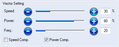
Cut 3 was done with Speed 30 % and Power 80 %.
Cut 4 was done with Speed 30 % and Power 90 %.
Cut 5 was done with Speed 20 % and Power 90 %.
Result was that only the Cut 1 was cut through, the others not. So the Speed is real important value to choose correctly. Too much speed cannot be compensated with little more power.
Measuring kerf:
Kerf is defined as the width of material that is removed by a cutting process. Kerf ranges from 0.08mm – 1mm depending on the material type and thickness.
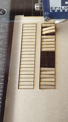
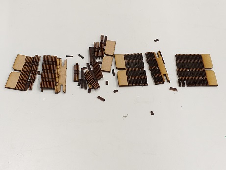
First we drew with Inkscape a rectangular and divided it with lines in 20 pieces.

Next we laser-cut it using different settings in speed. First we cut with pre-defined values for 3 mm MDF. After that we added some speed.
We noticed that having too fast speed, the material did not cut through and when we cut it again, the pieces fell down. This was not a good way to do it.
Then we measured the pieces (20 pcs) and calculated the kerf. We did the measurement many times because the meter was not accurate.
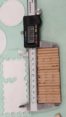
Epilog Laser Fusion, 3 mm MDF: Design length 10 cm - Cut length 9,82 cm diveded with 20 -> kerf is 0,09 mm
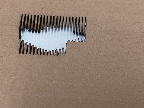
We did the same process with acrylic
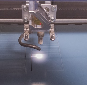
Epilog Lase Mini, 3 mm acrylic: Design length 10 cm - Cut length 9,53 cm diveded with 20 -> kerf is 0,23 mm
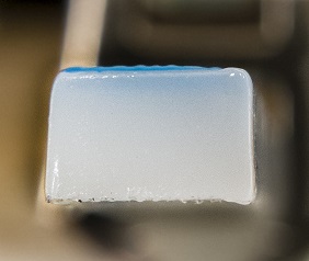
So the kerf depends a lot about the material. Following picture shows how the acrylic is melting.
Individual work
Vinyl cutting
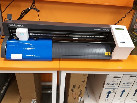
I used Roland GS24 vinyl-cutter.
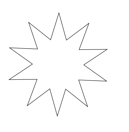
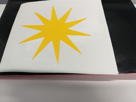
I drew a simple star with Inkscape. Here the line width is not important, I had 1 mm.
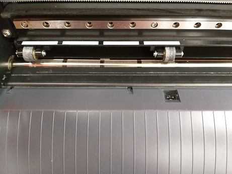
First I set the vinyl sheet to the vinyl cutter. I lowered the loading lever, then aligned the pinch rollers with the grit marks and then raised the loading lever.
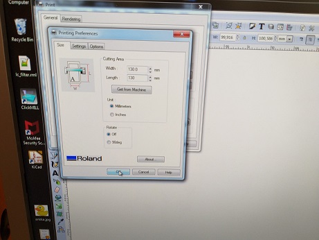
Then I set the correct printing equipment and Printing Preferences. I changed the values to be 130 mm x 130 mm, to be a little bit bigger than my star. You can also press “Get from machine”.
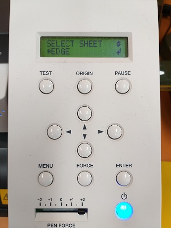
Then I pushed Menu button in cutter and selected the correct sheet. When using Edge -option, the machine measures and detects automatically the edges of the vinyl.
And I pushed “Print”.
Finally the sticker is done. This sticker is a simple shaped, so the weeding is not problem. “Weeding” the cut vinyl is the process of removing the unwanted areas from the final cut design. For more complex shaped stickers you may want to use a knife or tweezers to remove the unwanted parts of vinyl. For many small parts or complex parts transfer tape can be used to ease the work.
Sounds simple! And maybe this works if everything is carefully checked! I made many mistakes :)
Here are the main problems I faced:
- cutting area width and length was not defined according to the document size in the Inkscape file - > nothing was cut. First I was not sure what was the problem so I changed the small vinyl sheet to the roll.
- the picture was located in the upper left corner of the Inkscape document -> the cut was created to incorrect place in the sheet (that was already cut area) -> I moved the picture to the lower left corner
- I did not check that the Inkscape document was really empty when drawing the star -> everything (even if it was not visible) was cut and it became a mess
- pin roll was in the incorrect place and it limited the cutting area -> only half of the star was cut -> make sure that pin roll is set correctly
Press-fit kit
I used Fusion 360 for the design, a square with press-fit slots.
I started the work by creating parameters with Modify/Change Parametes -tool.

The parameters I used are:
SquareSize: 50 mm
Thickness: 3 mm (this is the thickness of the material I am using)
Kerf: 0,09 mm (this is measured in the group work and I am using the same material)
SlotDepth: 10 mm * 2 (I used Center Rectangular for the slots, the actual depth will be 10 mm)
Chamfer: 3 mm (I am using Chamfer-tool for slot chamfers)
SlotWidth: Thickness - Kerf
First I draw a 50 mm * 50 mm square and slots using Center Rectangular with the parameters mentioned above.

Next I extruded the sketch with Thickness-parameter (3 mm) for Distance. I also made the chamfers with Chamfer-tool, using Chamfer-parameter (3 mm).

Now the shape is done.

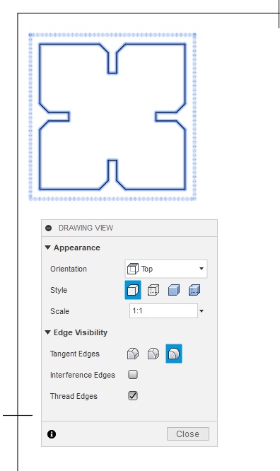
Next I need to produce a 2D file, that can be printed with laser-cutter. I am doing it using Model/Drawing/From Design -tool.
In the DRAWING VIEW -box I changed the orientation to Top, Style to Visible Edges and left Scale to 1:1 and click ok. I Duplicated the object a few times by selecting DRAWING VIEWS/Base Drawing and repeated the process described earlier.

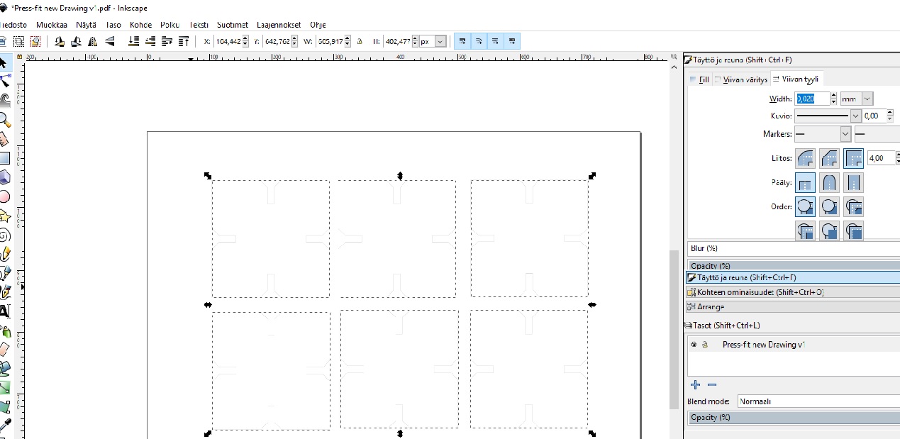
I saved the file as pdf and opened it in Inkscape to adjust the line width to 0,02 mm.

Now the file is ready for the laser cutter.
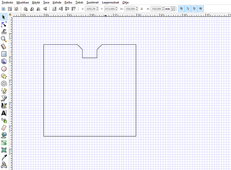
I started the work by designing one part using the instructions in Fabacademy Tutorials. I used Inkscape for the design.
First I drew a square. Then I drew a smaller square partly on the top of bigger square and used command Path/Difference:
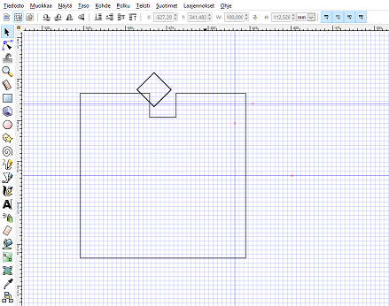
Next I drew another square and rotated it 45 degrees and placed it partly on the top of a slot corner and used again Path/Difference -command to create a chamfer.
I used Nodes-tool to separate the slot side of the square and cloned it to create a square with a slot + chamfer on each side. The difference between copying and cloning is that with cloning all pieces will be changed when modifying the original part. Now I can easily modify the original slot size according the used material and the change will be affective to all slots at the same time.
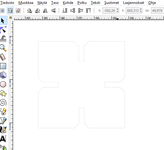
Now I have the basic shape done. I created a copy of that and modified it to longer rectangular with a living hinge. I want to test how this works with construction kit. The hinge pattern I drew using several ellipses. I defined the line width to be 0,02 mm for all pieces.
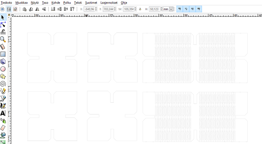
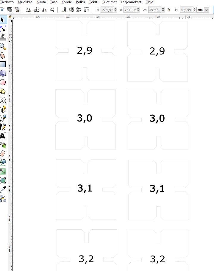
I also created test pieces with different slot sizes
I started the laser-cutting with cardboard and test pieces, I used Epilog Laser Mini-laser cutter. First I saved the file as pdf and made correct settings for the printing. I chose the pre-defined settings for cardboard and they seemed to work fine.
I set the starting point for the cutter and pressed start.
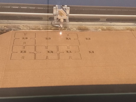
Test pieces with 2,9 mm and 3,0 mm slots worked well with cardboard, 3,1 and 3,2 mm slots were too loose.
Next did the same trial with MFD, I used Epilog Laser Fusion-laser cutter. I loaded the pre-defined values for 3mm MDF for Speed, Power and Freq. from Properties/Advanced. 2,9mm slots work well with 3 mm MFD. This is in line with the measured kerf, that was 0,09 mm.
The final pieces I cut from 3 mm MFD with 2,9 mm slots.
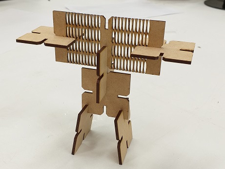
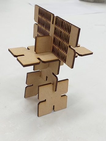
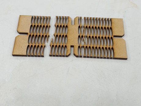
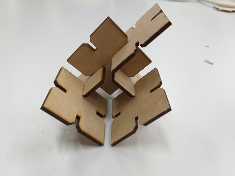
Here is my press-fit construction kit made of 3mm MDF:
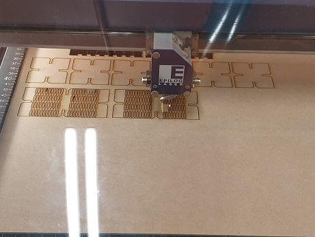
Here are some pictures of my living hinge trial with cardboard and MDF.
First cardboard. There was too much power for this material. Cardboard started burning (just a little bit) and I had to stop cutting. Remember always to watch your cutting!
Living hinge trial with 3mm MDF. Pattern had too many lines too close each others.
Another living hinge trial with 3mm MDF and different pattern. This did not work either. I need to study more how to design a working living hinge. I have used an extension file having ready made living hinge patterns, but I am interested in creating my own design.
After all this work I heared that it is not acceptable to do this assignment design with Inkscape, so I started to do a new and real parametric design using Fusion 360.
I started the work by creating parameters with Modify/Change Parametes -tool.
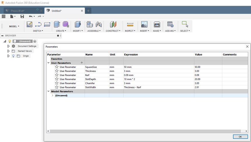
The parameters I used are:
SquareSize: 50 mm
Thickness: 3 mm (this is the thickness of the material I am using)
Kerf: 0,09 mm (this is measured in the group work and I am using the same material)
SlotDepth: 10 mm * 2 (I used Center Rectangular for the slots, the actual slot depth will be 10 mm)
Chamfer: 3 mm (I am using Chamfer-tool for slot chamfers)
SlotWidth: Thickness - Kerf
First I draw a 50 mm * 50 mm square and slots using Center Rectangular with the parameters mentioned above.
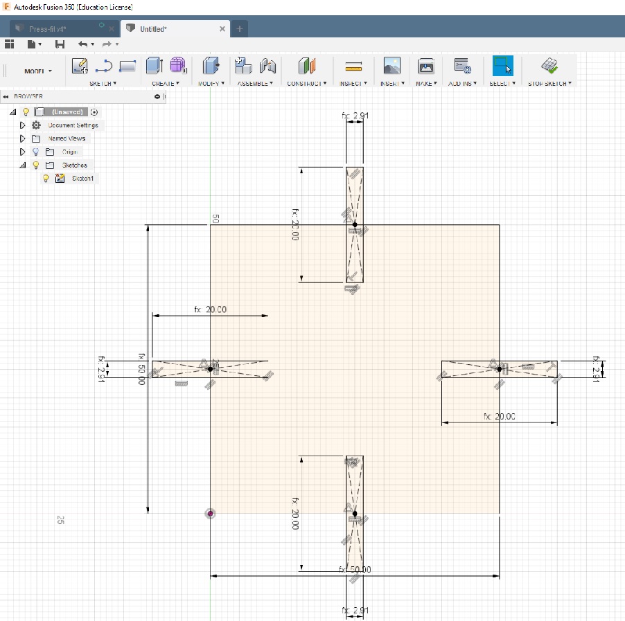
Next I extruded the sketch with Thickness-parameter (3 mm) for Distance. I also made the chamfers with Chamfer-tool, using Chamfer-parameter (3 mm).
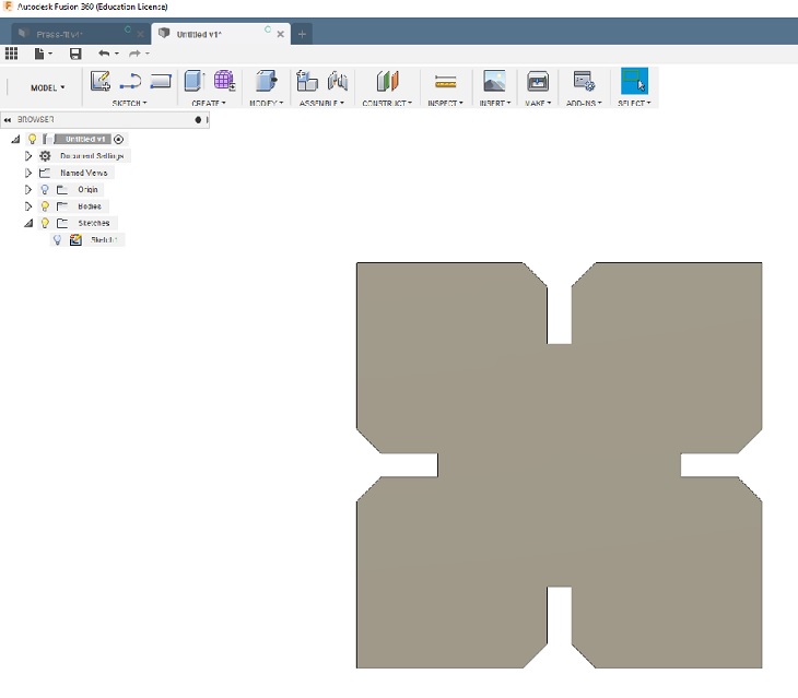
Now the shape is done.
Next I need to produce a 2D file, that can be printed with laser-cutter. I am doing it using Model/Drawing/From Design -tool.
In the DRAWING VIEW -box I changed the orientation to Top, Style to Visible Edges and left Scale to 1:1 and clicked ok. I created copies by selecting DRAWING VIEWS/Base Drawing and repeated the process described earlier.
I saved the file as pdf and opened it in Inkscape to adjust the line width to 0,02 mm.
Now the file is ready for the laser cutter. I opened the pdf file in laser-cutter PC and printed it. I used 3 mm MDF and I loaded the pre-defined values for 3mm MDF for Speed, Power and Freq. from Properties/Advanced.
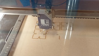
And here is my kit
Reflection
I have learned the nature of laser cutting; what kind of materials can be used, how the kerf is measured and how to do parametric design. It is very easy with Fusion 360, but i had to study how to produce 2D files that are needed for laser cutting.
I have also learned how the documentation should be done. I had to re-do some parts of this weeks assignment, because I had not saved all detailes I needed for the documentation.
I was a bit confused when I realised that the Fabacademy Tuorial for Inkscape Press-fit kit was not ok to use for the assignment. For me it was not clear what was the requirement for the parametric design. But now I have learned it when doing it multiple times.
Biggest frustration has been the group work. We did lot of cutting and measuring, but it seems that the requirements are very unclear and we probably need to do everything again. The evaluation criteria is very unclear and in my opinion this should be defined so that everyone knows what is expected for the result. We have been discussing for four weeks if our work is enough or not.
Files
Press-fit Fusion stl
Press-fit Fusion f3d
Press-fit Fusion Drawing pdf
Press-fit Inkscape svg
Press-fit Inkscape pdf
Vinyl star svg