12. Output devices
Group assignment
Measure the power consumption of an output device
Individual assignment
Add an output device to a microcontroller board you’ve designed, and program it to do something
Group assignment
Members: Lukasz, Gleb, Perttu, Jobin and I
Measure the power consumption of an output device.
Green LED
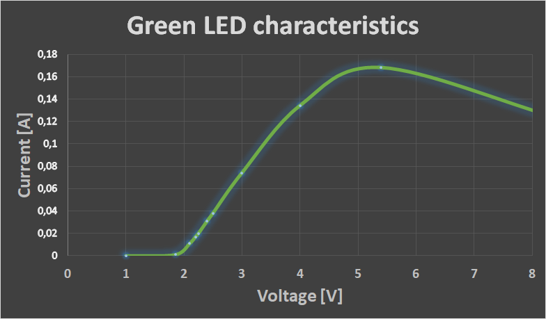
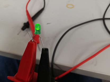
For light emitting diodes the results are visible with bare eye and connection is very simple. We found some random green LED on burned board. Our decision was to measure forward voltage to current characteristics. From this power would be easily calculated as Power = Voltage x Current.
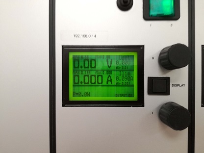
We connected the LED to the laboratory power supply. It is a smart construction as it has both current and voltage limited output. It would be really difficult to burn the LED but we managed to do that.
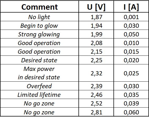
We were feeding LED with voltage, where current was limited every time. We obtained full characteristics from barely glowing to final breath of our LED. Results are shown below.
Our power supply
Our convict - green LED
Observations during measuring process below:
Motherboard Fan
Our next choice was cooling fan.
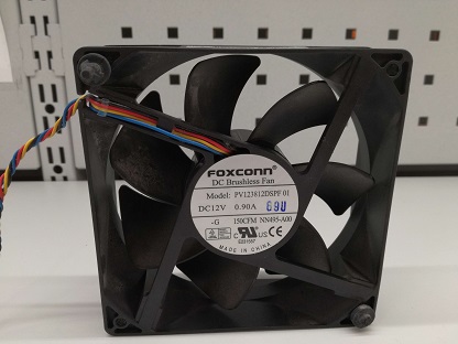
This was doing its best to cool down some electrical circuit. Nominal values were 12 Volts at 0.9 Ampere. Once again we used our laboratory power supply. This time we limited current to maximum value of 0.9 Amp and played with voltage. We obtained both Current vs Voltage and Power vs Voltage characteristics.
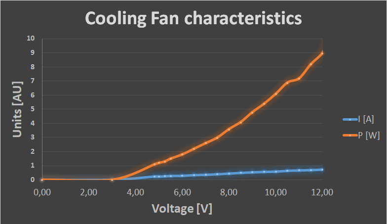
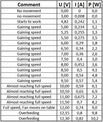
We wrote down our observations during measuring process. Observations below:
Individual assignment
This week I wanted to design a board to control the LED strip in my final project lamp.
I had to think the requirements:
- 12 V input power and jack for that
- pins to attach led strip
- connection to the sensor board (to get the led dimming info)
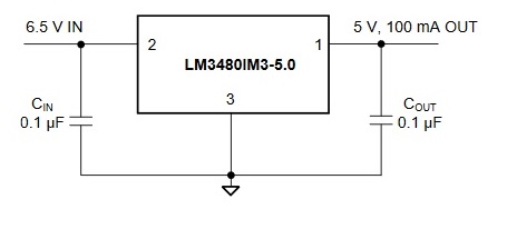
Having 12V input voltage, a regulator is needed to get 5V output for the ATTiny44. I chose lm3480 and checked the recommended circuit design from component data sheet. I need also two capacitors for that.
For the LED strip I need also nMosfet to control the voltage.
I used Eagle to design my LED control board, just like I learned on Electronics design week.
First I designed the schematic
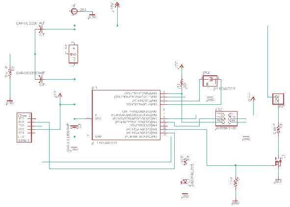
And the board design
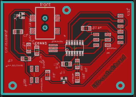
After that I milled the board and soldered the components.
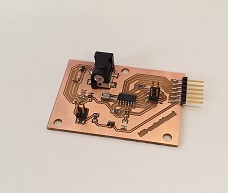
I tested the board with multimeter and everything seemed to be fine. Ready to program the board.
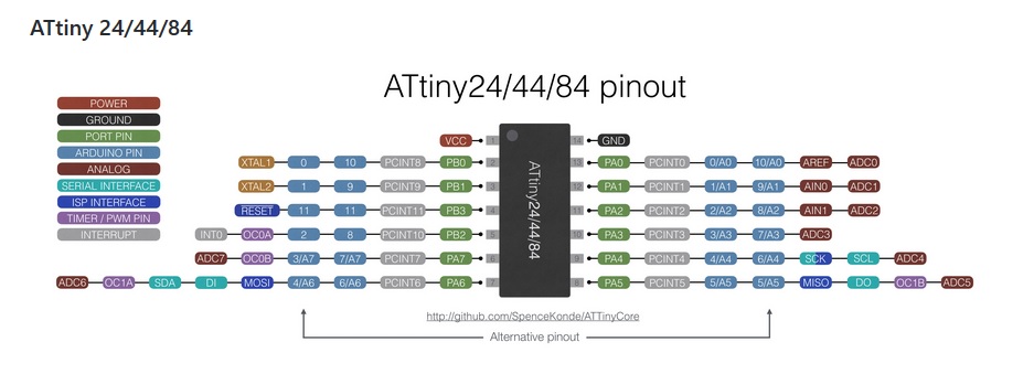
For testing purposes I decided to use simple Arduino code for leds. I used this same code already on week09, so it should work. For my new board I need to modify the pin number in code. In my board and ATTiny44 the used pin is 11, that is pin 2 in Arduino, this can be checked from ATTiny pin map.
I used my programmer to program the board.
Something is wrong, regulator was burned. I found out (too late) that this type of regulator may not be used when 5V power is connected to board from e.g. FTDI connector. And I did connect the FTDI cable when programming the board. This was not ok.
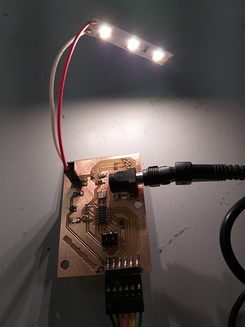
I decided to do the testing of the board without regulator. I connected the board to 12V power to power the led strip. ATTiny will get the power via FTDI cable.
Led strip is working, light goes on and off. But not fading as it is supposed to. The problem here seems to be that the pin I chose to be connected to led strip is wrong type. I used ATTiny pin 11, and I should have used pin numbers 5, 6, 7 or 8. These pins are Timer/PWM pins in ATTiny and the code is designed so that PWM pin has to be used. PWM pin has a timer with output compare functionality. This is why the ATTiny is not able to control the led strip correctly. But at least the led strip has the light.
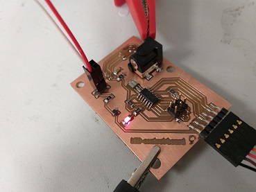
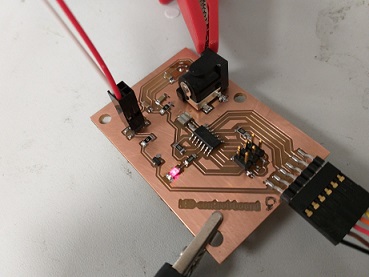
I have also a red led soldered in my board, connected to ATTiny pin number 5. I can test the code with that. I modified the code to use Arduino pin 2 and programmed the board. Now the red led is fading and brightening as it should.
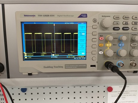
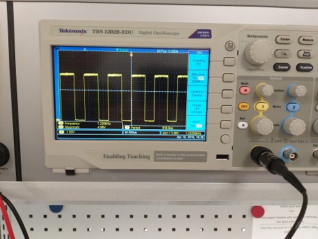
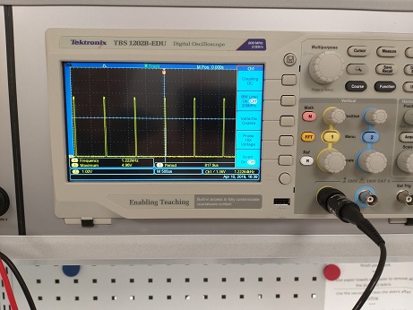
In oscilloscope you can see how the signal is changing along the fading led.
Reflections
When designing a PCB you need to carefully thing what is needed and how the PCB will be used. You actually need to understand the component requirements and their physical sizes and which components require some other additional components. Component data sheets are very valuable in this work, but you also have to learn how to read them. When this assignment was completed I realized that I cannot use this PCB for my final project like I planned. I need to design and make another, better version of it. For example I need to use different ATTiny pins for the led controlling. And I need to connect the jack the other way around. But it is true, that you learn more when everything is not going perfectly in the first round.