8. Computer controlled machining
Group assignment
Test runout, alignment, speeds, feeds, and toolpaths for your machine
Individual project
Make something big on a CNC machine.
Group assignment
This week the group was all Oulu Fab Academy students together. The pictures are taken by Jobin.
Eino showed us the CAM operations needed to prepare nc-file for cutting. He also showed how the machine works and gave the safety instructions. You always need to have safety glasses on when using machine. Also hearing protection is needed.
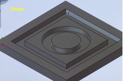
Here is the group work design created with Fusion 360:
We went through following issues:
- Starting (powering on)
- Software
- Resetting axels
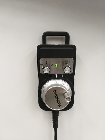
- Moving spindle (X, Y, Z), Computer & Hand wheel
- Changing tool
- Setting and fastening of Stock piece
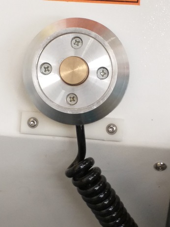
- Setting origo (X, Y, Z), Z with mobile calibrator and manually
- Loading nc code
- Simulating
- Machining final model
We used Fablab CNC machine and NC Studio software.
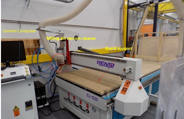
We opened the design file that supports CMC machine (NC file). We connected the flat milling bit of size 8 mm, the feed rate was 80% of the maximum 6000 mm/min to 4800 mm/min. Spindle speed is 80% of the maximum 15000 rpm-12000 rpm. We chose the board for cutting and fixed it on the table with screws. We set the Z origin both manually and automatic to the learn the process. XY position was set to zero avoiding screw region.
Cut piece and measuring.
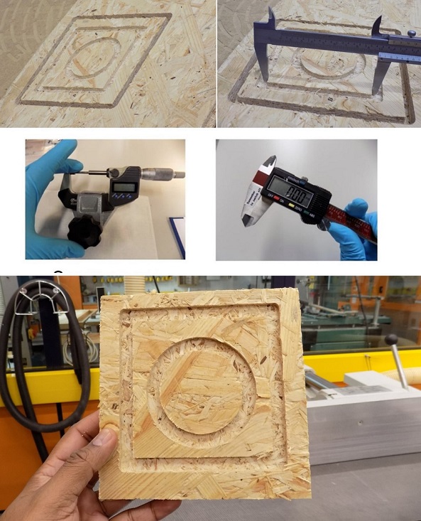
Here are the measurements
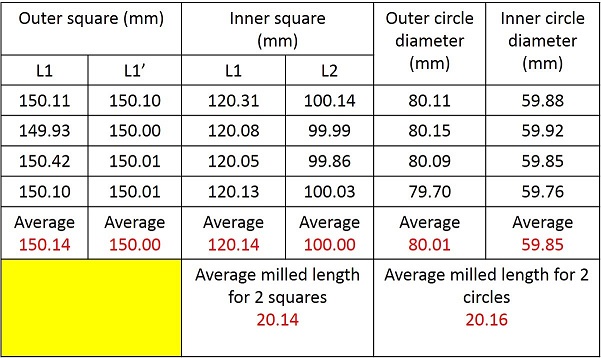
We easured the average milling length for 2 squares is 20.14 mm while the average milling length for the 2 circles is 20.16 mm. Both values are close and error is minimal in comparison with the 3D design file.
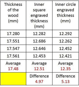
We also documented the engraved area from the square, and circular engrave thickness measured before and after milling using digital screw gauge. See the results and difference in thickness from the square area and the circular area from the below table.
Individual project
Design
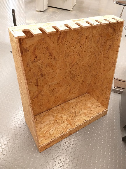
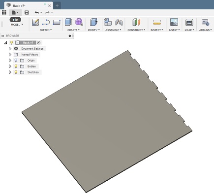
I made a rack (80 cm width, 90 hight, 35 cm depth) for airsoft guns. I used Fusion 360 for the design.
I needed 6 components that are combined with finger joints.
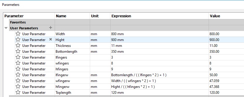
I started with defining parameters for my design
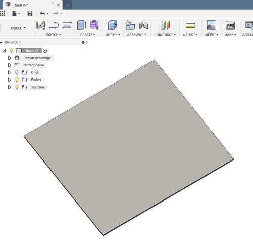
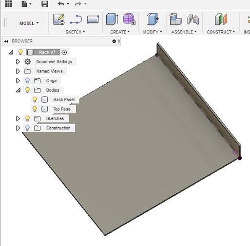
First I drew a square (80 cm * 90 cm) and extruded it to 11 mm (thickness parameter), this is the Back Panel of the rack.
Then I created one finger and used Create Pattern / Rectangular pattern to have fingers for the whole edge.
Next I created Construction Plane to get the Top Panel in 90 degree edge.
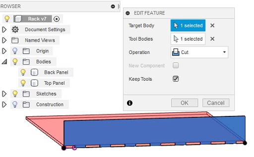
Next I used Modify / Combine tool to cut matching fingers to the Top Panel.
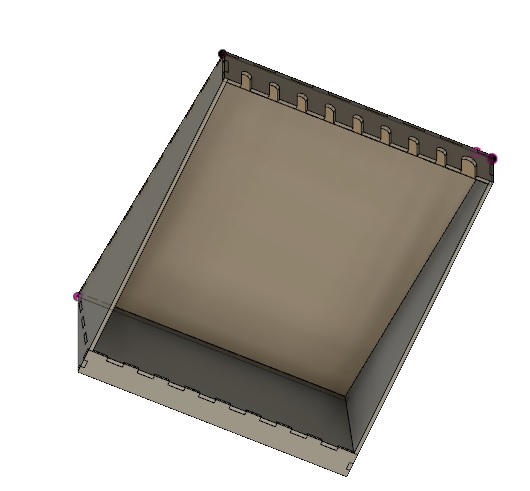
I made the other parts using the same process. Here is the rack design.
When the components were ready, I set them side by side in a new file and started to do the needed operations for the manufacturing.

New Setup:
First I need to set the origo. I set Orientation as “Select X and Y axes”, ticked “Flip X-axis” and set Origin> Model box point. I selected the lower left corner as origin.
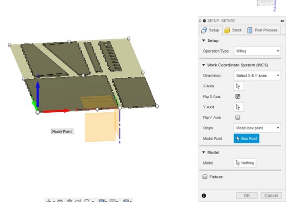
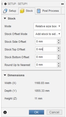
Then I changed stock offsets as 0 mm and clicked OK in Stock section.
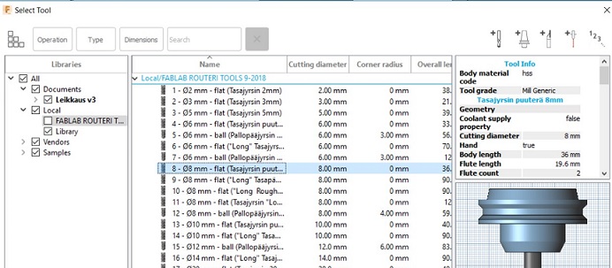
Next I created tool paths for pockets. I chose “2D Pocket” and in Tool section, I chose FabLab tool library I added 8mm flat bit. I had uploaded the Fablab routeri tools -file earlier from Fab Lab Oulu Wiki Space. There is also CAM post processor file for Fusion 360, that is needed later.
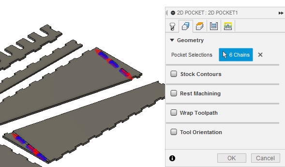
In Geometry section, I chose the pockets I wanted to create
In Passes section I set Multiple Depth to 3 mm as Maximum Roughing Stepdown and ticked Use even stepdowns. I also removed the mark on Stock to leave.
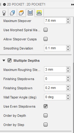
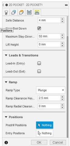
In Linking section I removed the marks on Leads & Transitions. This means that the bit starts milling on the starting point which is defined in the design without any extra cut before or after.
I selected Plunge as Ramp type. It is suitable for milling wood.
Next I made tool paths for cutting. I selected 2D / 2D contour. I used the same tool, 8mm flat. In Geometry section, I selected all the lines which I wanted to cut on the bottom surface.
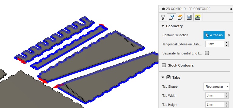
I did this in three parts to my six components.
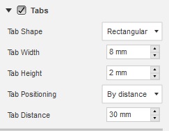
I marked Tabs to add tabs on the edges of pieces to avoid the pieces moving. I set tab width 8 mm, height 2 mm and distance 30 mm.
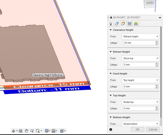
In Height section I chose Model top as top height and selected one face of the bottom surface as bottom height. I checked the bottom height is -11mm.
Then I simulated the tool paths with Actions/Simulate.
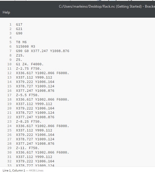
Action / Post Process converts the data of the tool paths as NC code for the CNC machine. I selected personal posts, FabLabCNC.cps as post processor and saved the file as Rack.nc.
CNC Machining
First I turned on the main switch and power on. Then I set up the table (with help of Michael). I attached the OSB board on the table with screws, close to edges so that the machine will not cut the screws.
I used 8 mm flat bit that was already attached by Perttu, he did the cutting just before me.
Next I opened the control SW and set the origins.
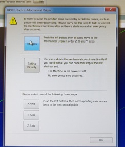
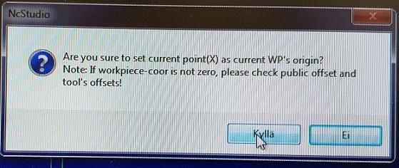
I moved the router with XYZ arrows on the screen. When the bit was in good XY position I zeroed X and Y as origin. Next I calibrated Z axis. I placed the mobile calibrator under the bit and lowered the bit about 10 mm above the calibrator with hand wheel. Next I select Operation -> Mobile calibrator. The software did the calibration of the Z origin.
After that I run the simulation to see how the router would cut the components.
I cleared the previous movements recorded on the screen (right click -> clear).
![]()
Then I opened my Rack.nc file (File -> Open and load) and clicked simulation.
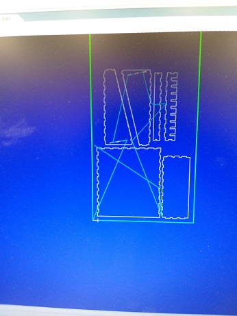
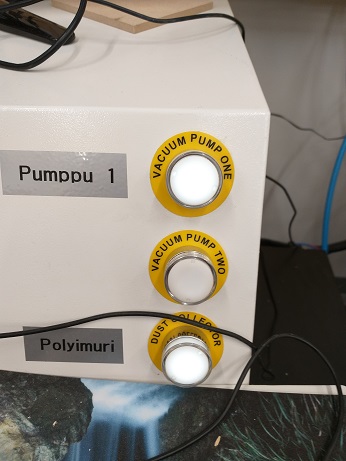
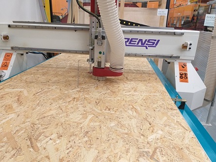
Simulation looks good. Next I turned the vacuum and dust collection pumps on and clicked Start.
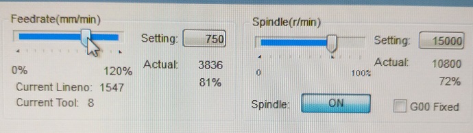
I adjusted the feedrate to 3836 mm/min, which is 81% of the maximum value and spindle rate to 10800 r/min, which is 72% of the maximum value. I changed the values because the machine moved a little too fast, it could be heared from the sound. Too fast cutting might cause a bad cutting trace.
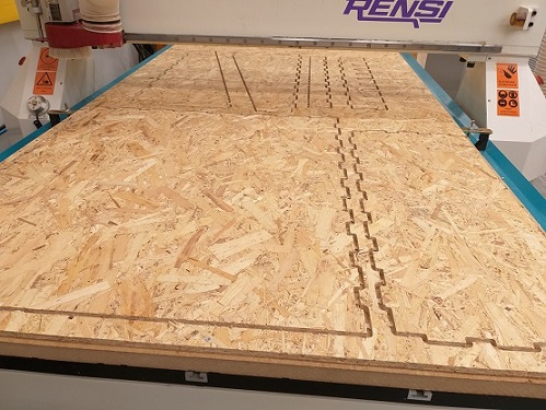
Cutting took about 45 minutes. All parts were cut nicely.
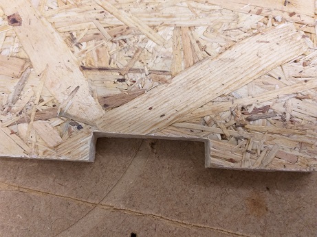
I removed the tabs with carpet knife and filed the edges to remove the sharp splinters and roughness.
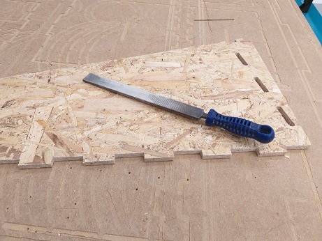
I also filed the round edges in the finger joints to sharp so that the components can be combined.
I could have used dogbone fillets for the joints to avoid the filing of the round edges. When using dogbone fillets the cnc machine overcuts the corners by the radius of the tool so that any mating material will be able to slot into place.
There is an addin for Fusion 360 to create dogbone joints. Also Vcarve can be used.
For visual reasons I decided not to use dogbone fillets.
I put the parts together, with help of Arash, thank you!
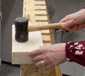
and here is the rack