Final Project
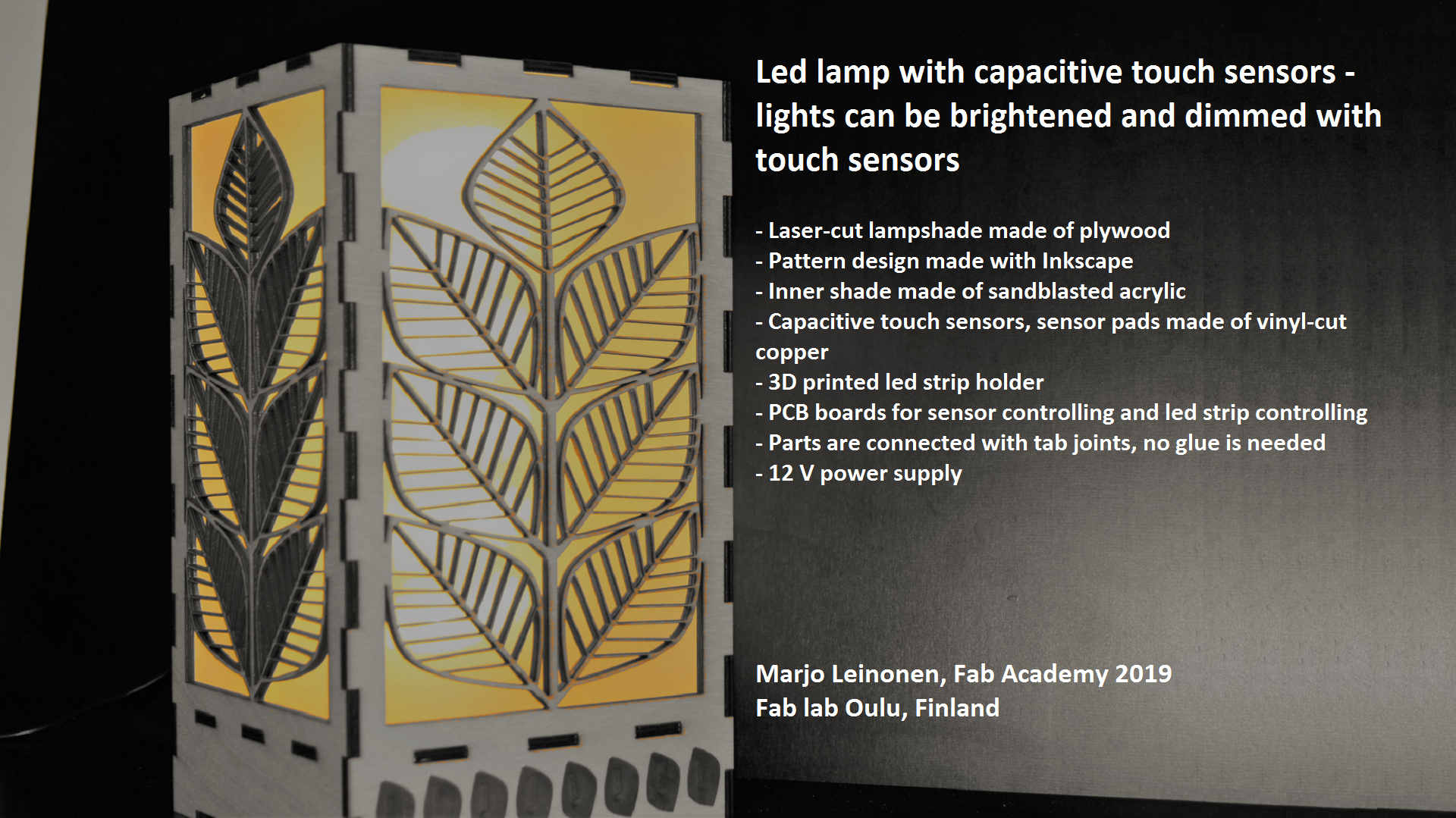
My final project is a led-lamp with plywood laser cut shade. My first idea was to create some kind of cat treat robot, that would be of course for the joy of my two lovely cats. But then I participated in Science Hack Days in University of Oulu, that was on 11.-13.01.2019. This inspired me to do something beautiful using plywood and laser-cutting. With a little bit thinking and exploring in web I decided to create a led-lamp that has some sensors for interactive use.
In my first idea the lamp has a sensor that turns it on and off using voice command. OR, I got this alternative idea for instructors in Oulu, I could have capasitive On and Off buttons like in Fab Boombox created by Matt Keeter. Another sensor will adjust the brightness of the light depending on the intensity of the light in the room.
This lamp can be used in living room or bed room for decoration and lightning.
Final project requirements
What does it do?
LED lamp has capacitive touch buttons on plywood for dimming the light.
Who’s done what beforehand?
Matt Keeter has done capacitive buttons on plywood Fab Boombox.
What did you design?
2D design
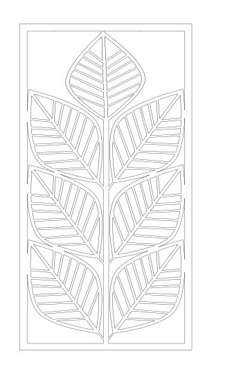
I have designed the shape for laser-cut lamp shade with Inkscape.
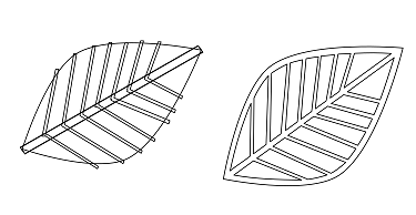
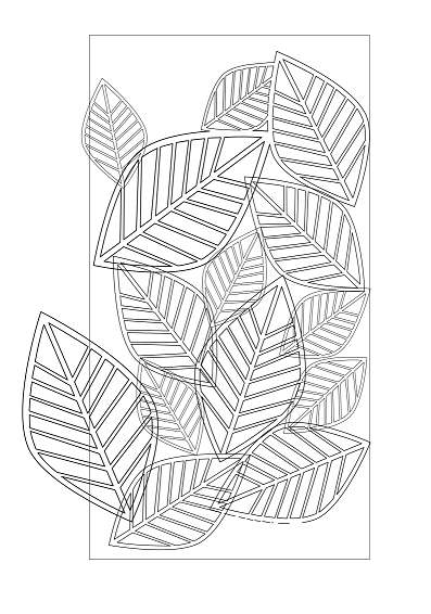
I had some idea in my mind about the pattern I want, but I needed to play around a bit with Inkscape to understand how to draw and what kind of operations could be used. I watched one tutorial about Bezier-lines and learned how to use those. This gave me idea how to use Besier-line tool in my lamp-design. Here are couple of first drafts for my lamp patters:
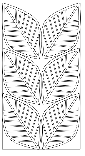
I used the nodes-tool to combine the patters. Here is the final pattern.
3D design
I needed a structure inside the lamp where to attach the led strip. I designed the 3D printed led holder to attach the led strip. The design was done using Fusion 360.
First I created a base and a cylinder.

Then I created a coil to make the groove for the led strip

I set the diameter to 46 mm, 6 revolutions and groove width to be 12 mm (for 10 mm led strip).

After that I made the screw holes for attaching the holder to the lamp and extruded the cylinder to be hollow.

Electronics design
I have designed PCB boards for sensor and led control.

What materials and components were used?
Plywood (4 mm thickness)
Acrylic sheet (3 mm thickness)
LED stripe (80 cm)
Capacitive buttons (copper pads)
Microcontrollers (ATTiny44)
ABS for LED attaching structure
Where did they come from?
Most of the components came from Fab Inventory. Led strip was bought from local store SPElektroniikka.
How much did they cost?
BOM of Led control board:

BOM of sensor board:

Plywood 0.4 m2: 10 Eur
Acrylic 0,4 m2: 10 Eur
Led strip 1 m: 4 Eur
Copper pads: 3 Eur
Power supply 12V: 10 Eur
3D printing material (ABS): 1 Eur
Total: 52,85 Eur
What parts and systems were made?
Lamp shade is made with laser-cutting.
Lamp inner shade is made with laser-cutting and sand blasting to get mat surface.
Led attaching structure is made with 3D printing.
Touch sensor board and led control board are made by milling and soldering.
Sensor pads are made by vinyl cutting.
What processes were used?
- Laser-cutting, 2D desing and 3D design for the shades.
- 3D printing and 3D design for the led attaching structure.
- Electronics design, milling and soldering for the PCB boards.
- Embedded programming of the capacitive touch buttons and led controlling.
- Vinyl cutting for the copper sensor pads.
What questions were answered?
How to program the eight sensors to get smooth dimming? The logic of the sensor function needs to be decided. I am having eight sensor pads. What will happen when touching one of them? Will it depend on the order the pads are touched? I ended up having sensor pad1 for the “lights off”, sensor pad2 for dim light and sensor pad8 for the brightest light. And pads 3-7 something in between.
How was it evaluated?
When touching the sensors you are able to brighten and dim the lights. Sensor pad1 (on the right) will switch the lights off. Sensor pad2 will have a dim light and with pads 3-8 you get the light brighter.
The lamp will be ready to be used at home.
What are the implications?
During Applications and implications week I made a summary of my Final project, what has been done so far.
Your project should incorporate
- 2D and 3D design -> lamp shade and Led attaching structure
- additive and subtractive fabrication processes -> 3D printing for led attaching structure and laser-cutting for the shades
- electronics design and production -> PCB boards
- microcontroller interfacing and programming -> capacitive button and controlling the buttons and leds
- system integration and packaging -> assembling the lamp
2D and 3D Modeling
Here is the first sketch:

Here is the 2D design of the lamp shade, this will be laser-cut of plywood:
This is a 3D sketch to see how the lamp will look like:
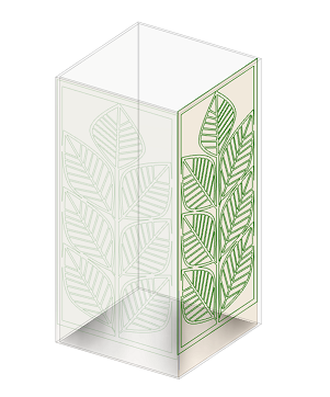
I created also a detailed design with Fusion 360 to understand the lampshade structure with the midsole (electronics is hidden under that).
See week03 for detailed description.
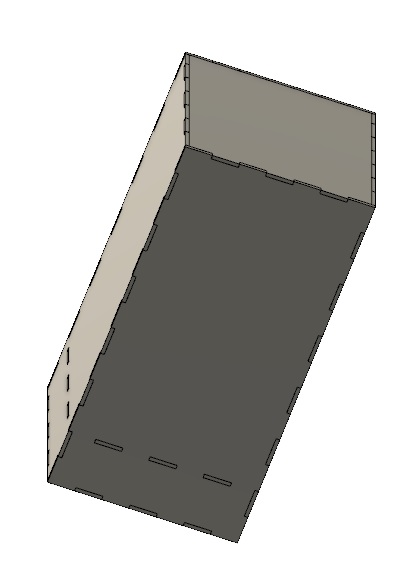
In the end I noticed that the Inkscape pattern is easier to combine into lampshade parts when having the lampshade box also designed in Inkscape. So I created to final box parts in Inkscape.
Electronics
Led control board
I used the PCB board design from week12 with some modifications. I added a diode to protect the regulator and changed VCC and GND connections of the power jack (to be as normal order).
FTDI pins in Led control board are used to connect to Touch sensor board (giving 5V power to touch control board and taking sensor signals from touch control board).
Sensor board
I used the PCB board from week11.
I modified the sensor code to work in serial mode with the Led control board.
Sensors
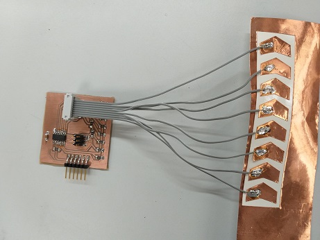
I re-designed the copper sensors using Inkscape and cut the sensors with vinyl cutter. I used the same process than on week04 vinyl cutting assignment.
First I cut thin copper strips to make the contact between sensor pads and sensor board.

Then I cut the sensor pads and clued them on the lamp using transfer sheet.

I soldered the sensor strips to the cable I created to make the connection between sensor pads and sensor board.
I added screw holes in my PCB boards so that I can attach PCB boards to the lamp. It is only now when I was able to define the exact location of the holes. I used drilling machine to drill two 3mm holes to both of them.

Assembly
First I glued led strip to the groove in led strip holder. Next I screwed the led strip holder and PCBs to the divider. Then I assembled the rest of plywood parts, without bottom and top parts. Laser cut parts have tab joints and they were easy to combine. Joints are very good, no glue is needed.
Next I combined the acrylic parts and put the box inside of the plywood box. I attached the top part with the tab joints.
I connected the PCB boards with the cable I made and connected the sensors to the sensor board.
Finally I closed the bottom part and the lamp is finished!
Testing
I tested the lamp by connecting 12V power to the lamp and by testing the touch sensors. It seems that the capacitive sensors are causing interference to each others and the sensor pads are not working as they should. This needs to be corrected.
I can make the correction with sw modification. I need to change the treshold values so that only the finger touch will give the impulse to led control board. I tested the values that are sent when touching the sensors and printed the values in serial monitor. It was clear that when sensor was touched, the value is always a lot more than 200, around 300. And the neighbour button values with interference are below 100. I changed the threshold value to 200 in the code. I uploaded the updated code in the sensor board and now the buttons (touch sensors) are working correctly! I am able to brighten and dim the lights.
License
In week19 assignment I familiarized myself with different kind of licenses and chose the one that suits for my Final project.
I am choosing Creative Commons with ShareAlike and NonCommercial for the non-software part of my project:
ShareAlike (sa)
You let others copy, distribute, display, perform, and modify your work, as long as they distribute any modified work on the same terms. If they want to distribute modified works under other terms, they must get your permission first.
NonCommercial (nc)
You let others copy, distribute, display, perform, and (unless you have chosen NoDerivatives) modify and use your work for any purpose other than commercially unless they get your permission first.
Presentation material
Presentation slide
Presentation video
I used Open Shot video editor for editing the video and compressed it with HTML5 MP4 ffmpeg encoding
I used variable bit rate 1080p MP3. In command prompt I used command
ffmpeg -i input_video -vcodec libx264 -crf 25 -preset medium -vf scale=-1:1080 -acodec libmp3lame -q:a 4 -ar 48000 -ac 2 output_video.mp4
Photos and video clips used are taken by Marjo Leinonen and Gleb Bulygin.
Music is by David Szesztay from Freemusicarchive.
Project development
Project development week was the last step to check how is my Final project proceeding against the plan.
I noticed that I have pretty good status, I have only some minor things left and the time management has succeeded well for me.
Files
Led control board, Eagle schematic
Led control board, Eagle board
Touch sensor board, Eagle schematic
Touch sensor board, Eagle board
Led control code
Sensor code
Sensor pads, Inkscape file
Sensor strips, Inkscape file
Acrylic lamp shade, Inkscape file
Lamp shade part 1, Inkscape file
Lamp shade part 2, Inkscape file
Lamp shade part 3, Inkscape file
Lamp shade part 4, Inkscape file
Lamp shade part 5, Inkscape file
Lamp shade part 6, Inkscape file
Lamp shade part 7, Inkscape file
Led strip holder, stl file
Led strip holder, Fusion 360 file