14. Networking and communications
Group assignment:
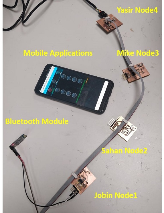
The group work was done together, four boards were used as separate nodes. The plan was to communicate with Bluetooth module. We named the nodes as Jobin_Node1, Sahan_Node2, Mikel_ Node3 and Yasir_Node4. All the boards we programmed and connected serially, and controlled through Bluetooth application.
Target was to blink the LEDs on the boards when a button on the Bluetooth mobile application (Bluetooth Control Lamp) is pressed. The LED on each board lit up when the letter corresponding to the number assigned to the node was pressed. Finally, the code was modified so that all the LEDs turned on and off at the same time.
See the below picture of all separate boards connected using serial bus and controlled wirelessly using Bluetooth module.

And a video how it works:
See the code used in Jobin’s page.
Individual assignment:
Design, build, and connect wired or wireless node(s) with network or bus addresses
Individual assignment
First I needed to think how to start the assignment. As basis I took the picture Neil drew in the class.
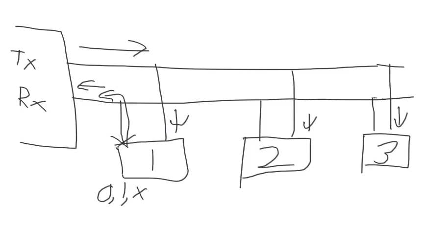
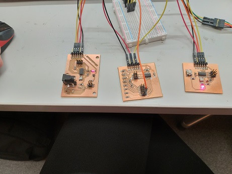
I decided to use three boards to build the bus. I noticed that I can use the PCB boards from previous week; week07, week11 and week12.
I named the boards in the following way:
Node1 (Sensor board from week11), 8 kHz internal clock, no led
Node2 (Led control board from week12), 20 kHz external clock, with led
Node3 (Button board from week07), 20 kHz external clock, with led
I used Jari Uusitalo’s assignment as an example.
I used Arduino IDE for the programming. I modified the codes (NWC_node1, NWC_node2 and NWC_node3) to fit my board pins, actually with ATTiny44 they are the same that Jari has with his ATTiny44.
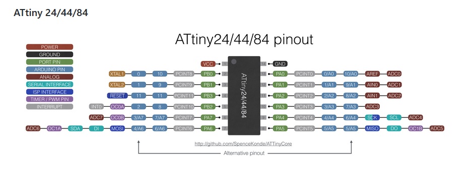
ledPin = 8; // the number of the LED pin ( = ATTiny pin 5)
RX = 0 // Attiny pin 13
TX = 1 // Attiny pin 12
I programmed the boards using the same procedure as in week07.
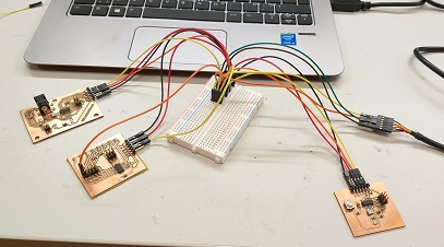
Next I connected the programmed boards to bus using breadboard and jumper cables. I carefully checked that all GNDs, VCCs, RXs and TXs are correctly connected. Then I opened Serial monitor and changed baud rate to 9600 (like in the code).
I typed “2” in the Serial monitor and pressed “Send”. Both boards with led were activated and the leds blinked at the same time. But nothing was shown in the monitor. Next I typed “3”. Again both leds blinked, this time also text appeared to the monitor.
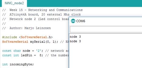
Now I need to study what is wrong. Clearly node 3 is recognized, but node 2 not.
I needed some advice from our instructor Juha-Pekka. He suggested that I could test the boards individually with Led blinking code to check the board clock frequency. I uploaded a blinking code with 1000 ms interval to my boards having led. I found out that my Button board had 8 MHz clock, not 20 MHz that I thought. When I uploaded the code to the Button board with 20 MHz settings in Arduino IDE, the blinking of the led was much slower than 1000 ms interval. When I changed the settings to 8 MHz, the led was blinking with 1000 ms interval.
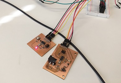
I decided to use in my networking assignment only the boards with leds. I renamed the boards:
Node1 (Led control board from week12)
Node2 (Button board from week07)
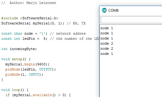
I uploaded the codes (NWC_node1 and NWC_node2) to the boards and connected the boards to bus using breadboard and jumper cables just like earlier. I opened Serial monitor in Arduino IDE and send “1”. Node1 board had the extra blink and text “node 1” was showing in serial monitor. When sending “2”, Node2 board had the extra blink and text “node 2” was showing in serial monitor. When sending something else, e.g. “3” or “a” no extra blinking was showing or no text.
The code defines the network address for the nodes, in the following the address for Node1 is “1”.
const char node = '1'; // network address
Later the serial data is read in to the variable “incomingByte”
incomingByte = mySerial.read();
If the read data is = node address, the led will be set on
if (incomingByte == node) {
      digitalWrite(ledPin, HIGH);
Reflections
With embedded programming there are many possibilities to make an error and you need to be very careful when building the system. Know your HW and do systematic step-by-step testing to find the errors. Otherwise simple things may take a lot of time. In my case I assumed that I have 20 MHz clock in my Button board, but testing it showed that it actually was 8 MHz clock.