Interface and Application Programming

  • group assignment: compare as many tool options as possible

    #Tkinter#Processing#Blynk

  • individual assignment: write an application that interfaces a user with an input and/or output device that you made

    #MIT App Inventor#Arduino IDE#Processing#

Group Assignment


I was in the group with Zhengya Gong, Yazan Barhoush, Noora Nyberg and Xinhui Hu. We tested Tkinter, Blynk for Python and Processing for this assignment and published it on Yazan's page Interface and Application Programming.

MIT App Inventor


In quarantine days I had only an Arduino kit and no own boards. Therefore, at first I developed the App using Arduino and after I made my own PCBs I have updated the assignment.

Having an Android device, I decided to make an application with MIT App Inventor. All the instructions on how to get started building the application for the phone are given on this page, plus there are thorough tutorials also provided by the MIT App inventor team, making it easier to start for beginners.

The best option is to have an Android device connected to a computer via WIFI. At first I downloaded and installed the MIT AI2 on my phone.

To start the App development:

  • Create Apps! button =>
  • Start new project (give it a name) =>
  • Connect => AI Companion =>
  • Scan QR or enter the code =>
  • Now the application will appear on a phone screen and will follow all the changes introduced on a web page.
... ...

Fig 1. Starting new application in MIT App Inventor and connecting to the phone.

LED ON/OFF App


My first steps with MIT Inventor I took with help of the basic tutorial - App to control the LED light. I think with further improvements it can be used to control the backlight of the XY stage. Some helpful instructions can be found here.

The idea is that the LED will be turned ON and OFF by clicking the button of the application on the phone. The App will be sending the serial data to Arduino via HC-05 Bluetooth module, which will transfer this data through the TX pin to the RX pin of the Arduino. The code is written in a way, that '0' or '1' send to Arduino will be pulling the strings "LED: ON" and "LED: OFF" correspondingly.

It is important to remember, that sketch should be uploaded to Arduino with RX and TX disconneted with Bluetooth module. Disconnect the HC-05 bluetooth module Rx and Tx pins from Arduino Uno as this particular board has only one hardware serial and connecting something to it while uploading a sketch will create conflict or your can using Arduino SoftwareSerial to avoid conflicts. Reconnect these pins once you are done uploading the sketch.

Hardware components

  • Bluetooth Module (HC-05)
  • Arduino Uno
  • LED
  • Resistor(220 ohm)
  • Breadboard
  • Wire jumpers

Circuit

  • Bluetooth Module(HC-05):
    • VCC to 5V (Arduino UNO)
    • GND to GND (Arduino UNO)
    • TXD to 0 (RX)
    • RXD to 1 (TX)
  • LED anode (+ long leg) through 220 Ohm resistor to Arduino pin 9, cathode (- short leg) to Arduino GND
...

Fig 2. The schematic of Bluetooth module connection with Arduino

The Arduino IDE sketch for LED ON/OFF via bluetooth:


#define ledPin 9
int state = 0;

void setup() {
 pinMode(ledPin, OUTPUT);
 digitalWrite(ledPin, LOW);
 Serial.begin(9600); 
}

void loop() {
 if(Serial.available() > 0){ // Checks if data is comming from the serial
 state = Serial.read(); // Reads the data from the serial port
 }
 
 if (state == '0') {
 digitalWrite(ledPin, LOW); // Turn LED OFF
 Serial.println("LED: OFF"); // Send back, to the phone, the String "LED: OFF"
 state = 0;
 }
 
 else if (state == '1') {
 digitalWrite(ledPin, HIGH);// Turn LED ON
 Serial.println("LED: ON");// Send back, to the phone, the String "LED: ON"
 state = 0;
 } 
}
  

MIT Application development starts in the Designer mode. The list of the main components for the App is on the left Palette menu. The structure with all the components used is on the right Components menu. Individual properties of each component can be adjusted in the Properties menu. Invisible components appear on the bottom of the Screen menu. I started from Layout arrangement on the left panel menu and added the HorizontalArrangement. It's properties the height, width, alignment, color etc. can be set up on the right menu pallete Properties. I used in total 6 HorizontalArrangements, which I then filled with the required components.

The main components of the App from the User Interface Palette:

  • List Picker is used for selecting the Bluetooth device to which the phone will connect (I made the image for this component)
  • Label will show the status of Bluetooth connection (Connected / Disconnected)
  • Buttons 1 and 2 to control the state of LED ON/OFF
  • BluetoothClient to connect the phone and Arduino via Bluetooth
  • Clock real time indication of the connection status

I've created the simple image for the ListPicker component and uploaded it in the Media on the bottom right, and chose this image in the ListPicker Properties menu.

...

Fig 3. Designer editor of MIT App.

After finishing the "look" of the App, I assigned the function for each component in the Block editor (upper right corner) from the left menu.

  • "BeforePicking" block with an attached "ListPicker" block and "BluetoothClient AddressesAndNames": will show the list of the paired devices with a phone, when the "Connect" Bluetooth button is pressed.
  • When the Bluetooth module is chosen from the list in the "ListPicker" "AfterPicking" block, the "call BluetoothClient" with "Connect address" and "BluetoothList Selection" blocks attached will connect the smartphone to the previously selected Bluetooth address.
  • "Timer” block is a function checking whether the phone is connected (label "Connected") or not (label "Disconnected") to the Bluetooth module. It is executed periodically every TimerInterval, which is by default the is set to 1000 milliseconds (1 second), and "TimerAlwaysFires" (stays active).
  • When the Button1 is clicked, the Text 1 (LED ON) will be send to Arduino, clicked Button2 will send Text 2 (LED OFF).
...

Fig 4. Functions for the components in the Blocks editor of MIT App.

The Application can be connected to the phone through the phone MIT App Inventor App at any time by Connect -> AI Companion and scanning the generated QR code. The installation of the App is the same simple, only code is generated with Build -> App. It is important to check the restrictions for applications installation on the phone. Also, before trying to connect with a bluetooth module, try to find it first without using the App. My App couldn't see the device before I didn't pair it in Bluetooth settings of my phone.

...

Fig 5. Generation the codes to Connect AI Companion and to Build the App to install on the phone.

...

Fig 6. Connecting to Bluetooth with the application installed on the phone.

LED brightness control


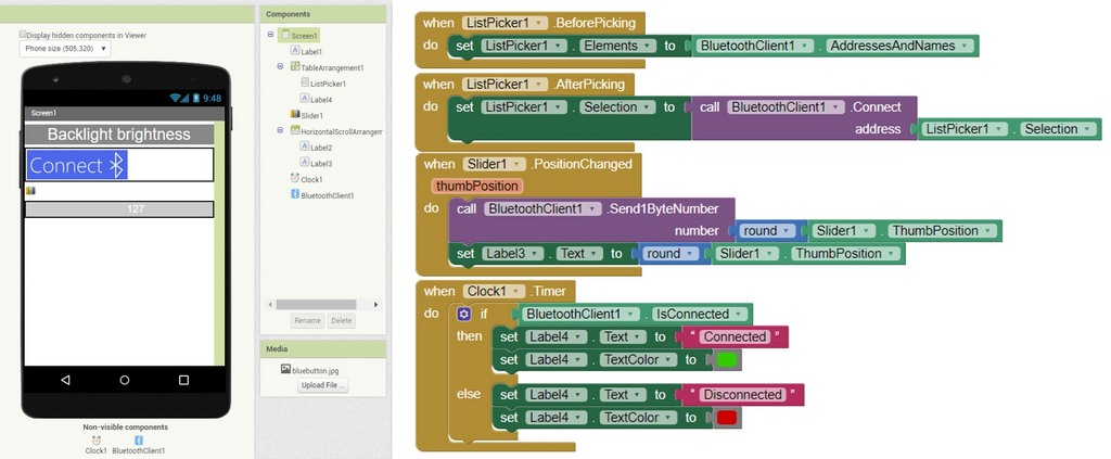
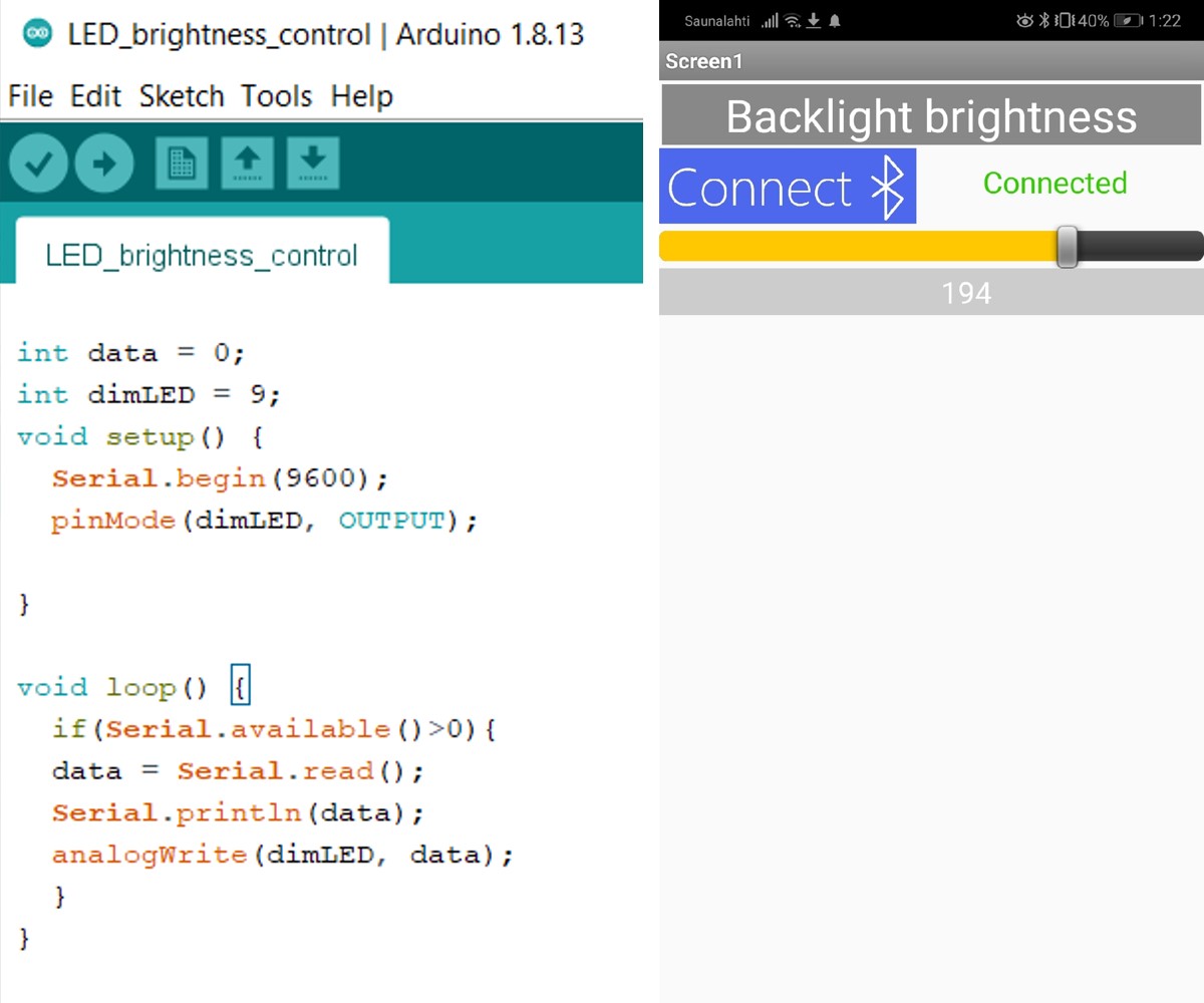
I have also made another application to control the brightness if the LED, applying almost the same steps. I used the simple Arduino code, plus Slider component, and the Label indicating the level of brightness from 0 to 255. LED is connected to Arduino pin 9.

Arduino code is sending the data from the pin 9 to serial port. I used the element Slider in the application. The default Slider settings are Minimum 10.0, Maximum 50.0 with an initial slider setting of 30.0. For use in controlling the LED, the minimum is set to 0 and maximum 255.

...

Fig 7. Designer and Blocks editors of MIT App Inventor - Application to control the brightness of the LED.

...

Fig 8. Arduino Sketch and working Application from the phone screen.

The Arduino IDE sketch for LED brightness control via bluetooth:


int data = 0;
int dimLED = 9; 
void setup() {
  Serial.begin(9600); // initialize serial communications at 9600 bps:
  pinMode(dimLED, OUTPUT); //configure pin 9 as an output

}

void loop() { 
  if(Serial.available()>0){ // send data only when the data received
  data = Serial.read(); //read the data from the serial port
  Serial.println(data); //print the results to the serial Monitor
  analogWrite(dimLED, data);// set PWM for LED brightness 
  }
}
  

Processing Joystick Interface


Processing is a software and a language to create the code the tool can be made to communicate with Arduino boards from a computer device by using serial communication to send data from processing to Arduino. The Serial library reads and writes data to and from external devices.

I decided to make the simple interface in Processing for my Atmega328P board.

Atmega328P will be used to retrieve the values from the Joystick and send them in the Serial monitor, and then Processing will be used to display these values, particularly the joystick position.

The joystick position will be represented as a dot on the screen, on the background showing 4 main directions: left, right, up, and down. Joystick positioning in a certain direction will be followed by the text appearing in the center indicating the direction.

In the Arduino IDE sketch the board is programmed to send values of x-axis, y-axis and switch (button state) on serial port. The data are comma-separated, as it was advised in the example, since it is the popular format for transferring data from one application to another.


int xValue = 0 ; // read value of the X axis  
int yValue = 0 ; // read value of the Y axis  
int sValue = 0 ; // value of the button reading 

void setup()  
{ 
  Serial.begin(9600) ;
  pinMode(17,INPUT) ; // Configure Switch as an input
  digitalWrite(17,HIGH); 
} 

void loop() 
{ 
  // Read analog port values from the pins 18 and 19  
  xValue = analogRead(18);  
  yValue = analogRead(19);  
  sValue = digitalRead(17); // Read the logic value on Switch

  // We display our data separated by a comma 
  Serial.print(xValue,DEC);
  Serial.print(",");
  Serial.print(yValue,DEC);
  Serial.print(",");
  Serial.print(!sValue);

  // We end with a newline character to facilitate subsequent analysis  
  Serial.print("\n");

  delay(100);  
}
  

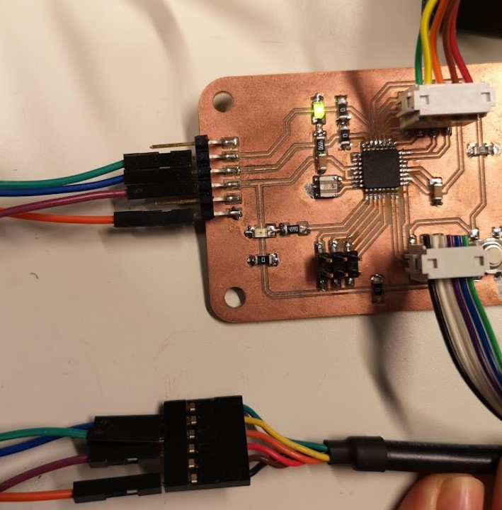
The board connection with joystick and programming are described here. I had a problem with board programming, programming seemed to be done, however no data appeared on the serial monitor. It turned out, that problem was in the FTDI cable I use, it's Rx and Tx were swapped, so I had to changed them, and everything worked out.

...

Fig 9. Board programming

The basic processing sketch is composed of two functions, setup() and draw(). Like in Arduino programming, the setup() is called once in the start of the execution, and draw() is called repeatedly during the execution.

  • import processing.serial.* to read the values coming on serial port import serial library
  • Declare x (Rx), y (Ry) and b (switch) values through the corresponding pins of Atmega328P:
    int x;
    int y;
    int s;
  • PImage is variable container for image. I have used the 4 arrows PNG image as a background. To upload the image in the setup function arrows = loadImage("arrows.png") is used. In void draw() loop my PNG "arrows" image will be laying on the top of the white background:
    background(255);
    image(arrows, 0,0);
  • The position of X and Y is displayed as a text:
    text("Y position="+(1023-y),10,20);
    text("X position="+(1023-x),10,40);
    textSize(20);
  • When the button switch is pressed, the circle will change the color from pink to green:
    if (b == 1){
    fill(#52ecb4); //fill green when SW is pressed
    ellipse(x/2,y/2, 100, 100);
    }
    else
    {
    // Draw a circle with a certain coordinates
    ellipse(x/2,y/2, 50, 50);
    }
  • When the joystick is moved to different positions, the text in the center indicated the diresctions, for example, circle will become blue if the joystick moved right, and the text "RIGHT" will apper in the center:
    if (x > 550){
    fill(#047bbe); //fill blue when x > 550
    ellipse(x/2,y/2, 50, 50);
    text("RIGHT",230,256); }

Processing IDE code:


import processing.serial.*; //import the Serial library
Serial myPort;// Create object from Serial class

PImage arrows;
int x; // variable holding the value from pin 18
int y; // variable holding the value from pin 19
int s; // variable holding the value from Switch
String val;

void setup()
{
  size ( 512 , 512 ) ; // window size
  arrows = loadImage("arrows.png");
  // we are opening the port
  println(Serial.list()); // List all the available serial ports
  myPort = new Serial(this, Serial.list()[0], 9600); //open first found port on 9600bps
  myPort.bufferUntil('\n'); 
}


// drawing loop
void draw()
{
  background(255);
  image(arrows, 0,0);
  fill(#e94e94) ; // set the fill color to pink
  noStroke();
  
  text("Y position="+(1023-y),10,20);
  text("X position="+(1023-x),10,40);
  textSize(20);
  
   if (b == 1){
    
    fill(#52ecb4); //fill green when SW is pressed
    ellipse(x/2,y/2, 100, 100);
  } 
  else
  {
    // Draw a circle with a certain coordinates
    ellipse(x/2,y/2, 50, 50);
  }
  
  // we display data
   if (x > 550){
    
    fill(#047bbe); //fill blue when x > 550
    ellipse(x/2,y/2, 50, 50);
    text("RIGHT",230,256);
  } 
  
  if (x < 490){

    fill(#d21d0a); //fill red when x < 550
    ellipse(x/2,y/2, 100, 100);
    text("LEFT",235,256);
  } 
  
   if (y > 550){
    fill(random(255),random(255),random(255));//fill random color
    ellipse(x/2,y/2, 50, 50);
    text("DOWN",230,256);
   } 
   
    if (y < 470){
    fill(#a13da0);
    ellipse(x/2,y/2, 50, 50);
    text("UP",245,256);
   } 
}


// data support from the serial port
void serialEvent( Serial myPort) 
{
  // read the data until the newline n appears
  val = myPort.readStringUntil('\n');
  
  if (val != null)
  {
        val = trim(val);
        
    // break up the decimal and new line reading
    int[] vals = int(splitTokens(val, ","));
    
    // assign to variables
    x = vals[0];
    y = vals[1] ;
    s = vals[2];

  }
}
  

Files:

Reflection

I'm a complete novice in programming, so the task was quite challenging for me. In MIT App Inventor the hardest for me was to work on the blocks, to associate the functions with an Arduino code. I wanted to modify the code for Neopixels to programm my AtTiny44 board, but for some reason it doesn't work properly. I can still try to use Neopixels with Atmega328P board. Processing also requires effort to make something for me, therefore I went for simple functions, however I still coudn't make the function, that when the joystick moved to some direction it would change shape to rectangular, which is rotating.