This week we had do design and produce something big by CNC milling. I started with a design of the stool, however in the middle I decided to switch to table design. After I finished it, I decided I don't need the table... So I ended up trying to make something I may use - the drawer for the balcony.
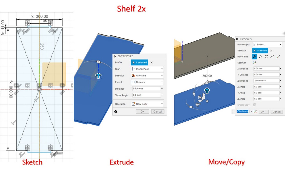
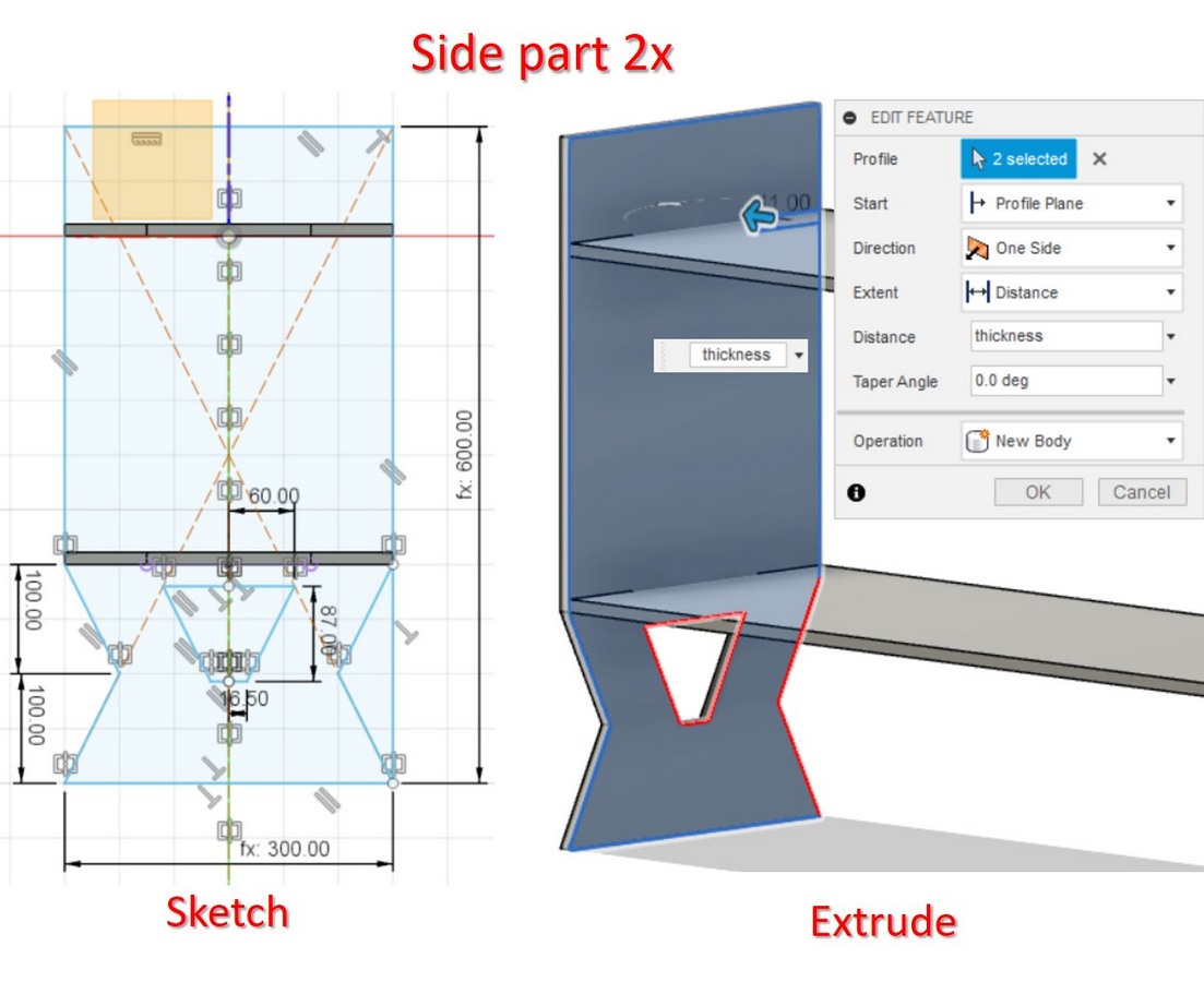
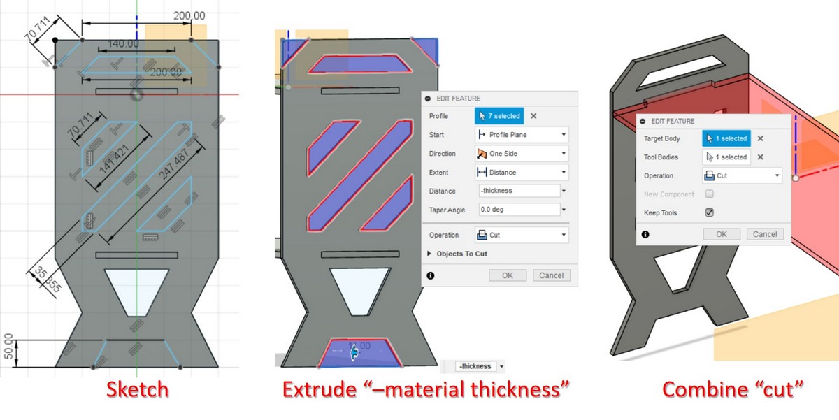
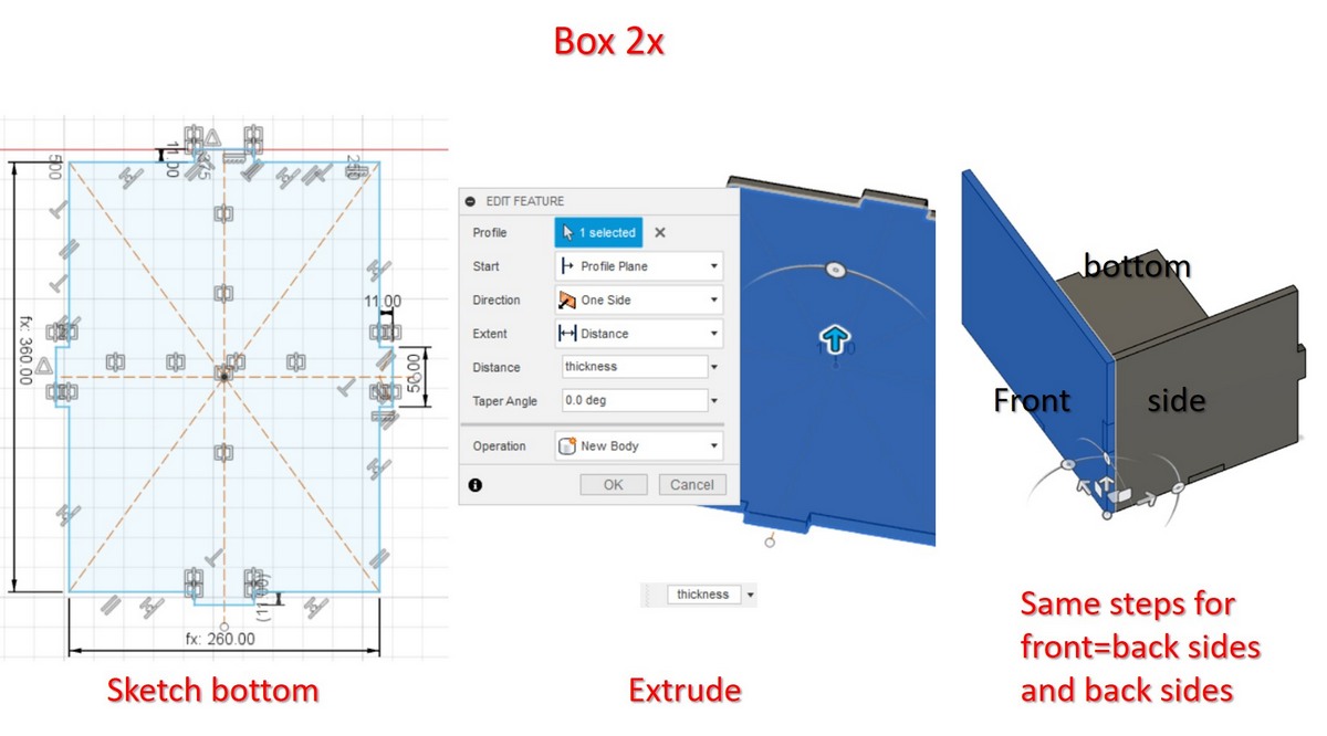
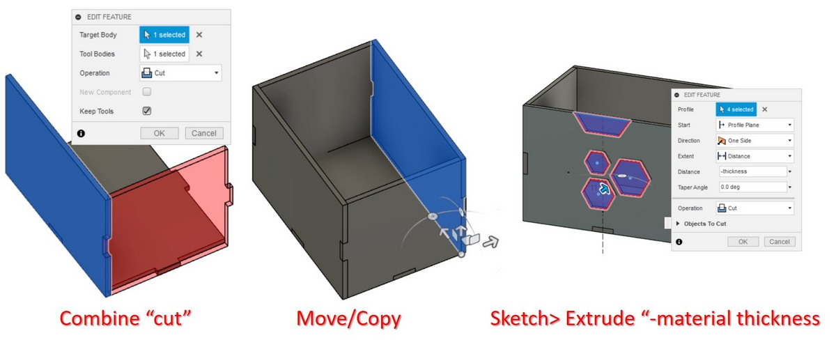
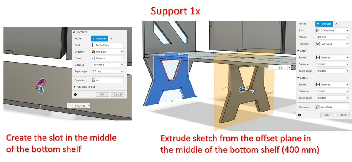
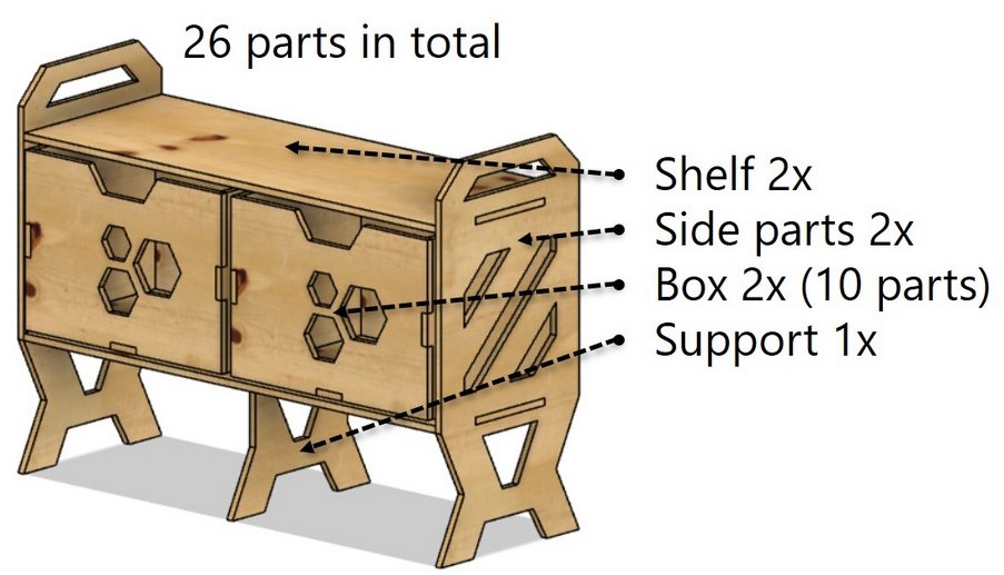
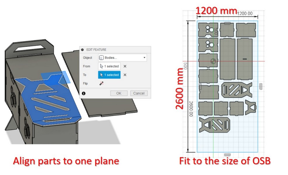
Creating the drawer 3D model in Autodesk Fuison 360:
CAM settings (manufacture in Autodesk Fusion 360)
To create the tool paths (G-codes) for the CNC router we had to download the CAM processor file () and the setting files with values for different milling bits available in our Fablab. Below following the steps to produce the tool paths of the design:
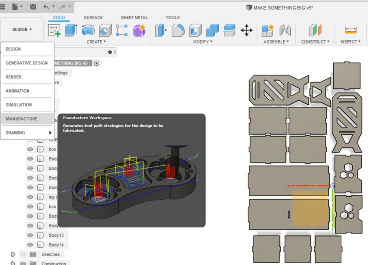
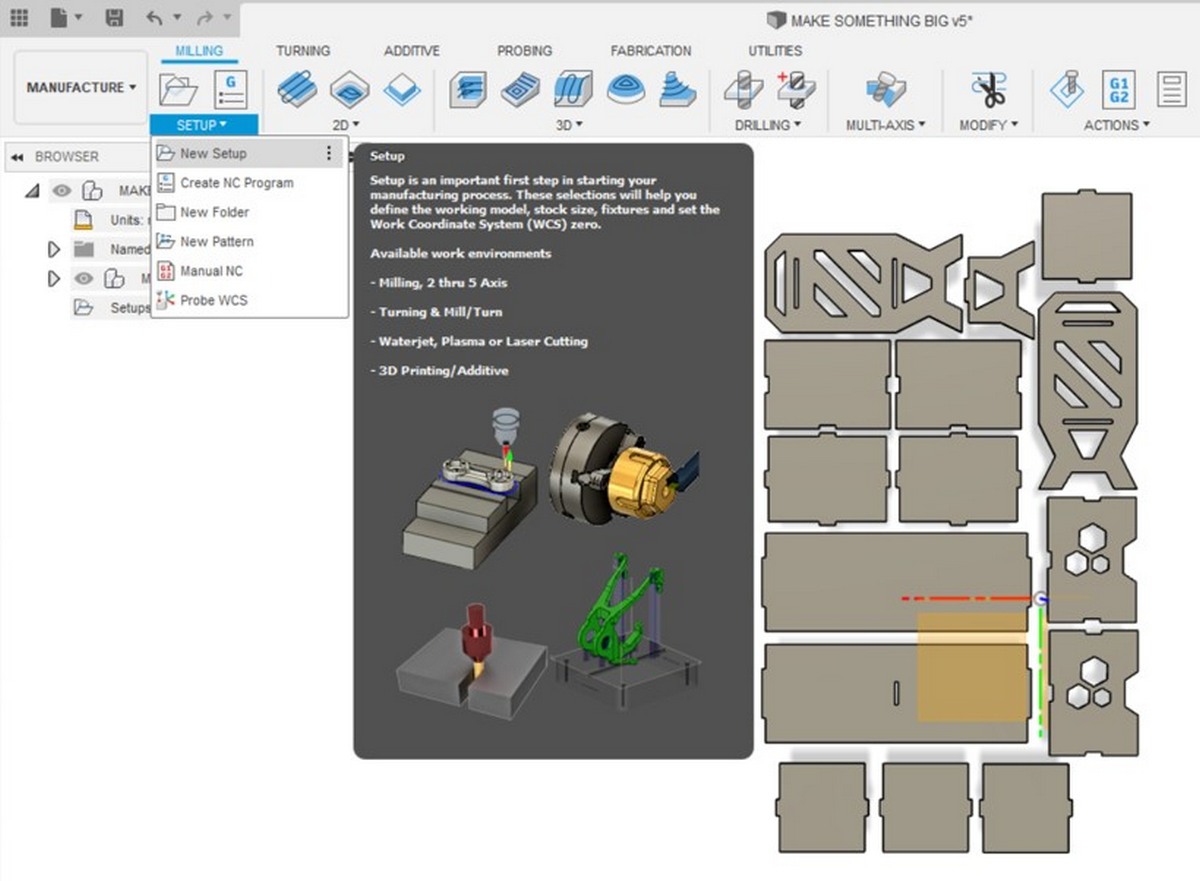
Manufacture Workspace
Fig 3. Open Manufacture Workspace and start the New Setup
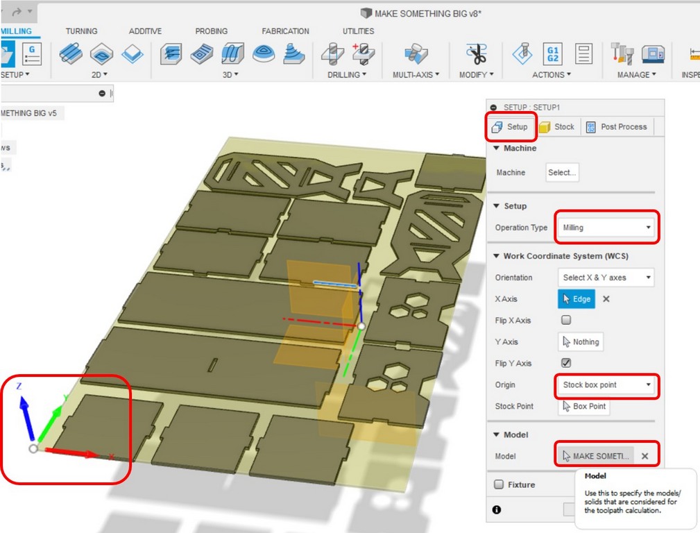
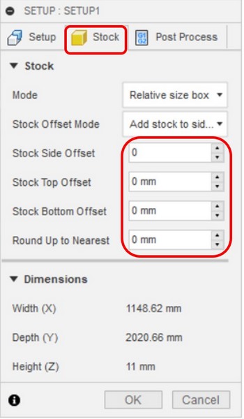
Setup settings
Fig 4. Set highlighted settings in Setup , Stock , Post Process
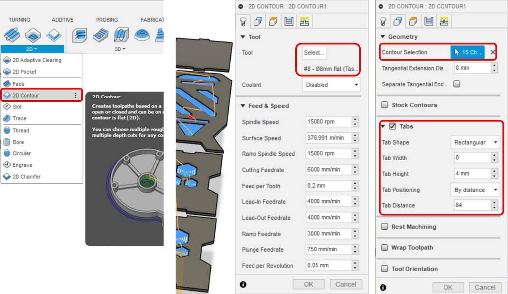
2D pockets
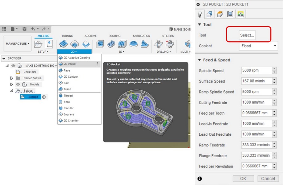
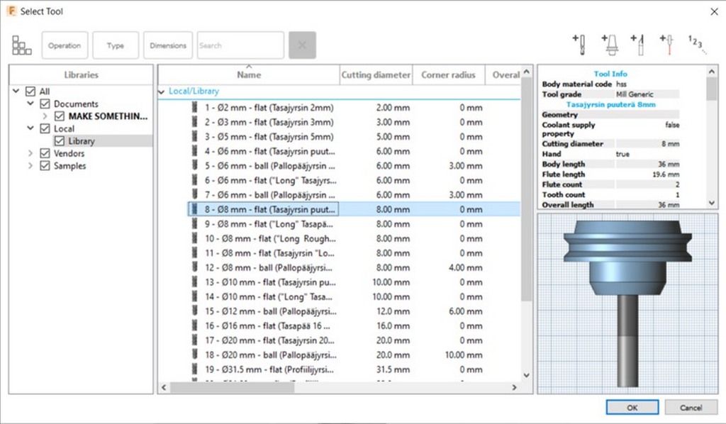
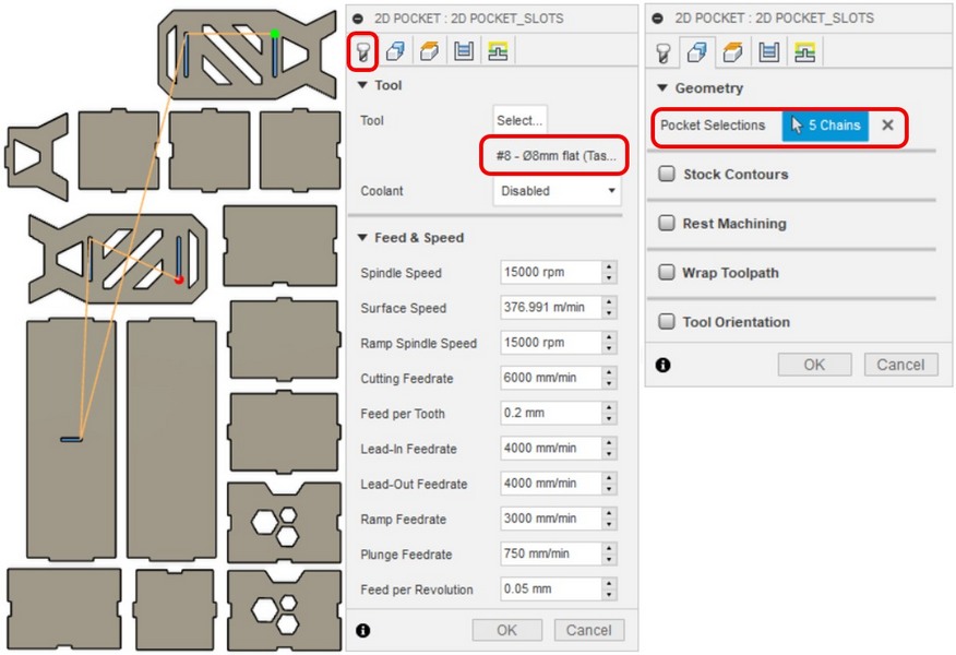
Fig 5. 2D Pocket > Select tool > Download Fablab Library > 8 mm, flat
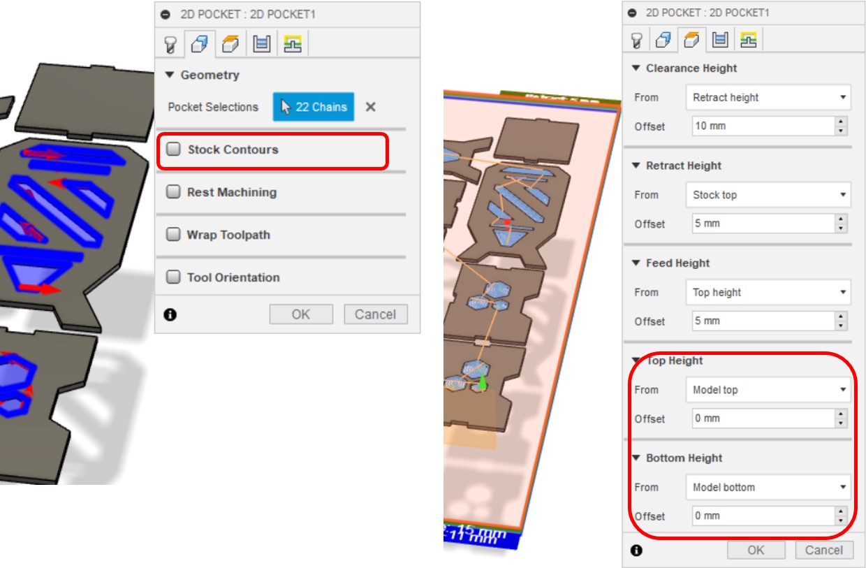
Geometry > Pocket Selection > Select the pockets of the design
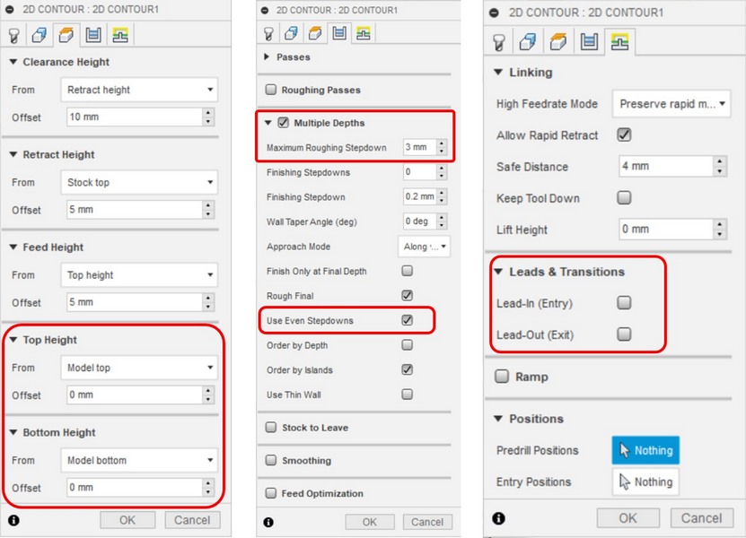
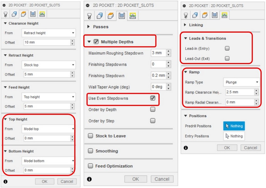
Height > Set the top and bottom heights to Model top and Model bottom
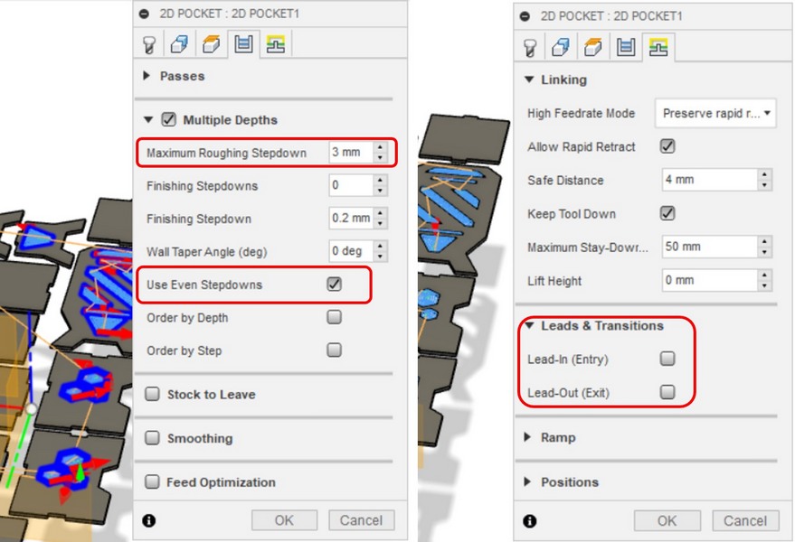
Passes > Multiple Depths > Maximum Roughing Stepdown to 3mm and Finishing Stepdown to 0.2mm > Use Even Stepdowns
Linking > Deselect Leads and Transitions
Fig 6. Geometry, Height, Passes and Linking settings for 2D Pockets
2D pockets
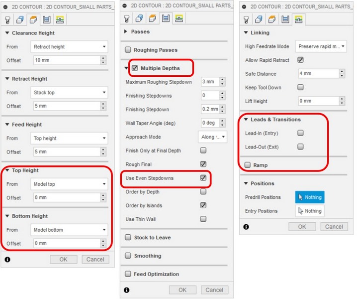
Geometry > Contour Selection > Select the contour of the design
Height > Set the top and bottom heights to Model top and Model bottom
Passes > Multiple Depths > Maximum Roughing Stepdown to 3mm and Finishing Stepdown to 0.2mm > Use Even Stepdowns
Linking > Deselect Leads and Transitions
Fig 7. Geometry, Height, Passes and Linking settings for 2D Contour
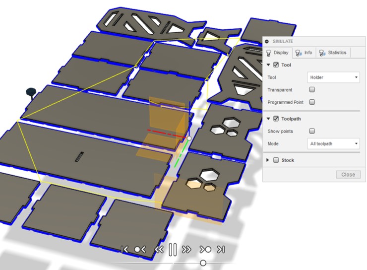
Simulation
Before exporting the .nc file for the CNC router, I ran the Simulation by Actions > Simulate
Fig 8. Simulation of the material removal on the toolpaths
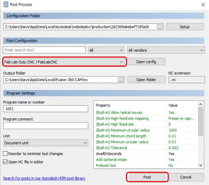
Post Processing
Actions > Post process > Uploaded the FabLabCNC > Post > Gcode was generated
Fig 9. Post processing of the material removal on the toolpaths
Corrections
UPDATES:
After our local instructor Eino checked my files, there are were few issues to fix:
- Some parts of the design we nested too cose to each other, having no space between the toolpaths. The distance between the parts should be around 2.5 cm.
- Add more tabs. Small parts had not enough tabs to keep them attached to the board during the milling process.
- Use "Countour" to cut the holes in the design, instead of the "Pocket", the milling will take 2 mins, instead of 20.
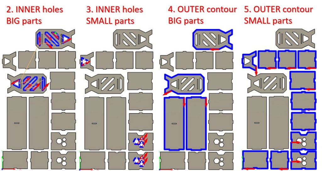
- I need to generate few separate toolpaths in the certain sequence:
- "Pockets" for slots
- "Countour" for the INNER holes of the BIG parts
- "Countour" for the INNER holes of the SMALL parts
- "Countour" OUTSIDE the BIG parts
- "Countour" OUTSIDE the SMALL parts
1. "POCKETS" FOR SLOTS
Fig 10. Settings used to generate the "Pockets" to cut the slots of the design.
2, 3, 4, 5 "CONTOURS"
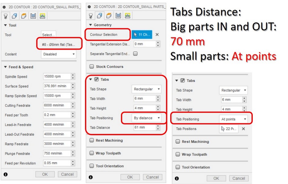
Fig 11. Settings used to generate the "Contours" toolpath of the design.
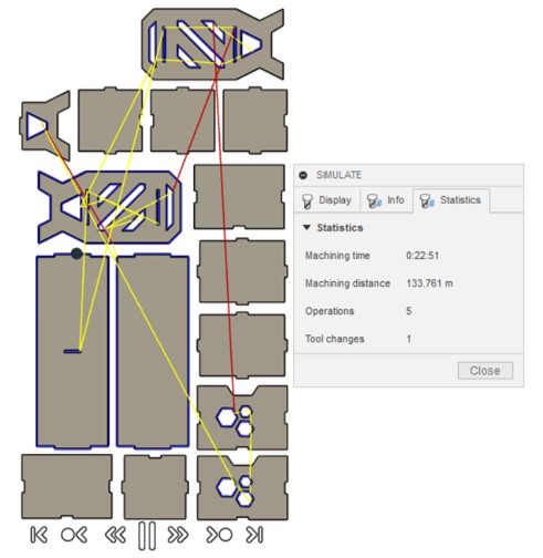
Fig 12. Simulation process, Machining time 22.51 mins.
Machining
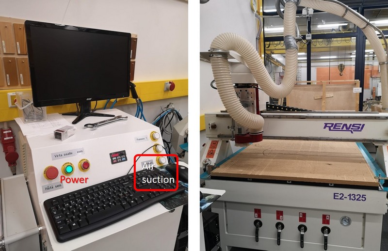
Fig 13. Starting the machine with a power button, and activating the air suction.
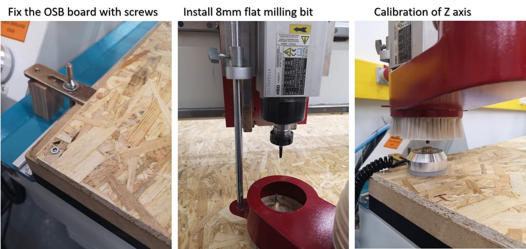
Fig 14. OSB board was fixed with 5 screws, 8mm milling bit was installed, Nc studio > Operation > Fixed calibrator, to calibrate the Z distance.
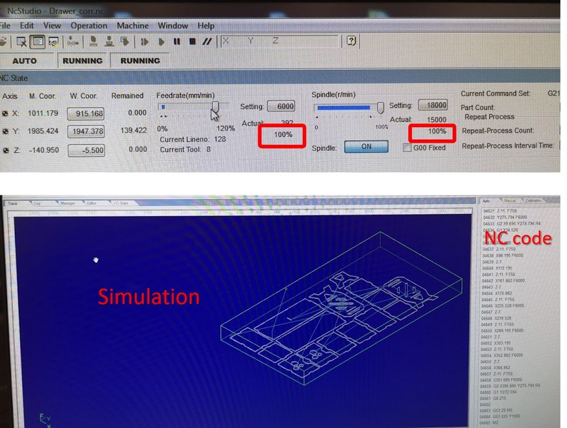
Fig 15. Feedrate 100%, Spindle 100%. Simulation of the process.
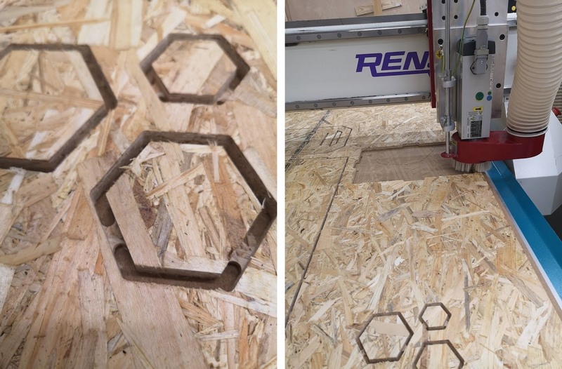
Fig 16. Tabs of the design. In the middle of the procees, the milling bit got stuck in the board. My first thought was that I tight it not secure enough, with my 50 kg power, but it just went too deep for some reason. I stopped the machine immediately, that is why it is EXTRA IMPORTANT TO SUPERVISE THE PROCESS! We checked the code, it looked fine, so after removing the part, we resumed the process from the cirtain code part, where the process was stopped.
Assembling
It was the most challenging part!
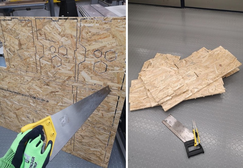
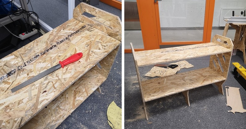
- Tabs of 4 mm height maybe secure choice, but as I expected, removing the parts was physically hard. I had to use 2 types of saws, knife, and, of course, protective gloves. After 1 hour of extensive physical work, parts were ready.
Fig 17. Removing the parts.
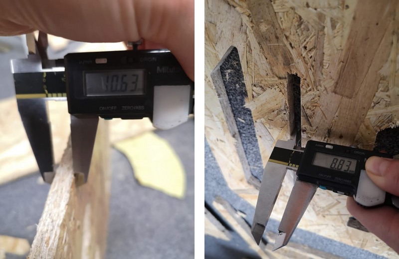
- The bigger issue, my slots were about 3 mm thinner, than material, making assembling impossible... I checked the design, and there slots width was 11 mm, so I still don't understand the reason for such a discreapency.
Fig 18. Measuring the thickness of the material and width of the slots.
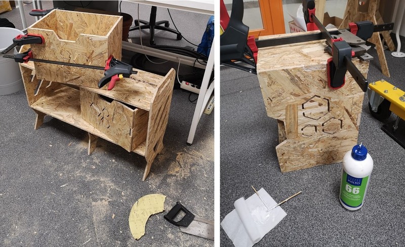
- Gleb to the rescue! Luckily, Gleb has many instruments, he kindly brought the set of the sanding sticks, and since the lab was empty, keeping the distance, we widened the slots and assembled the parts.
Fig 19. My little savior! (here should be photo of Gleb).
Fig 20. We applied the glue to make stiff connections, cleaned the mess, and now have to wait till the glue will completely dry. I didn't remove the polygon parts on the boxes for 2 reasons: 1) I think it looks nice, 2) I had enough;)
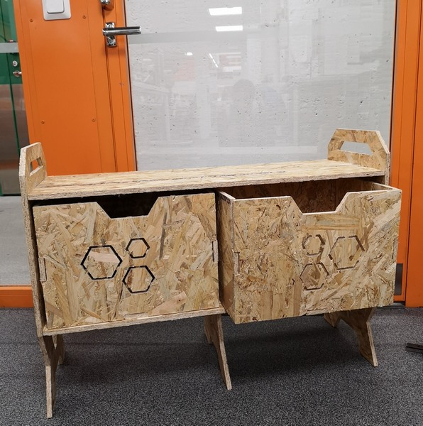
Fig 21. Final result.
FILES:
Reflection
It was interesting, but time consuming process. I started with the design, spent a lot of time choosing among stool, table and drawer. I wouldn't go again for 4 mm tabs height.