individual assignment:
design and 3D print an object (small, few cm3, limited by printer time)
that could not be made subtractively
3D scan an object (and optionally print it)
By printing the same test model on 3 different 3D Printers available at Fablab Oulu: Stratasys Fortus 380mc, Sindoh 3DWOX DP200 and MakerBot Replicator 2, we learned that capabilities of the printers are different.
Comparing the test model quality from each printer, we can choose the printer for our design based on the design rules, in order to get the best result.
Additive design
Additive Manufacturing implies, that material adds during manufacturing to create the object. In comparison to substractive manufacturing, when require to remove the material by other means, such as milling, carving etc. Additive Manufacturing allows to create complex structures from CAD design of 3D scanning, very precisly depositing the material layer by layer.
I have started browsing the ideas on the internet and came accross the complex structures, which hardly can be achieved by other methods rather than 3D printing. These kind of structures are created with computational design tool TISSUE add-on for Blender. I have followed the instructions given on the page to install the add-on. Open Blender Edit> Preferences> Add-ons> Mesh: Tissue> Activate.
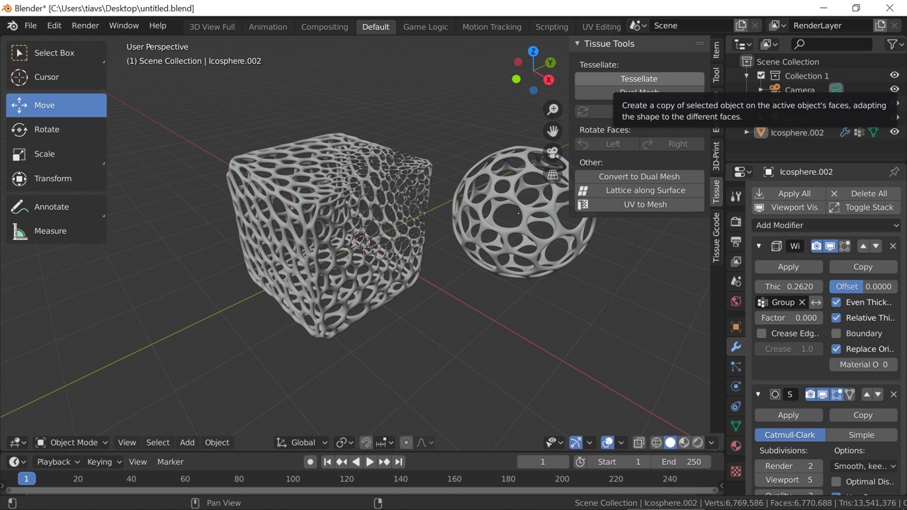
Tool will appear on the right bar as Tissue. I used Tessellate tool, which allows to copy a selected object (Component) on the faces of the active object (Generator). I went through the tutorial to create the box and sphere with Proximity Decimation Technique.
Fig 2. Models created with Tissue add-on for Blender and proximity decimation technique
Eventually I gave up to print these models, as they would not look good anyway with a quality achievable by 3D printers. For that thin structures and small size resolution would not be enough.I found that .STL files exported from Blender were around 600 MB, to upload files here it is unacceptable. I have changed Edit> Preferences> Save and load> Compress File. I also decreased the subdivision of object's mesh. File sizes decreased to 500-700 KB.
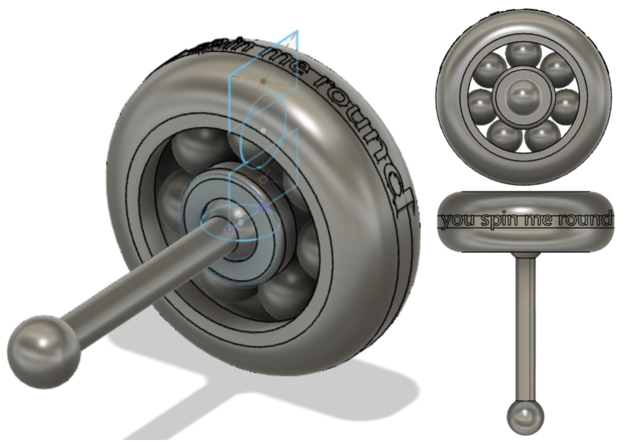
Instead I designed a simple ball bearing in Fusion 360. Basic parts of the ball bearing are balls enclosed between the inner and outer rings (races). Usually balls are held within a special seprator (or cage), but I made the simplified version for 3D printer without the separator. With 3D printing it is possible to make the ball bearing as a whole object, instead of assembling the parts by openning the rings and inserting the balls.
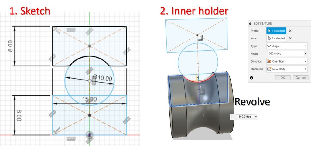
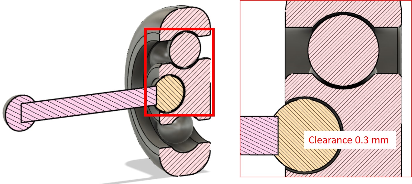
My design consists of 7 balls, inner ring and outer holder, inner holder has a hole, where the joint stick is inserted, allowing the rotation . I was curios if it is going to work. The parts of the initial sketch were Revolved. Then ball was created inside the construction, again, applying Revolve tool, balls we placed inside the bearing. Fillet tool was applyied to round the edges of the bearing. Ball joint in the middle was made by cutting the sphere in the middle, and then placing the shere inside the hole, with a clearance 0.3 mm.
At first I created the sketch from 2 rectangles and 1 circle intersecting both rectangles. The upper rectangle will be the outer ring, and the bottom one will become the inner ring.
Inner ring > Choose the bottom rectangular of the sketch > Create > Revolve > Choose the axis going through the center of the circle > OK
Outer ring > Choose the upper rectangular of the sketch > Create > Revolve > Choose the axis going through the center of the circle > OK
Ball > Create > Sphere > Set the center of the shere to the center of the sketched circle> the make 4 mm clearance between the rings and the ball, set the diameter of the sphere to 9.2, instead of 10 mm.
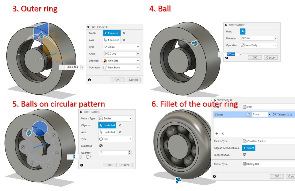
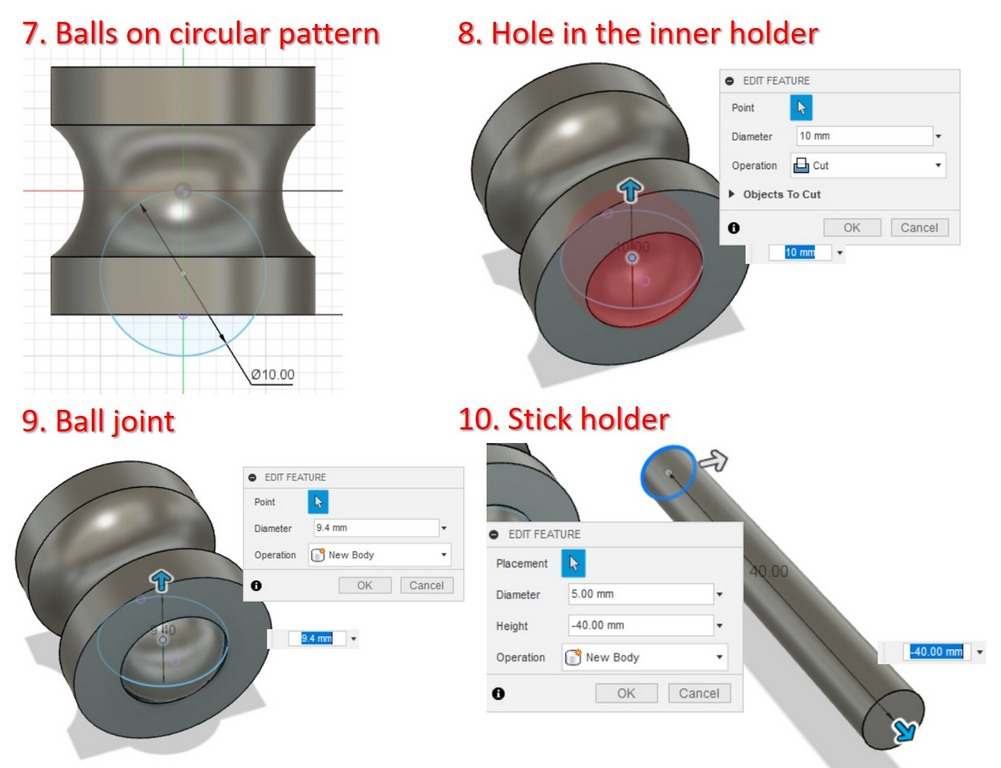
Making 7 balls > Create > Circular Pattern > Around the axis going through the center of the inner holder> the make 4 mm clearance between the rings and the ball, set the diameter of the sphere to 9.2, instead of 10 mm.
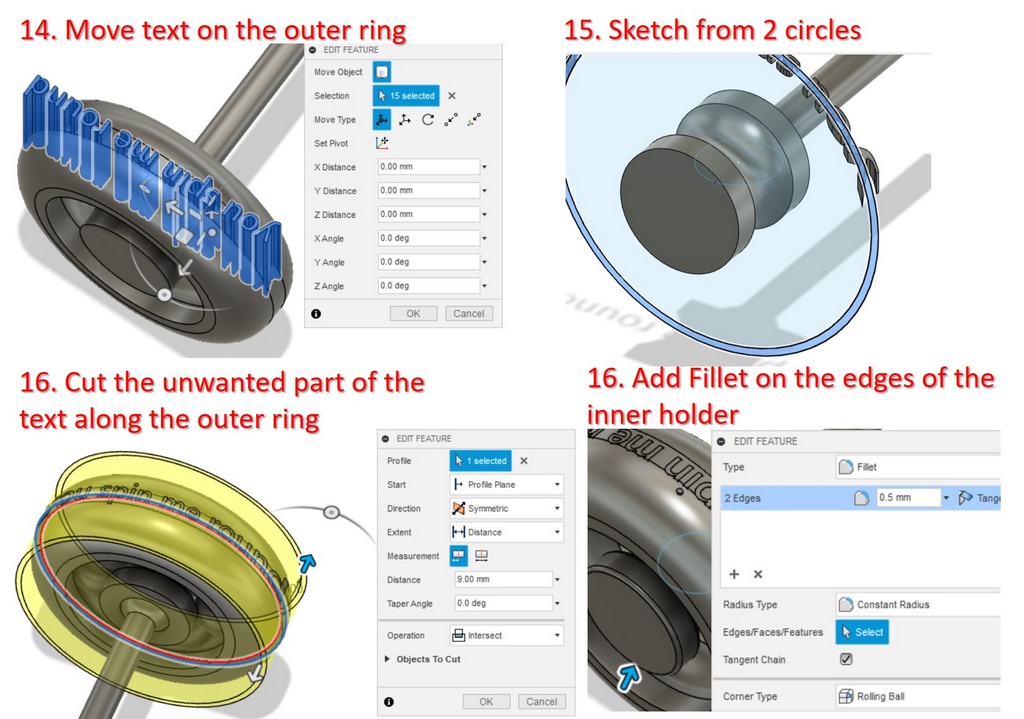
Fillet of the outer ring > Choose 2 outer edges > Modify > Fillet > 6 mm.
Hole for the Ball joint > Create the skecth 10 mm Circle, which fits well in the inner holder > Create > Shpere in the center of the inner holder (middle of the sketch) > Size: 10 mm > Operation Cut.
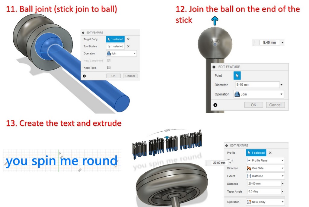
Ball joint > Create > Sphere (in the middle if the circle sketch for the hole) > 9.4 mm, in this way the clearance of 0.3 mm will be reserved around.
Stick holder > Create Cylinder > diameter 5 mm > Fillet > 6 mm.
Text was created as an Extrusion of the sketch. I just cut the excess of the figures with Intersection tool.
Fig 3. The steps to create the ball bearing in Fusion 360.
Fig 5. Model of ball bearing mechanism with ball joint holder made in Fusion 360
Fig 5. Section inspection and the clearance set in between the pin and the hole
I was eager to give one more try for additive manufacturing with a case designed for the board we made during week 4, but unfortunatly had no time. Anyway, I will try to print this out, and share the result later.
At first I designed the circuit board model with the corresponding dimensions, and then built the case around, leaving the space between the pins, joined together. The clearance was set to 0.3 mm. I relied on the size of our board, made the hole for 6 pins of the board in the lid.
I used Stratasys Fortus 380mc 3D printer, since it has provided satisfactory results in the testing for group assignment. Besides, this printer does not require continious supervising, therefore the printer can run on its own, which saves personal time.
The steps of 3D printing:
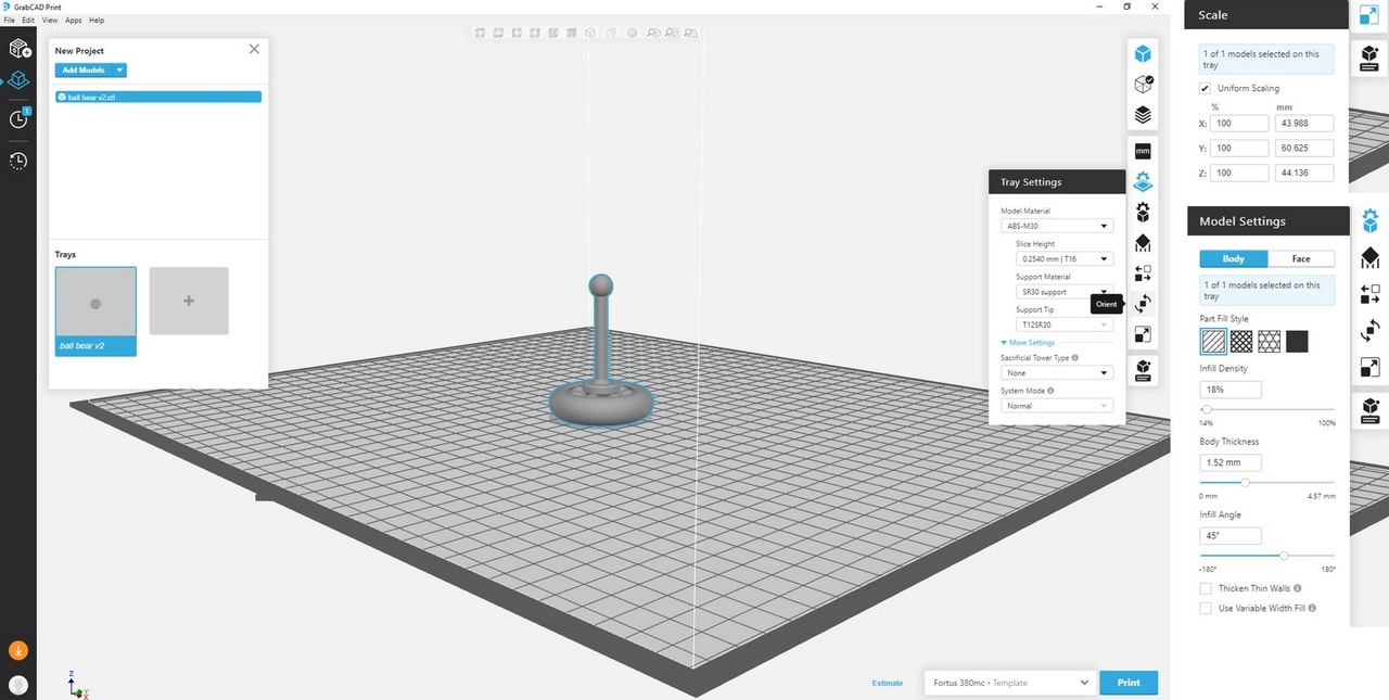
Import the STL model into GrabCAD Print software: File > New project > Add models > Choose the file.
Fig 8. STL model opened with GrabCAD Print
Tray settings: Shows the materials, in my case for printing the ABS-M30 is used with SR30 as a support. Unless you are going to change the materials, these setting are just informative.
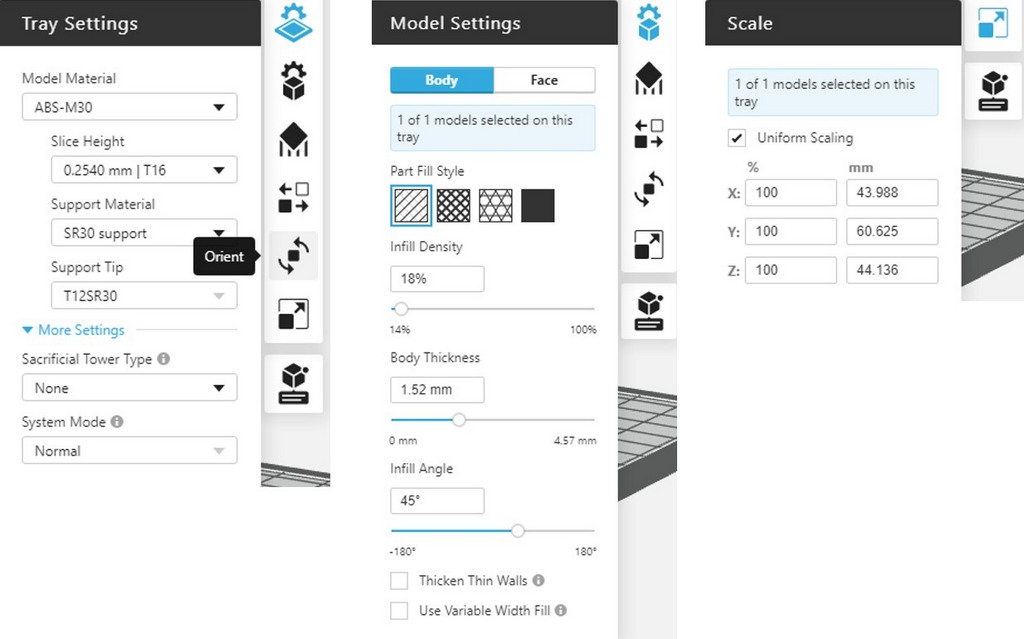
Model settings: I didn't change the default setttings > Part filling style, Infill density 18%, Body Thickness 1.52, and Infill Angle 45 °C.
Scale: Since I was satisfied with the object dimensions, I didn't change this setting.
Fig 9. The settings of the model in GrabCAD Print.
Support settings: Support style > SMART.
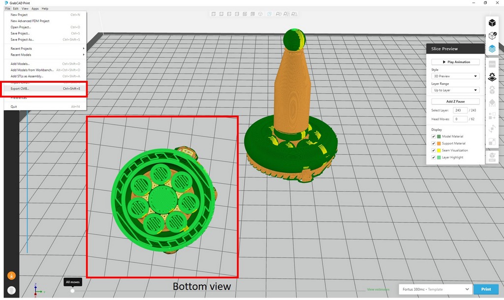
Slice Preview: GrabCAD Print software builds the support layers (orange) among the model material (green).
Export file: File > Export CMB by drag and drop or through File > Open.
Fig 10. GrabCAD Print software builds the support layers (orange) among the model material (green)
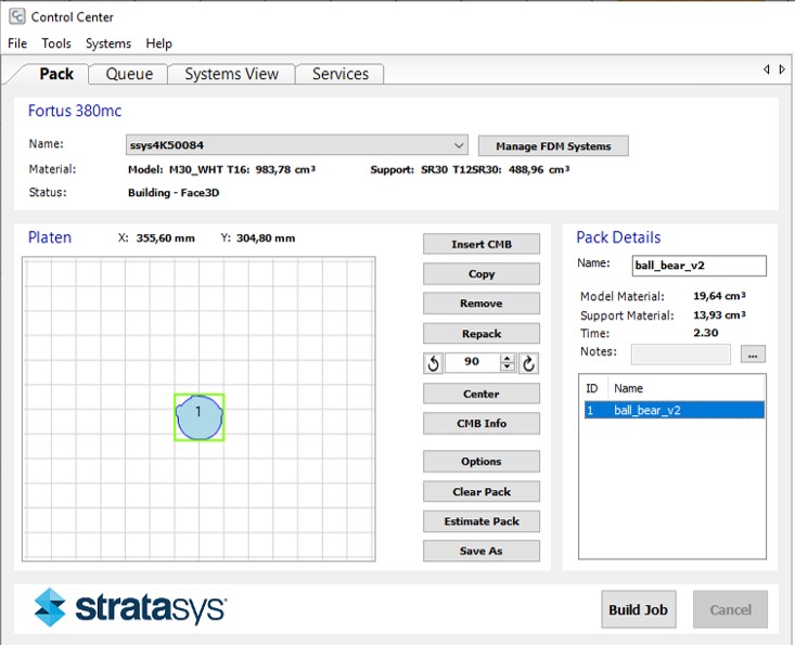
Control Center of Fortus 380mc: Import CMB file > Model location will appear on the Platen, one can arrange it in prefferebale way. If there are other objects in the printing process, choose the proper location. Repack automaticlly adjust the Part Placement in case few parts are going to be printed simultaneously. Pack detailes shows how much material and time are needed to print the model. (This also can be done through the Information touch screen panel of the printer).
Fig 10. Sending file to print. The origin of printing can be changed. Build job is sending file to the printer
Build Job will send the file to 3D printer.
Before sending file to print, be sure that the base sheet inside the printer is fixed well to be completely flat, also the sheet needs to be alighned with the special pins. Check if you didn't locate the model on the support poorly removed from the previous prints.
To fix the position of the base sheet wear the protection gloves, the machine could be hot from the previos jobs.
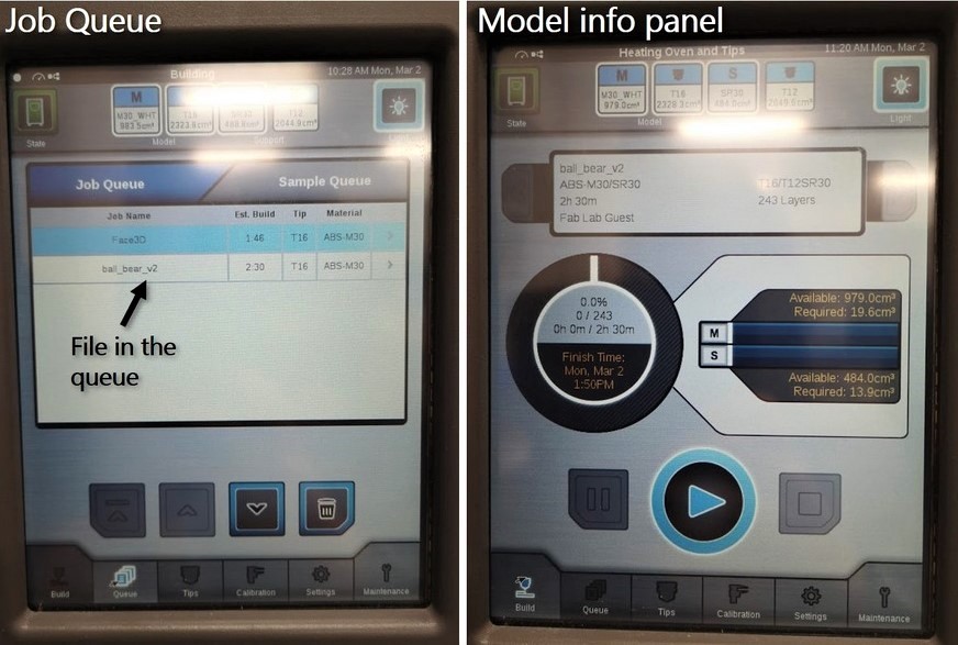
Information panel of Stratasys Fortus 380mc: printer has a touch screen panel showing the status of the machine, like the Job Queue, available materials, information about each model, such as materials and model printing time estimation. It shows that to print the ball bearing will take 2h 30m. Now, to start the job can be started by pressing Play middle button on the screen.
Fig 11. Information panel of Stratasys Fortus 380mc
When the model printing is finished, it can be removed from the printer. Wearing protective gloves, the base sheet is taked from the printer. Then, using the metal spatula I very carefully, trying do not damaged the sheet and the model, detached my model from the sheet.
To remove the support surrounding the object, it should be placed into the tank of Sodium Hydroxide (NaOH), which dissolves the support material. NaOH is a caustic alkali, it is necessary to use the gloves!. My ball bearing was ready after approximately 24 hours.
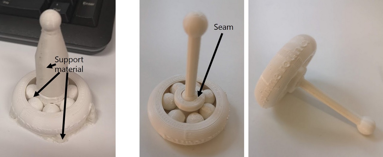
Fig 12. 3D printed model right after the printing, and after removing the support material during 24 hours in sodium hydroxide bath
The size of the model was quite small, so the resoluton of the print was not enough for the fine font printing of the text. Seams are visible, they don't make a problem for the inner shperes, as there is enough gap between them. However, the ball joint got stuck inside the inner holder, as the seams appeared at the same spot for the inner ball joint and surrounding material of the inner holder. In attempt to rotate the joint, the stick bravely broke. The rest seem to work though.
UPDATE.
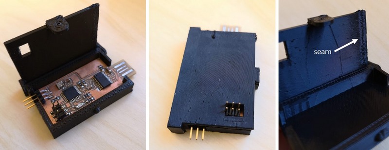
I've printed the case for the board, the lid was printed vertically, therefore surface wasn't smooth enough. By placing it horizontally I would get better result. However it works fine, and board suits inside the case.
Fig 13. 3D printed case for the circuit board.
3D scanning
Sense 3D scanner
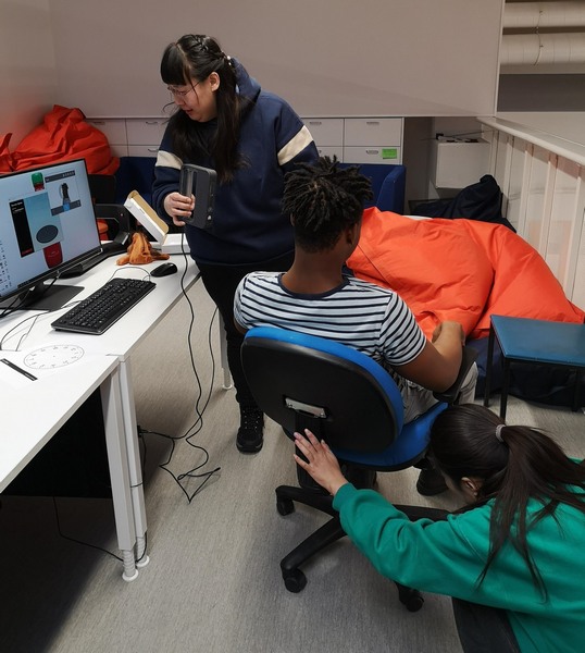
At first, we made few attempts to scan each other with the Sense 3D scanner . This was kind of challenging, because to get the good 3D scan, scanning should be made as precise as possible. We began to move around the person, who is scaned, but there were 2 problems. First one, that it was hard to hold the scan stadily, while moving, and the second one, the scanner was connected to the computer with USB cabel, which was limiting the distance. We found a better way - to rotate the chair with the person being scaned, while the person making the scan is staying stadily. In this way we managed to get better, but still not the perfect results.
Fig 14. Innovative Scanning process with Sense 3D scanner 3D scanner.
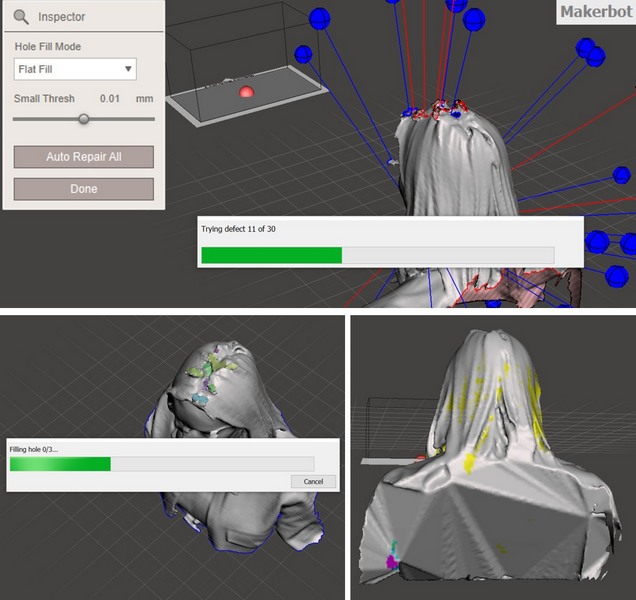
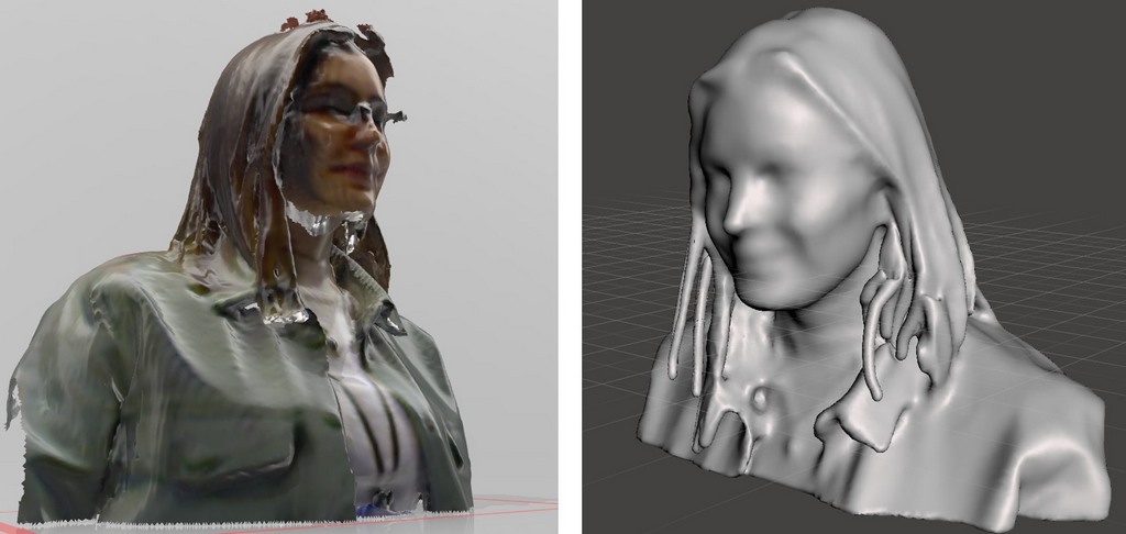
After scanning was finished, I saved the scan in OBJ format. As it can be seen, the quality is not perfect - some zones, at the top and bottom, were not scanned properly, which is resulting in the holes. I tried to fix the scan with Autodesk Meshmixer:
UPLOAD > I just dragged the file into the Autodesk Meshmixer window, and in was uploaded.
FILLING THE HOLES > The holes of the scan are highlighted with blue. To fix the holes in the model mesh > Analysis > Inspector > Falt fill > Auto Repair All.
Fig 15. Filling the holes of the model in Autodesk Meshmixer.
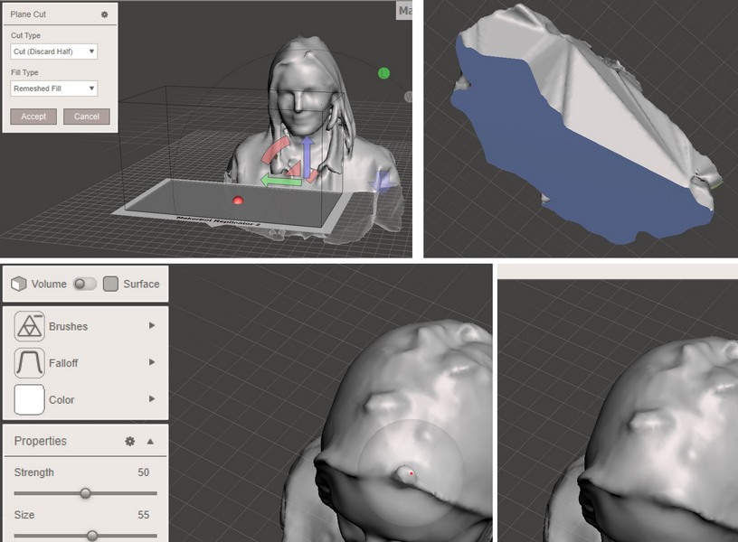
PLANE CUT > To remove uneven lower part > Edit > Plane Cut > Set the plane > Cut type: Discard Half > Filled type > Remeshed Fill.
BRUSH > To smooth the bumps on the mesh > Sculpt > Brush > Flatten. Another option could be Sculpt > Fallof > Flat. To extrude the mesh Sculpt > Brush > Drag (I made this "Ktulhu style" hair).
Fig 16. Cutting the plane and using the brushes to fix the model in Autodesk Meshmixer.
Fig 17. The scan obtained with Sense 3D scanner and after modifications made in Autodesk Meshmixer. Finally, my fans can download and 3D print the creepy model of me, yeay!... :).
Before uploading the model on my page I had to reduce the mesh to make the file size of the model smaller, for that in the Autodesk Meshmixer: Select > Modify > Select All > Edit > Reduce > Accept, then File > Export
MakerBot Digitizer
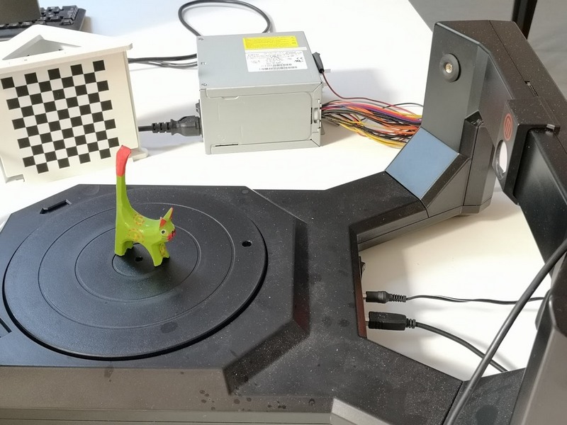
The next scanner I tried was a MakerBot Digitizer . This is a type of the desktop scanner, where the object is placed on the automatically rotating stage and scanned with a red light beam, which is reflected from the object surface to the camera, allowing to map the surface. Scanner also has very user friendly software, so no exta knowledge are needed to make a scan. The only limitation is the size of the scanned object, which should not exceed about 20x20 cm.
Fig 18. MakerBot Digitizer 3D scanner and the Cat figure to be scanned.
Steps to make the scan:
If the scanner wasn't calibrated, make the calibration using the checkerboard pattern, which helps the scanner to adjust to the room lightning.
Light conditions can be also chosen in the software (Bright, Medium or Dark). Too much light will result in high reflectance from the object, while the darkness also makes it hard to scan.
The object is placed in the center of the scanner stage.
Check the distance from the surrounding objects, which may appear in the field of view of the scanner and interfere the scanning process, appearing as a part of the scanned object.
Scan through the MakerBot Digitizer Software by following the steps and choosing from the options, such as light conditions, and then press Scan.
The object is placed in the center of the scanner stage.
Multiscan > if the model's parts were not scaned properly, software will synthesize multiple scans of the object in one model.
The object can be resized, moved and viewed from different perspectives, as well as previewed for 3D print in MakerBot Digitizer Software.
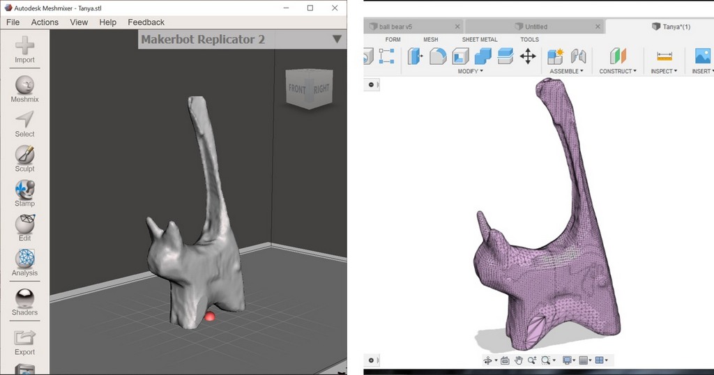
I saved my scan in the OBJ format and opened it in Fusion 360. The model appears as a mesh object.
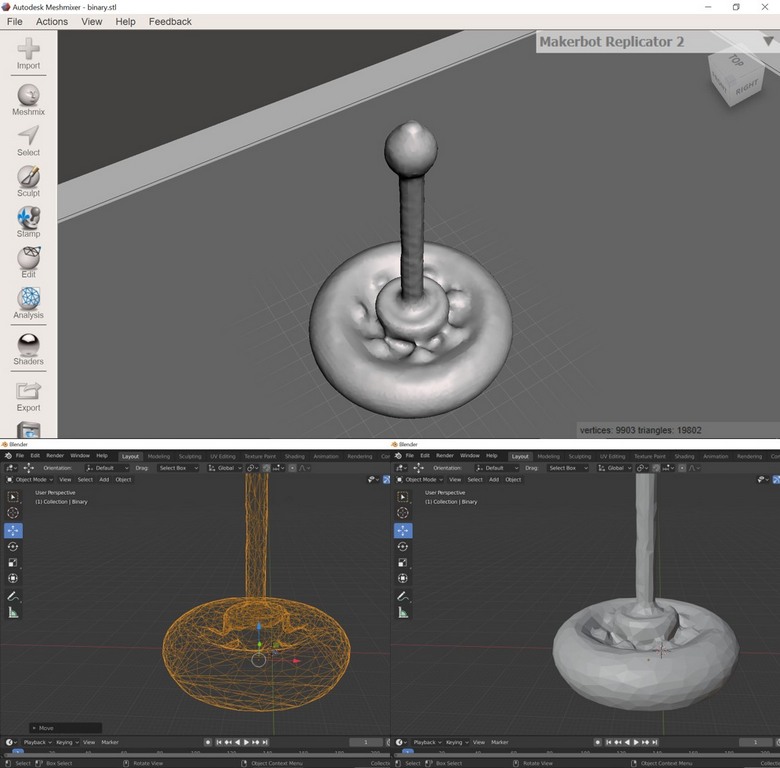
Out of curiosity I also scaned 3D printed ball bearing. The quality of the result came really good, I opened the file in Blender, where the mesh properties can be easily modifed.
Fig 19. MakerBot Digitizer 3D scanning result and importing the scan in to Fusion 360
Fig 20. MakerBot Digitizer 3D scanning result of the 3D printed ball bearing opened in Autodesk Meshmixer and the same file imported in the Blender software with a modifier : Add modifier > Decimate.
The hardest part this week for me was choosing the design for printing and dealing with big size files. It turned out that accidently I was trying to push a big file and was receiving the message fatal: pack exceeds maximum allowed size. Ivan helped me resolved it, the steps are:
find the offending file: git ls-tree -lr Commit SHA
git rebase -i Commit SHA~1
mark as editable the Commit SHA in the rebase file