Task 11
Input devices
In this week, I was given a task to have a group assignment and an individual assignment. The group assignment was to probe an input device's analog levels and digital signals, and the individual assignment was to measure something: add a sensor to a microcontroller board that you have designed and read it
Group Task
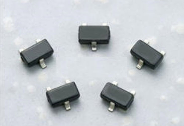
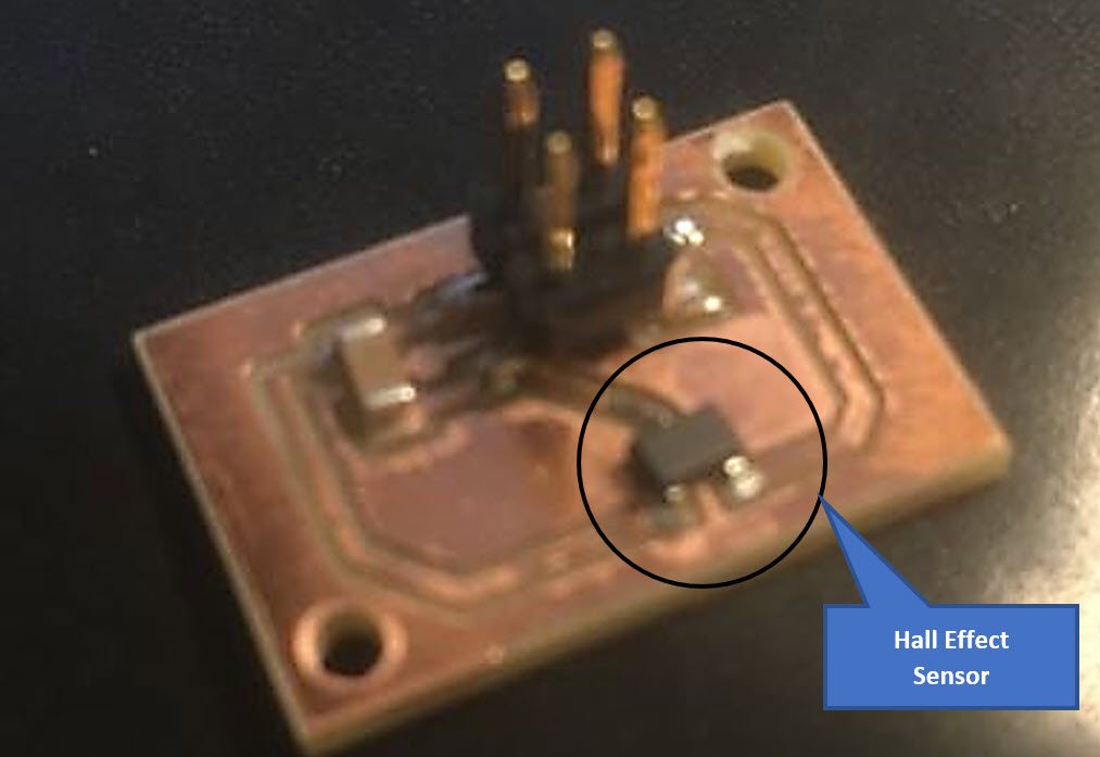
For the group work, I worked with Alok and Micheal to probe the hall sensor’s analog outputs with the change in the magnetic field. A Hall effect sensor is a device that is used to measure the magnitude of a magnetic field. Its output voltage is directly proportional to the magnetic field strength through it. Hall Effect sensors are used for proximity sensing, positioning, speed detection, and current sensing applications. The Hall Effect sensor that we used was A3245: Chopper-Stabilized Omnipolar Hall-Effect Switch. The A3245 integrated circuit is an omnipolar, ultrasensitive Hall-effect switch with a digital output. This device has an integrated regulator permitting operation to 24 V, making it the first omnipolar switch available for operation to 24 V. This device is especially suited for operation over extended temperature ranges, up to +150°C.
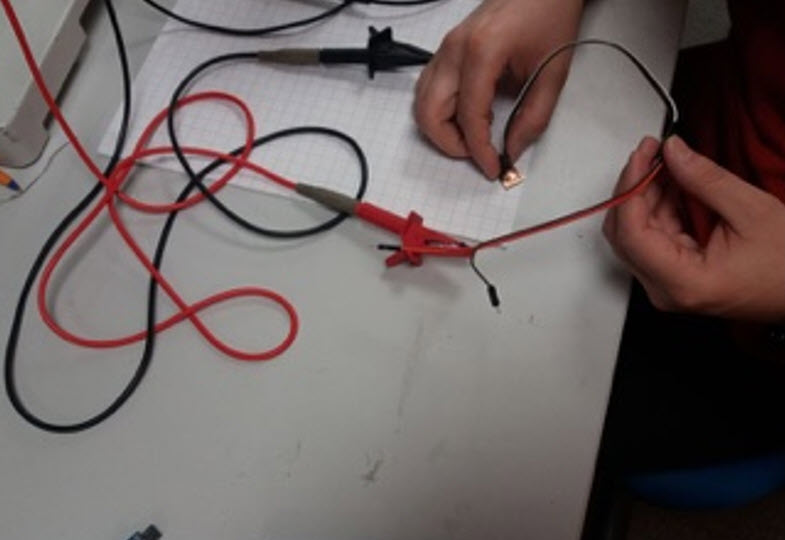
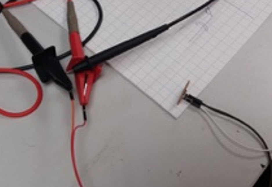
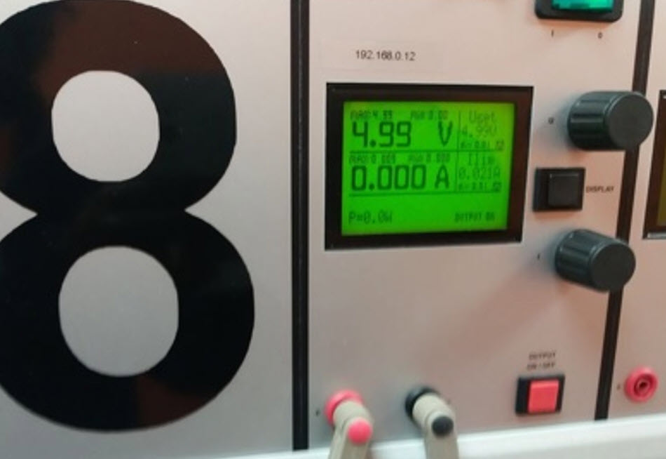
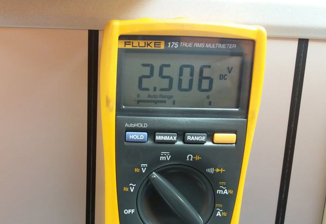
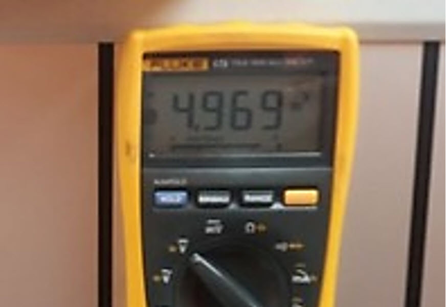
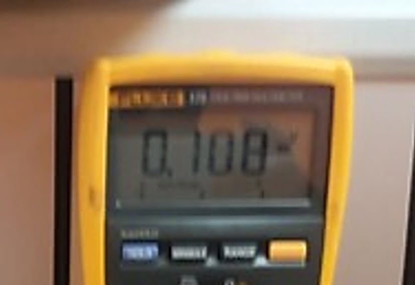
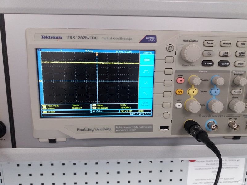
The sensor board was tested by applying 5V power supply across it and measured the resulting voltage at the output of the sensor. The output voltage with no magnetic field nearby was 2.5V. When the north pole of the Magnet was brought close to the sensor, it gave an output voltage of 5V and when the south pole of the magnet was brought close to the sensor, it gave an output voltage of 0V, This clearly Indicated that the sensoe was working perfectly.
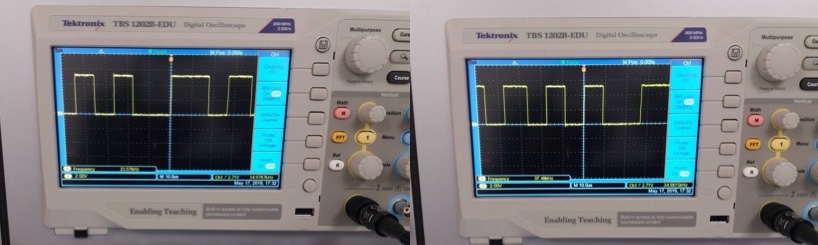
We also measured the digital signal with an oscilloscope by attaching the ground pin to the PCB ground and the positive probe to the transmit/receive pins of the ATtiny44. When the the flip side of the magnet came close to the sensor, we got following signal from oscilloscope.
When the magnet was close to the sensor, we got the following signals.
Therefore to conculde, we have a clear idea about Digital to Analog Conversion
Inidividual Task
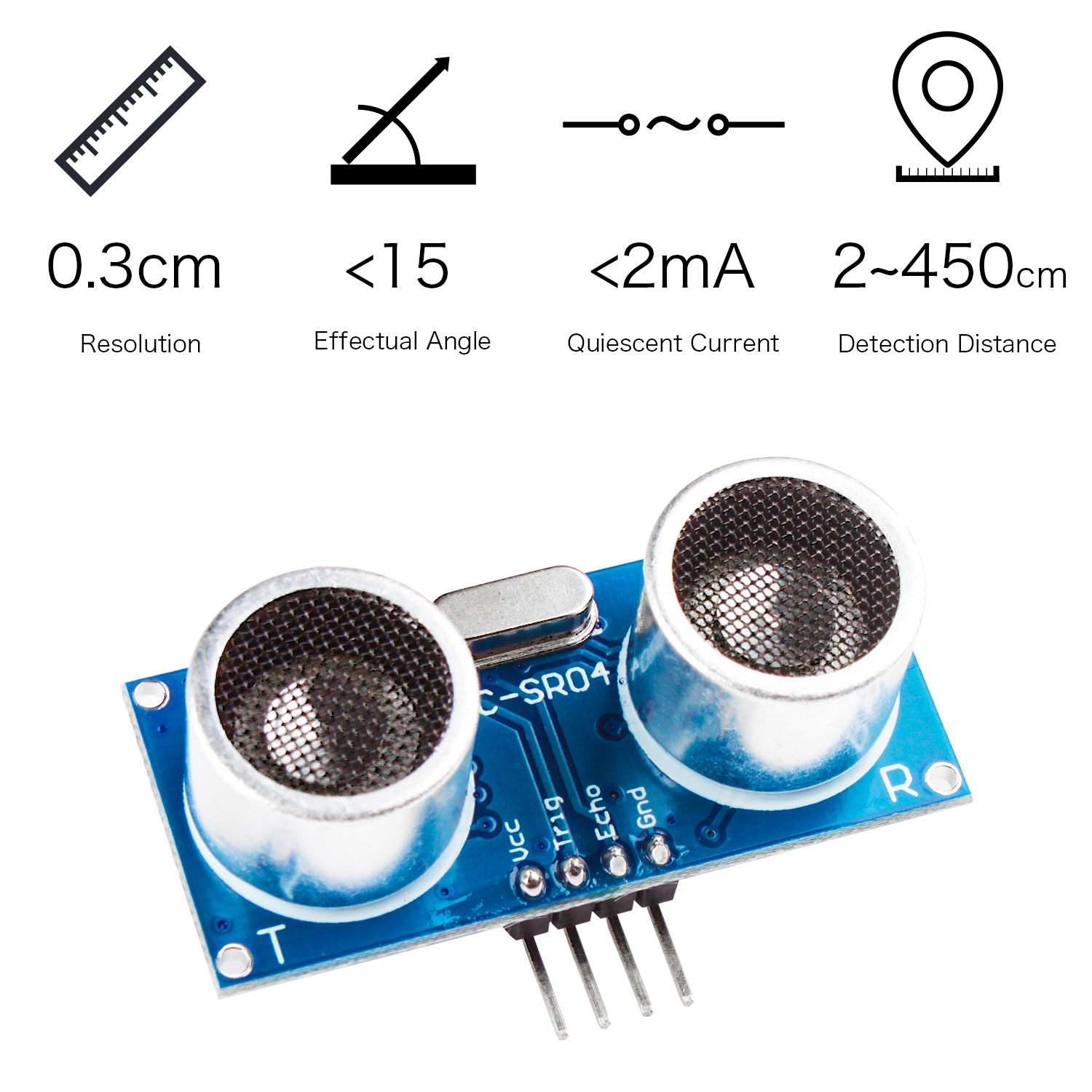
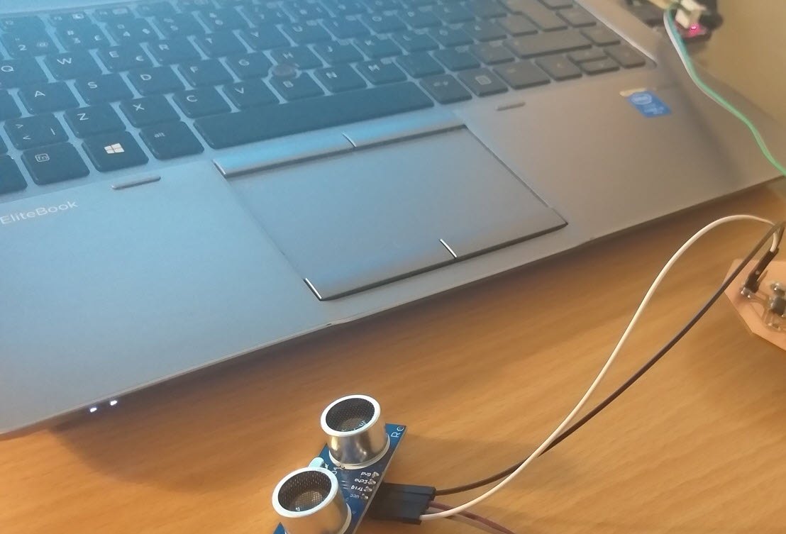
This week assignment, I tried to work with the Ultrasonic ranging Module, which I was planning to use in my Final Project. Ultrasonic ranging module HC - SR04 provides 2cm - 450cm non-contact measurement function, the ranging accuracy can reach to 3mm. The modules includes ultrasonic transmitters, receiver and control circuit.
- The basic Principle of work for HC - SR04:
- Using IO trigger for at least 10us high level signal.
- The HC-SR04 Ultrasonic distance sensor consists of two ultrasonic transducers. The one acts as a transmitter which converts electrical signal into 40 KHz ultrasonic sound pulses.
- The receiver listens for the transmitted pulses. If it receives them it produces an output pulse whose width can be used to determine the distance the pulse travelled.
- Wires connecting direct as follows for HC - SR04:
- 5V Supply.
- Trigger Pulse Input.
- Echo Pulse Output.
- 0V Ground
Board design and fabrication
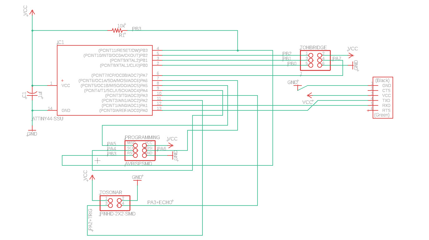
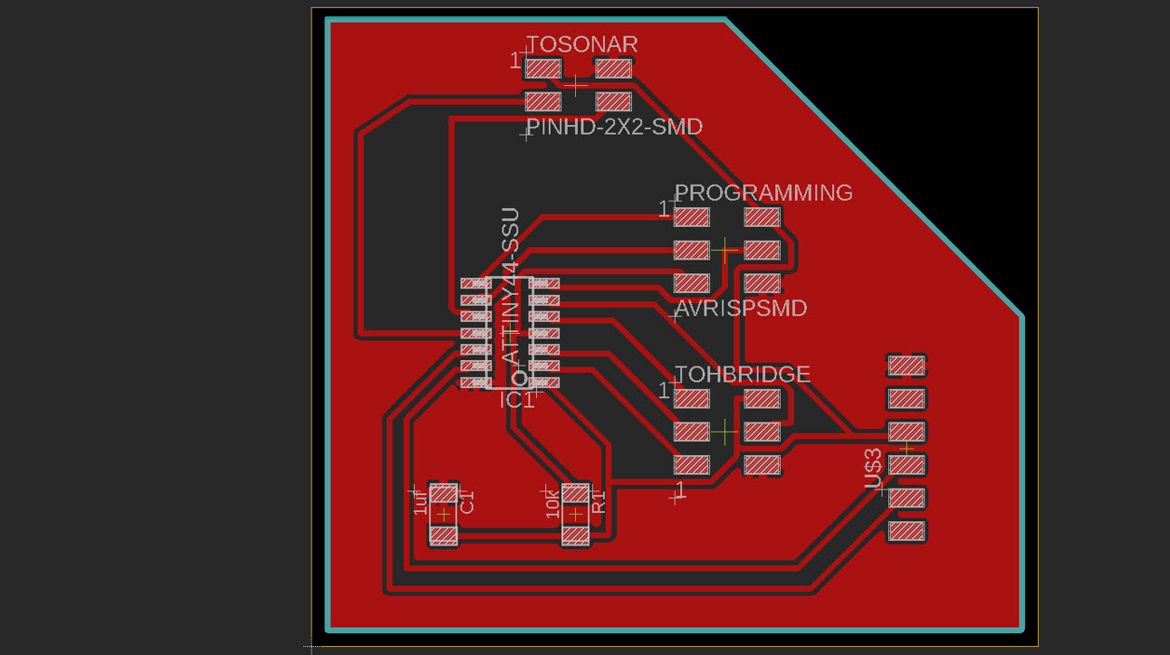
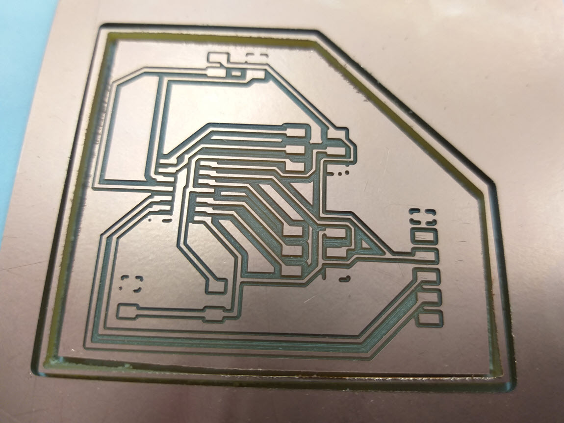
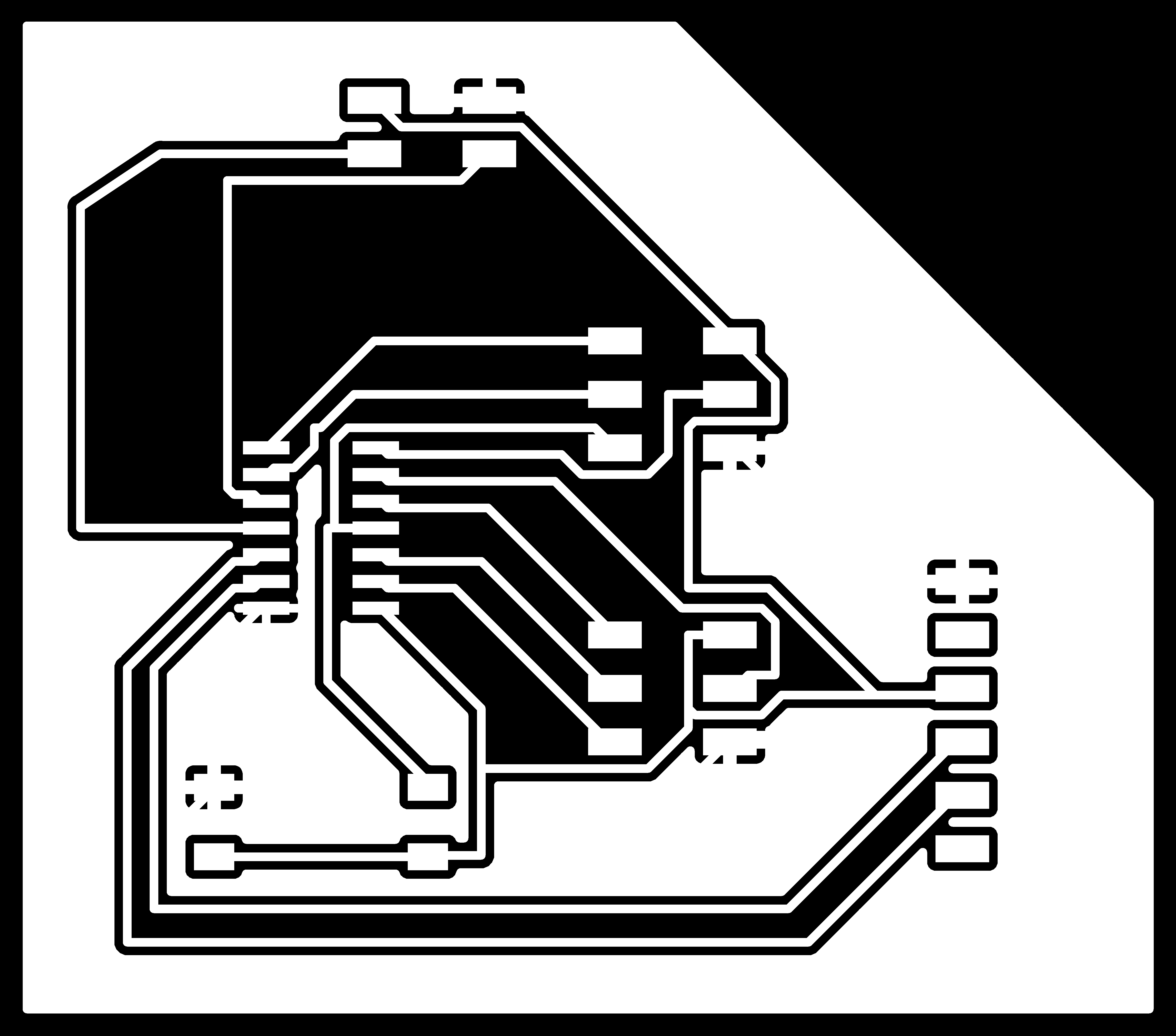
I designed a new schematic for my input device board using Attiny 44A with multiple 2x3 pin header. For this purpose, I followed the previous Week 07 assignment to follow the design rules and guidelines. The main goal of the board was to have an extra 3x2 pin header that I was planning to use it in my Final Project by Interfacing the H Bridge and Ultrasonic sensor with Attiny to control the motion of the motors with respect to distance. I gave the name "To Sonar", "H-Bridge" and "Programming" to the headers to differentiate them. At this point of time, the plan was to reuse the board for final project thereby I planned, designed accordingly and gave the names to the pin Headers. The Board schematic is given in the figure below
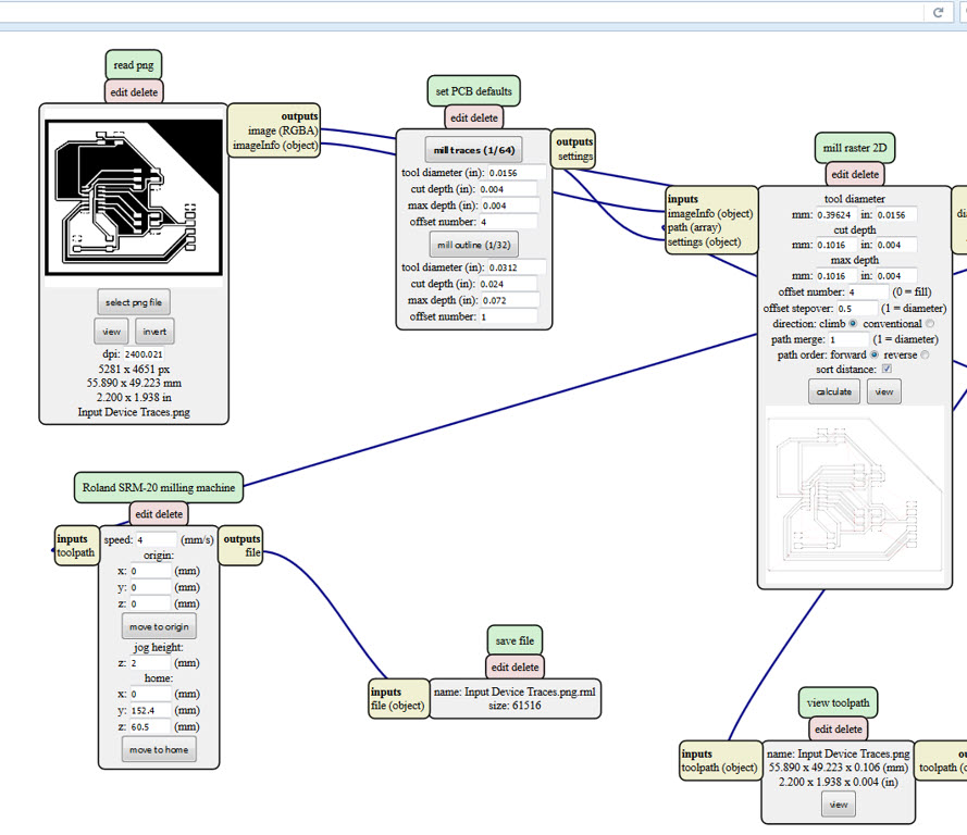
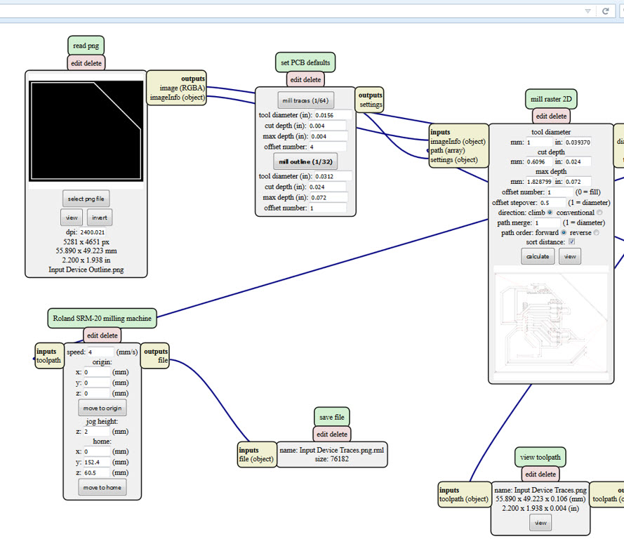
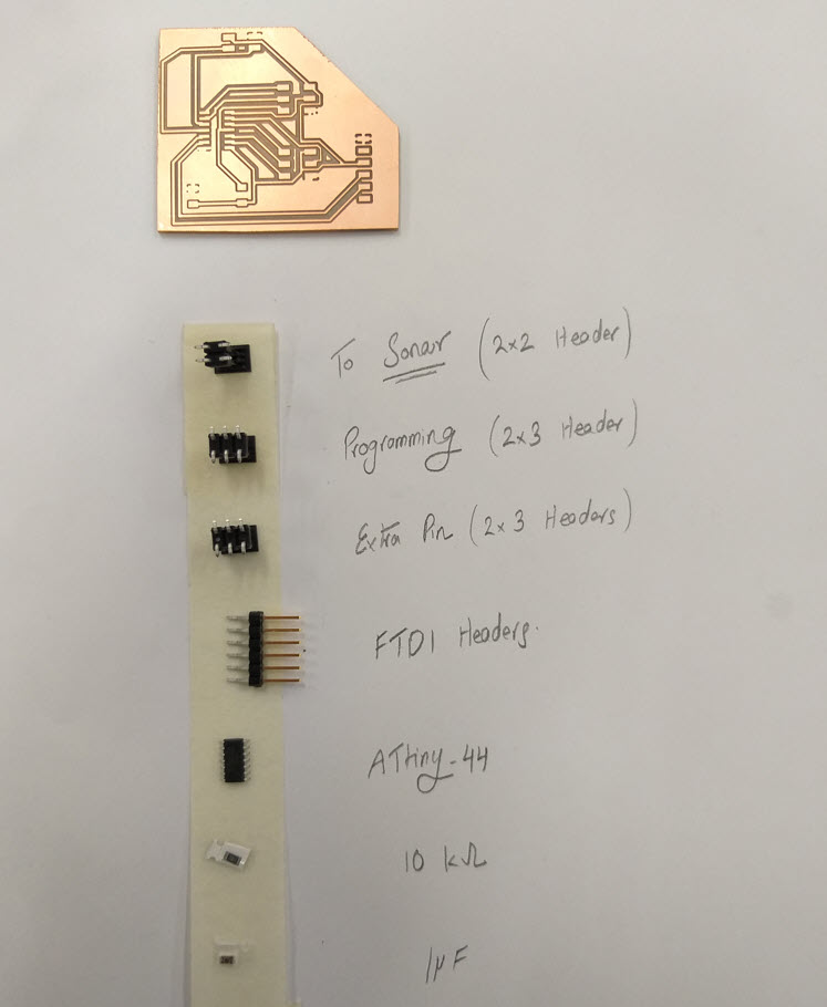
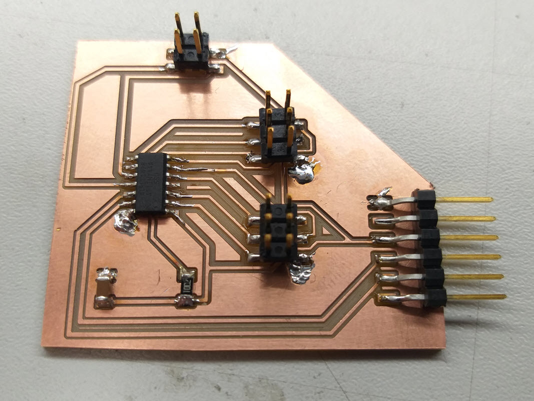
For milling and soldering, I referred to my previous assignment of Week 05 assignment and Week 07 documentation. Below figure shows the final milled and soldered board with all the components in the schematic.
Programming the Board
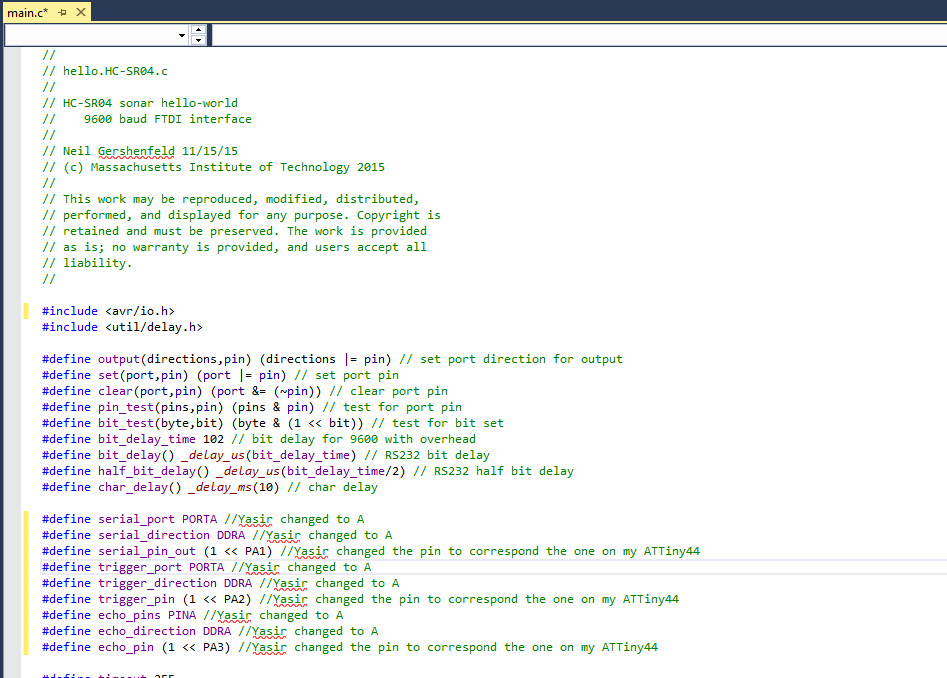
To Program the board, I connected my Programmer to the Sonar Board via the AVRISP headers and connected it to my computer using the FTDI. I used Neils hello world hello.HC-SR501.c and also I referred to Heidi's page as a reference to peform the coding. Since I used Attiny 44A. I modified the code according to the pins that I was utlizing. I did the required changes and commented the code
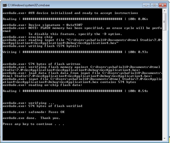
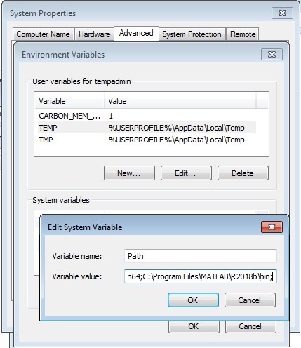
The code was successfully written in the board, the AVRdude was successful in uploading the program to the board, the next step was to visualize the data. For this purpose I decided to use Neils hello.HC-SR04.py. Since the code is in python and to open it, I had to Install Python 2.7.14, which I downloaded and Installed. After Installing, we need to add the location of the Install Python into our Environmental variables as well.
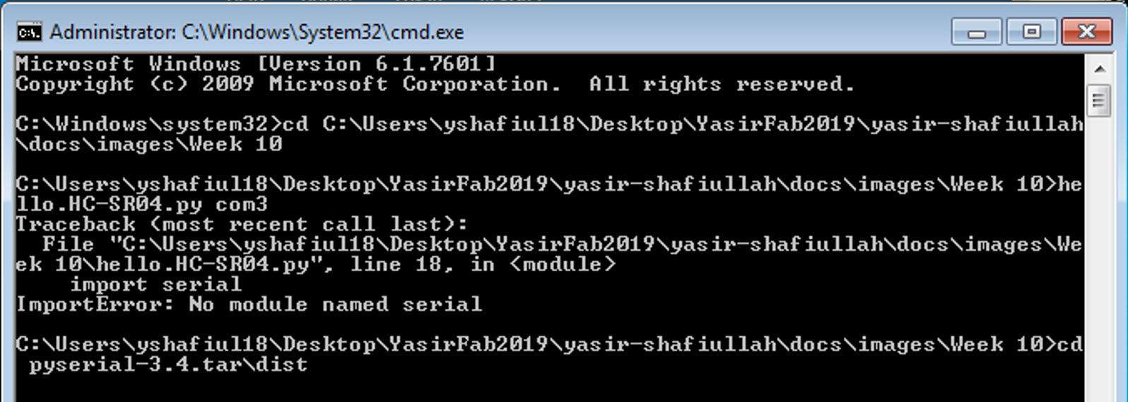
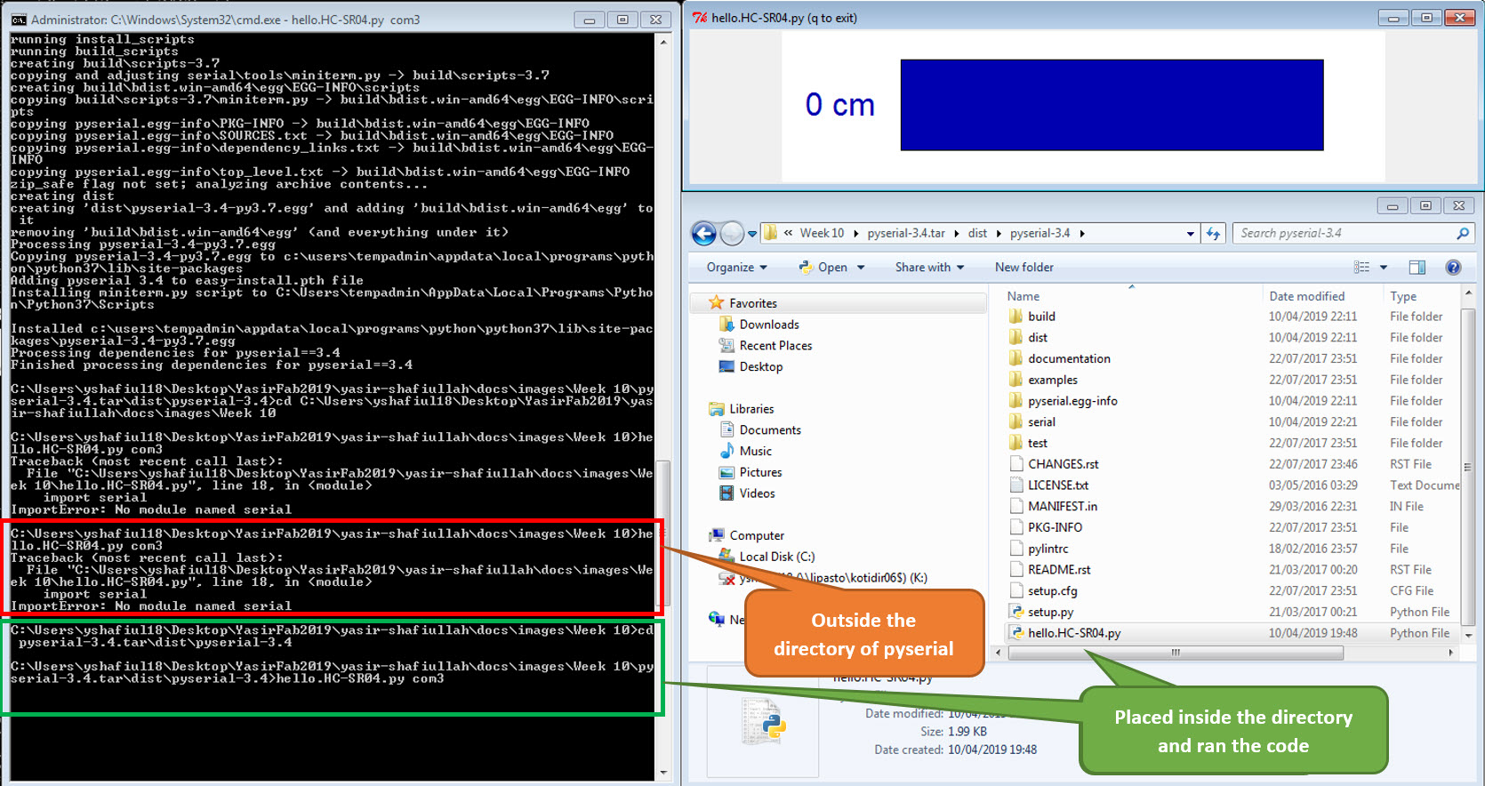
To open the python code, the command prompt of windows is opened and from there I tried to open the Neils hello.HC-SR04.py, unfortunely I was encountered an Import Error namely "No module named serial".
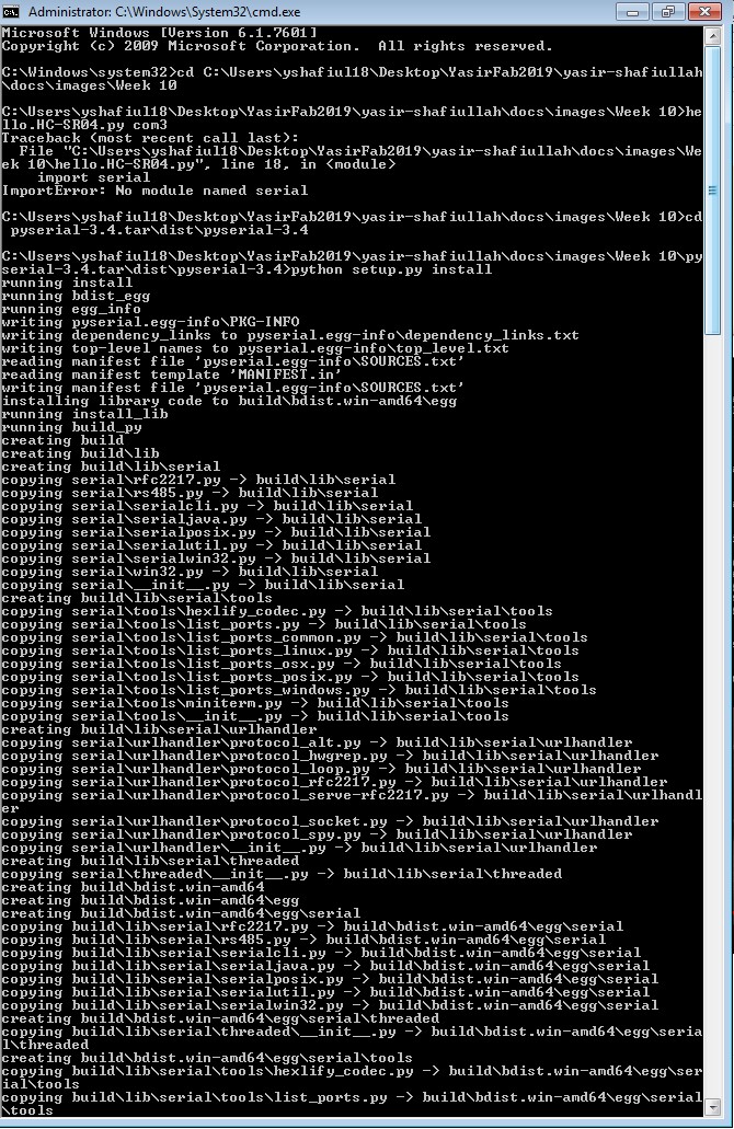
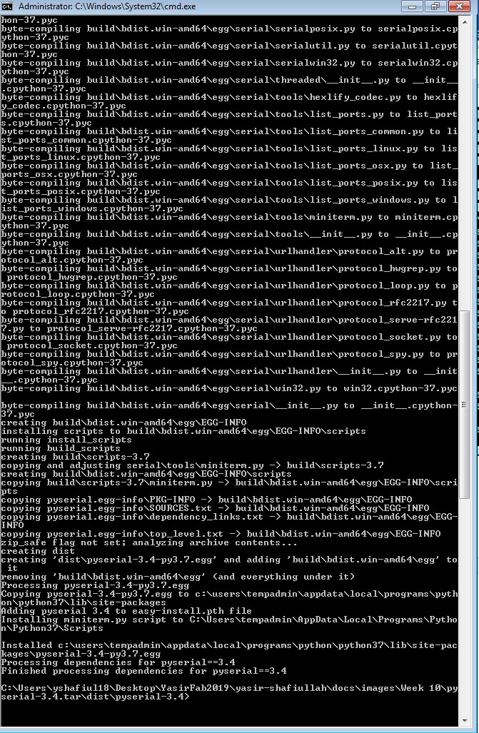
I looked back at Heidi's page and she was also encountering the similiar error. She recommended to install python serial. After bit of googling, I was able to find a youtube link which describe how to install python serial with another link to download the files. I downloaded the files. I followed the Instructions and opened the Command prompt window in Admistrator mode and then I installed the python serial as seen below
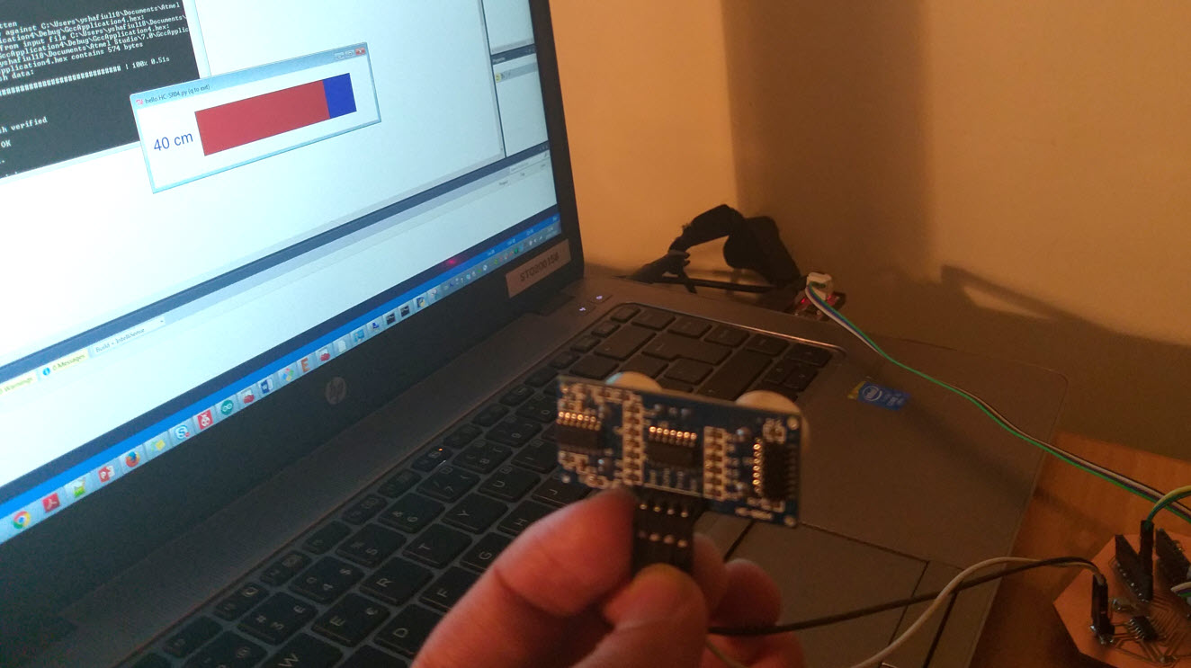
After that, I tried to run the Neil's hello.HC-SR04.py code and it again gave me the Import Error namely "No module named serial". I tried to written the code again in Attiny 44A but it was all in vain, there was no proper sign of anything working at this moment. I tried googling it and I came to know that inorder for the .py file to open I have to place the file inside the python serial directory, thereby I placed the code inside the directory and ran it again and finally it opened giving me 0cm distance (Since I didn't connected the Sonar Board till now).
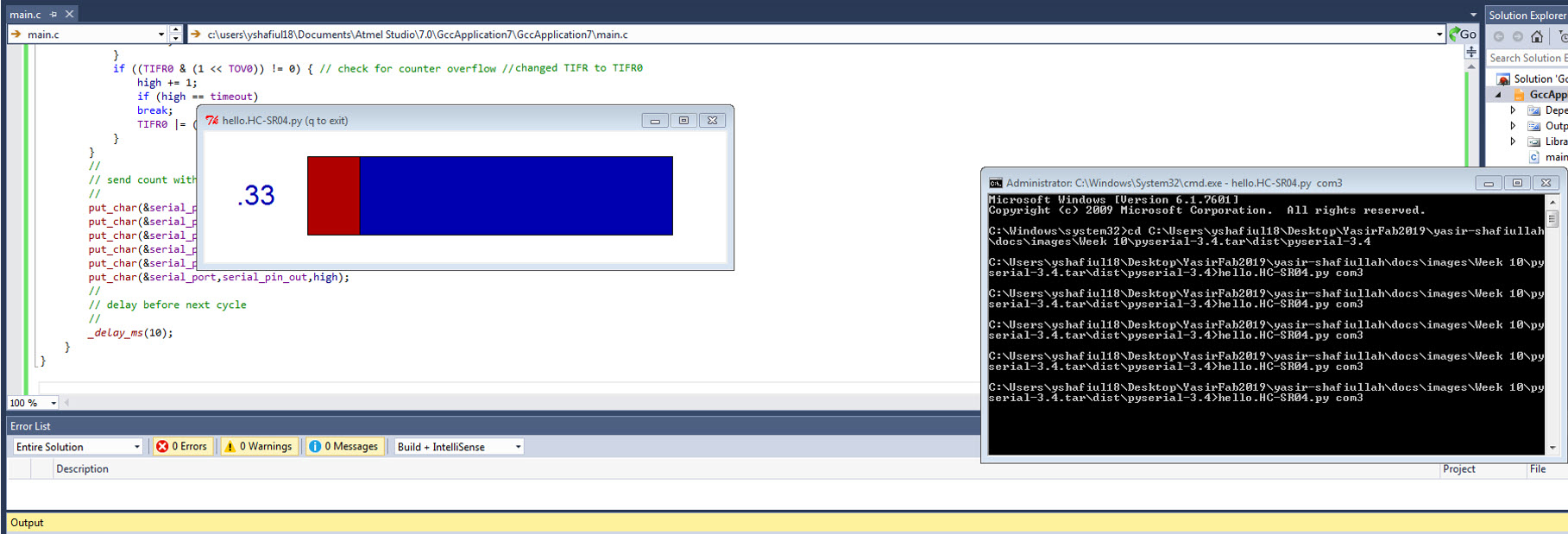
Now I connected the Sonar Board and run the hello.HC-SR04.py again but this time, it was measuring nothing even by changing com ports. The value was fixed at 0.33 whatsoever and there was no movement at all and went into not responding.
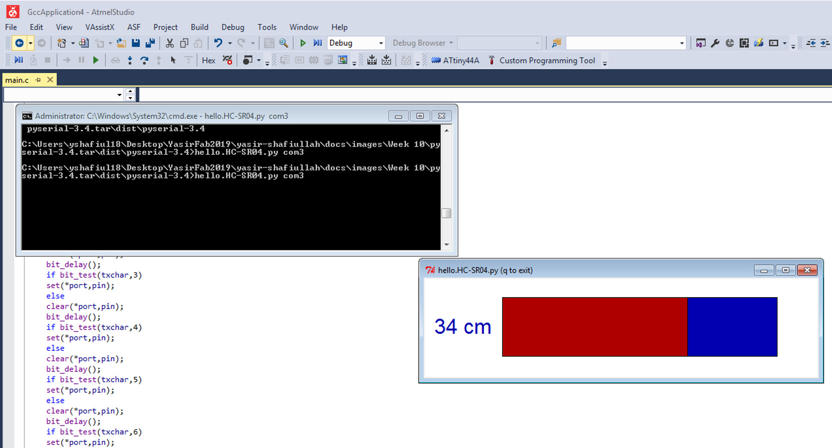
I asked one of my Instructors Ari and he asked me to define the clock in the code since my circuitory only uses the Internal clock thereby I put the clock frequency to 8Mhz (8000000UL). The details about the internal clock were found on on the datasheet. Here the datasheet was helpful for me to program the board. Heidi was also facing the similiar issue and on her page she recommended to change the clock frequency from 20Mhz (20000000UL) to 8Mhz (8000000UL) since the ultrasonic sensor uses the Internal clock for computations and it worked finally. The Sonar is measuring distance and its working fine.
Resources Utilized
- I utilized these resources for this task:
- Atmel Studio 7
- Python 2.7.14