Week 9. Embedded Programming
Go to:
1. Group work
Task: Compare the performance and development workflows for other architectures.
Group:
This week we worked all together on the group assignment.
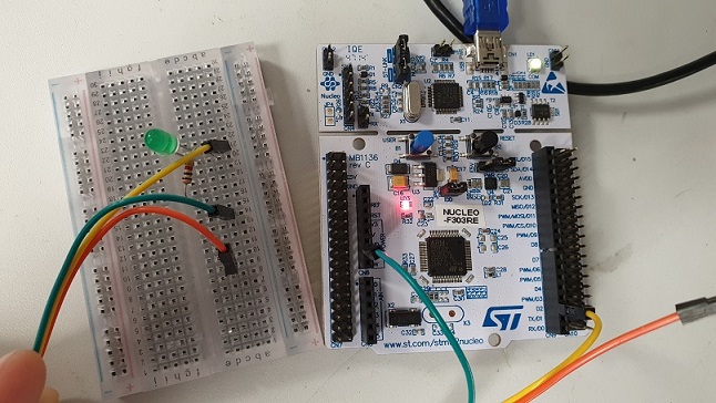
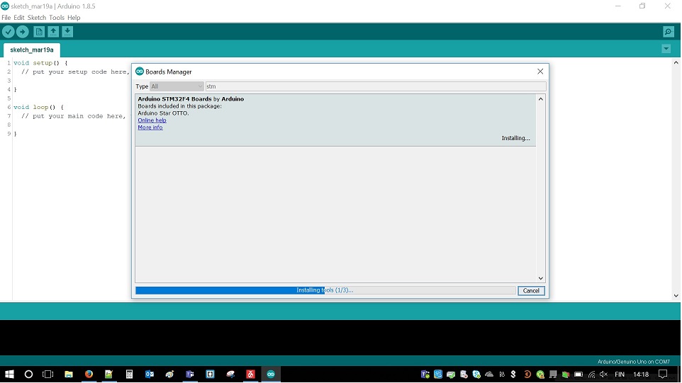
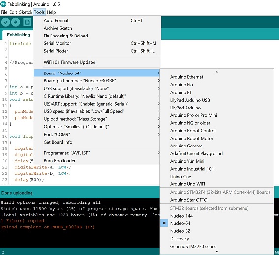
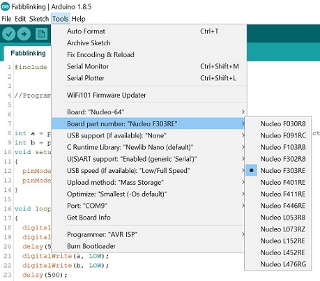
We tested STM32 Nucleo-64 development board with STM32F303RE (72MHz) MCU and ESP32 board using Arduino IDE. Datasheet
Datasheet for STM32F401RE MCU (84MHz) just to compare...
We tested the STM32 Nucleo-64 development board with STM32F401RE MCU and ESP32 LOLIN32 development board using Arduino IDE. ST32 is a family of 32-bit microcontroller integrated circuits by STMicroelectronics. This group is related to same 32 bit ARM processor. The STM32 F4-series is the first group of STM32 microcontrollers based on the ARM Cortex-M4F core. The F4-series is also the first STM32 series to have DSP and floating point instructions. The F4 is pin-to-pin compatible with the STM32 F2-series and adds higher clock speed, 64 KB CCM static RAM, full duplex, improved real-time clock, and faster ADCs. All devices offer one 12-bit ADC, a low-power RTC, six general-purpose 16-bit timers including one PWM timer for motor control, two general-purpose 32-bit timers. They also feature standard and advanced communication interfaces.
- Up to three I2Cs
- Up to four SPIs
- Two full duplex I2Ss. To achieve audio class accuracy, the I2S peripherals can be clocked via a dedicated internal audio PLL or via an external clock to allow synchronization.
- Three USARTs
- SDIO interface
- USB 2.0 OTG full speed interface
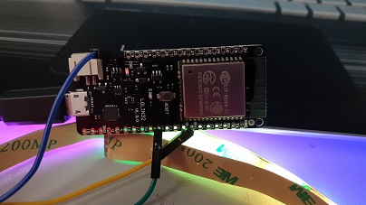
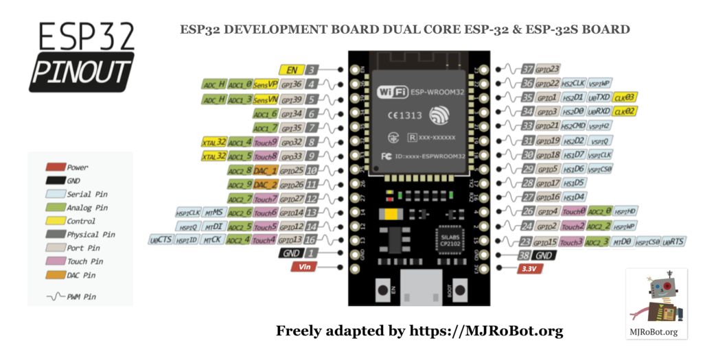
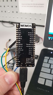
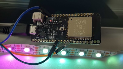
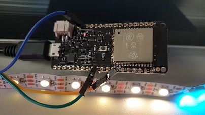
ESP32 is a series of low-cost, low-power system on a chip microcontrollers with integrated Wi-Fi and dual-mode Bluetooth. The ESP32 series employs a Tensilica Xtensa LX6 microprocessor in both dual-core and single-core variations and includes in-built antenna switches, RF balun, power amplifier, low-noise receive amplifier, filters, and power-management modules. ESP32 is created and developed by Espressif Systems, a Shanghai-based Chinese company, and is manufactured by TSMC using their 40 nm process. See the more details about ESP32 LOLIN32.
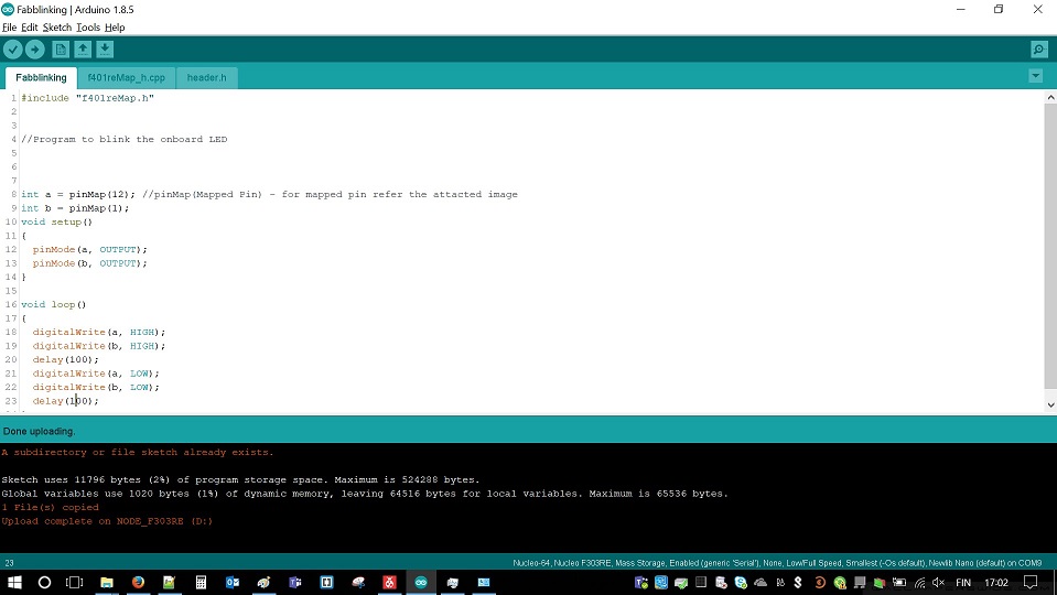
We walked through the very same steps for ESP32 and made some LEDs fading. From pin map we took pin numbers and connected the LED stripe to the board.
In a matter of comparing performance this page helps a lot. Here you can compare performance and price of different boards.
2. Datasheet
Task: Read a microcontroller data sheet.
Outstanding reading! 238 pages of pure joy. A Song of Ice and Fire or Lord of the Rings are not even close to this piece of art. But don't be so scared, it has a shorter version(22 pages). So (no more jokes, I promise), what do you need to know about ATtiny?
ATtiny24A/44A/84A is a low-power CMOS 8-bit microcontroller based on the AVR enhanced RISC architecture. By executing powerful in structions in a single clock cycle, the ATtiny24A/44A/84A achieves throughputs up to 1 MIPS per MHz allowing the system designer to optimize power consumption versus processing speed.
It has a lot of features. But the main are:
- High Performance
- Low Power Consumption (Active mode 210 µA at 1.8V and 1 MHz)
- 4K Bytes of in-System Flash program Memory
- Operating Voltage: 1.8-2.5V
- Universal Serial Interface
- Cost less than 1$ per piece
USI – Universal Serial Interface (p.117-128) was the most interesting part. Reading it gave me some understanding of Neil's echo.c code. But I was focusing on how I can operate LED stripe using ATtiny44. From the internet, mostly, I've found out, that it can run about 20 LEDs. In my final project I will use about 270 of them. This is a thing to consider: use several ATtinys or switch to ATmega?
Anyway, I did my reading. Now I know where I can find an answer to the problems I probably will face soon. If you still have question about ATtiny, 238 pages of the manual are waiting for you.
3. Programming
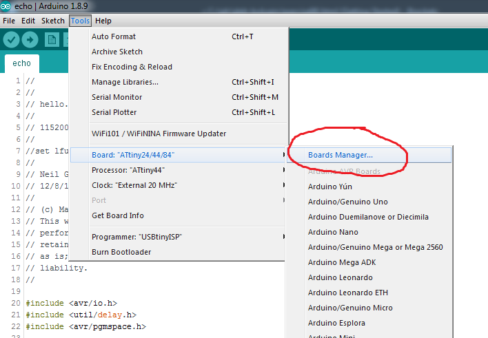
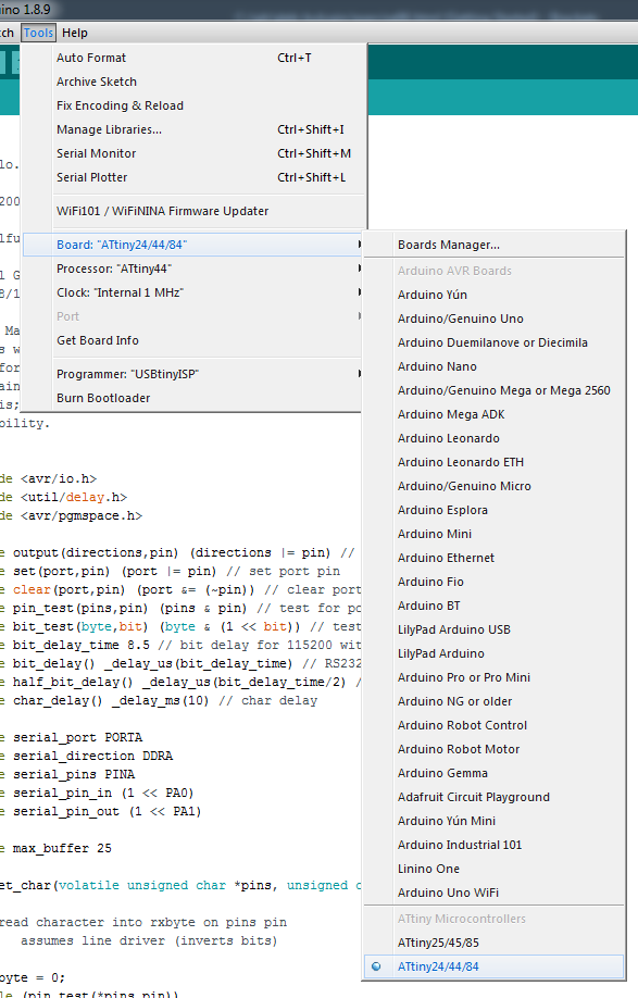
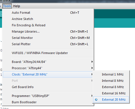
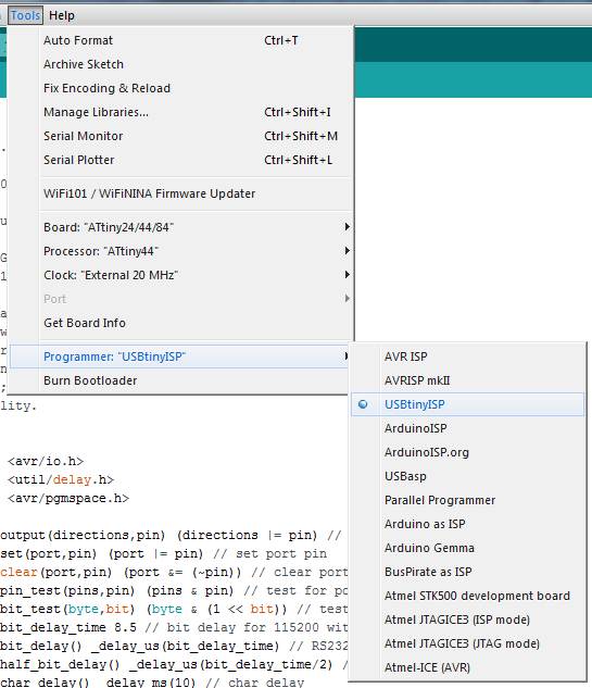
On the Electronics Design week assignment I installed and set up Arduino IDE. I explained the whole setup process on the assignment page. In Tools I set:
Board: ATtiny23/44/84
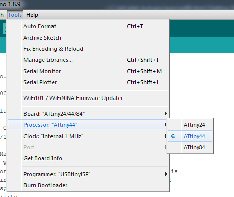
Processor: ATtiny44
Clock: external 20MHz
Port: COM6 (might be different)
Programmer: USbtinyISP
More detailed tutorial in the box below:
Full tutorial I followed to set the Arduino IDE can be found here
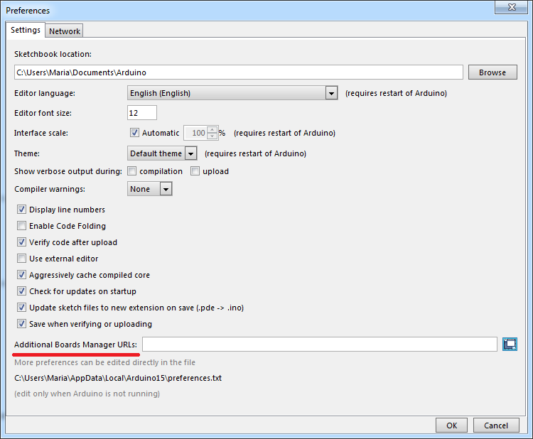
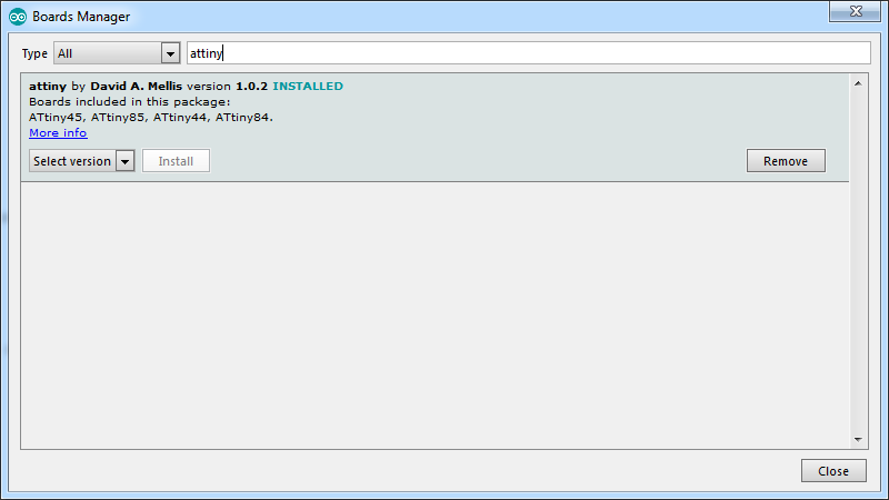
First things first, by deafult Arduino IDE does not support ATtiny. But it's reale easy thing to fix: open Preferences(File/Preferences of Ctrl+Comma)
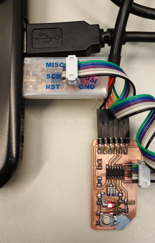
Hardware for this week:
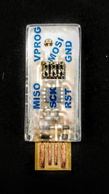 |
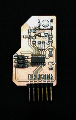 |
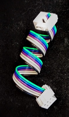 |
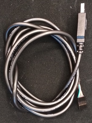 |
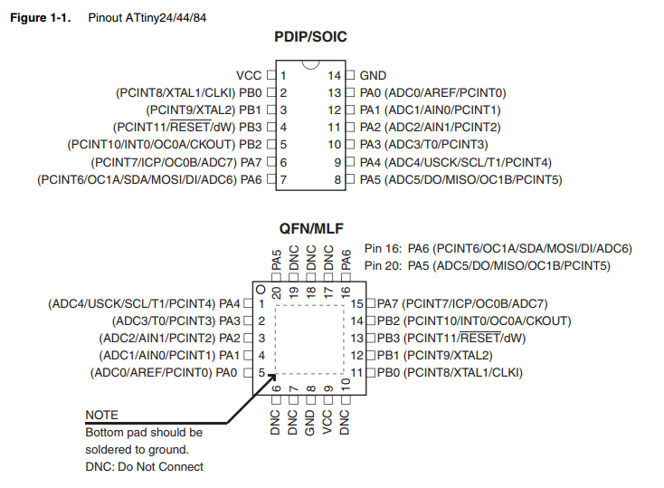
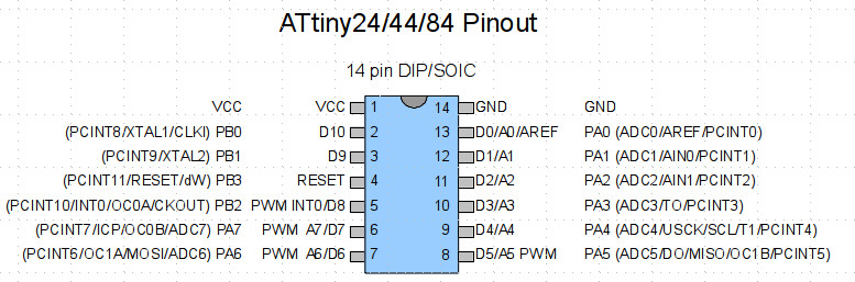
Using Arduino IDE is nice and easy, but the I didn't manage to use the pin map from the data sheet. I've found this manual on the internet. There I've found the most useful image so far.
//base on Antti's Fabblink sketch
(http://archive.fabacademy.org/archives/2016/fablaboulu/students/161/Assignment8.html)
//the LED is connected to the pin 5(PB2) and a button to 6(A7)
//To use them in the program Antti put them into constants:

const int buttonPin = 7; //button pin
const int ledPin = 8;  //LED pin
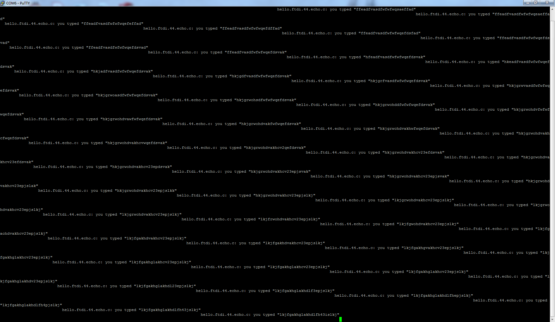
On my Hello Word board I had Neil's echo program. It worked fine (check the code)
Next thing I did, I edited exemple code from Arduino exemples. This is the exemple Antti edited in his documentation (I've found it while I was working on my Elecronics production week documentation).
From constant shining I made the LED blink. It was very easy. I added a delay (changing the delay value will change the blinking frequency)
/*
Fablab circuit blink
This code is modified by Gleb Bulygin from the example code in
http://www.arduino.cc/en/Tutorial/Button
*/

const int buttonPin = 7;     // The numbe of the button pin. Number from the pin map
const int ledPin =  8;      // the number of the LED pin. Number from the pin map

int buttonStatus = 0;         // "register" to check button status

// inputs and outputs
// LED active = high
void setup() {
  pinMode(ledPin, OUTPUT);
  pinMode(buttonPin, INPUT);
}

// main loop
void loop() {
  buttonStatus = digitalRead(buttonPin);

if (buttonStatus == LOW) {
    // turn LED on:
  digitalWrite(ledPin, HIGH);
  delay (5);
  //turn LED off
  digitalWrite(ledPin, LOW);
  delay (5);
}

else {
    // turn LED off:
    digitalWrite(ledPin, LOW);
  }
}
Next, I've found an example for slowly dimming the LED. I edited the code that way, that, when the button is preesed, the LED will slowly brighen up and, after reching max brightness value, it will slowly fade. If it is not pressed, the LED will just blink. It worked very nice.
/*
Fablab circuit Fade
This code is modified by Gleb Bulygin from the example code in
http://www.arduino.cc/en/Tutorial/Fade
*/


int buttonStatus = 0;
const int buttonPin = 7;
const int ledpin = 8;           // the PWM pin the LED is attached to
int brightness = 0;    // how bright the LED is
int fadeAmount = 2;    // how many points to fade the LED by

// the setup routine runs once when you press reset:
void setup() {
  // declare pin 8 to be an output:
  pinMode(ledpin, OUTPUT);
  pinMode(buttonPin, INPUT);
}

// the loop routine runs over and over again forever:
void loop() {
  buttonStatus = digitalRead(buttonPin);


  if (buttonStatus == LOW) {
    // set the brightness of pin 8:
    analogWrite(ledpin, brightness);
    // change the brightness for next time through the loop:
    brightness = brightness + fadeAmount;

    // reverse the direction of the fading at the ends of the fade:
    if (brightness <= 0 || brightness >= 255) {
      fadeAmount = -fadeAmount;
    }
    // wait for 30 milliseconds to see the dimming effect
    delay(30);
  }
  else {
    digitalWrite(ledpin, HIGH);
    delay (50);
    //turn LED off
    digitalWrite(ledpin, LOW);
    delay (50);
  }
}
4. Results of the week
- My Hello Word board is still working. Unbent, unburnt, unbroken.
- I can read button status and operate the LED. After editing the Fade example I was very happy with the result.
- I was trying to use SoftwareSerial.h library to send something to the serial port, but all my attempts failed. So far, I haven't found any working code for ATtiny44.
- I installed Atmel Studio 7.0 as a back up option.
- I took a quick look at ATmega datasheet. It is very possible that I will use ATmega in my final project.