Week 5. Electronics Production
Go to:
Group Assignment
Characterize the design rules for your PCB production process
This week is dedicated to PCB fabrication by using milling processes. I was exploring it with:
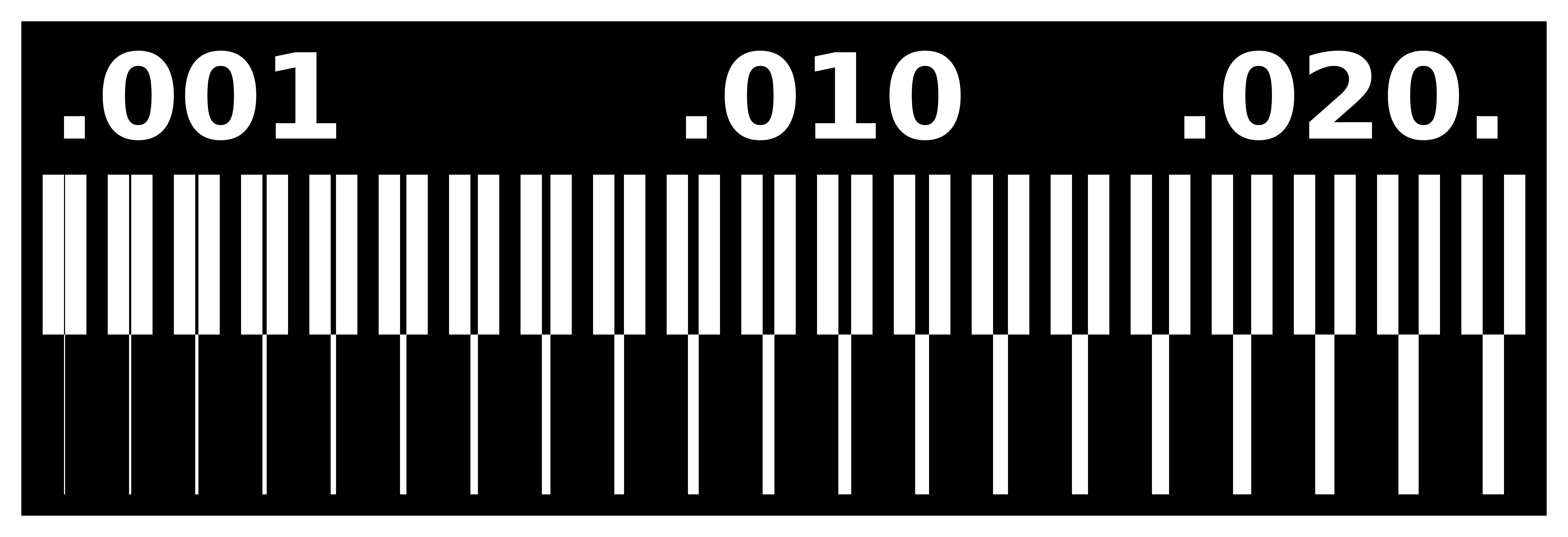
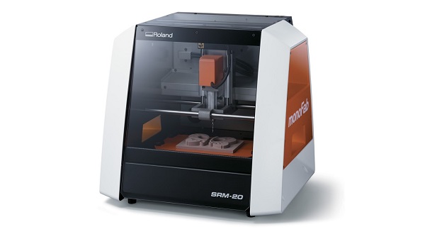
This week we used Roland SRM-20 milling machine. From the software we can control x,y,z position of the drill and rotating speed. Before starting tests we cleaned the machine properly and made sure that the working surface is flat. Then we downloaded Linetest.png file and using mods we made a .rml file for the milling machine.
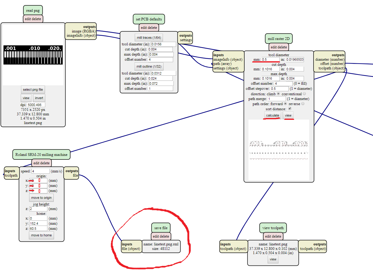
To open this program go to mods then right click on the window and select: programs/open server program/SRM-20(PCB). And we want to save file, not send it to the machine, so delete WebSocket device module and right click on the window and select: modules/open server module/file (save). Then set origin coordinates to (0,0,0) and connect output Roland SRM-20 milling machine and input save file. Open your png file in read png module. Click on mill traces 2D or mill outline in set PCB deafauls. Then define tool diameter and cut depth in mill raster 2D module and press calculate. testlines.png.rml file will be downloaded automatically (this file you should open in the milling machine software). Click view button to check if the created path is correct.
|
|
|
|
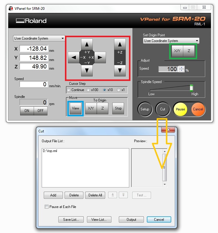
First step is to set the origin point. X,Y and Z buttons (marked with a red rectangle) will move the jog by 1mm, 0.1mm or 0,01mm depending on the chosen step. Continuous mode will move the jog while the button is pressed. FabLab tutors strong recommendation is NOT to use it moving along the Z-axis. So, move the jog to the left-bottom corner of the material, set the X,Y starting point (X/Y button in the green rectangle) then move it down along the Z-axis until it will be less than 1mm to the surface. Then you can loose the clutch and carefully drop the milling bit to the surface. Don't forget to tighten the clutch after. Define that point as zero-Z. I like to define the zero Z point a little bit higher than the surface and start the job. That way I can see if the stock plate is not plane enogh and I can fix it with no harm done. View button will move the platform forward so you can take a look how it's going. After all zero-points are defined press Cut and choose a .rml file. When you press Output the job will start immideately. At every point of the job you can Pause, move to the view position, take a look and continue or cancel the process.
Simplified procedure of fabrication/milling process of PCBs:
- Design the board
- Check the design rules
- Export monochrome the image with DPI=1000 or more
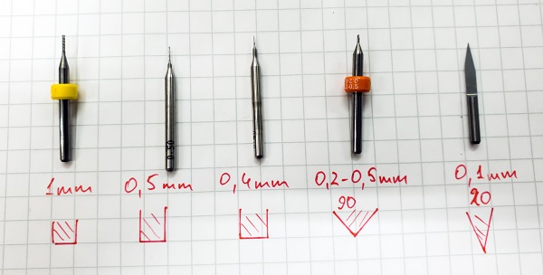
- Choose proper milling bits for milling the traces and outcut
- Go to Mods and make the .rml files
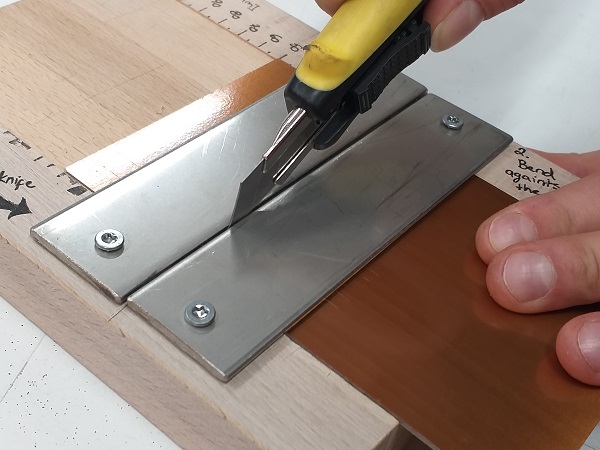
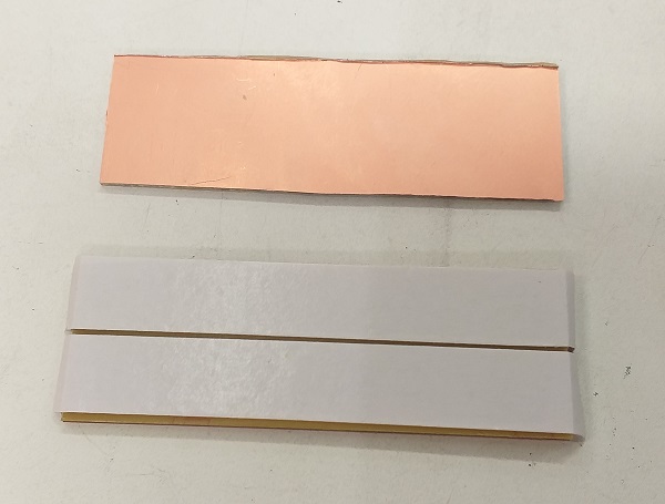
- Find suitable substrate (the smaller the substrate the easier to make it plane)
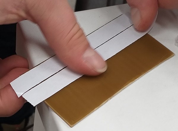
- Put doublesided tape on the back side of the substrate
- Put the milling bit for the traces in the machine clutch
- Put the substrate in the machine
- Set the zero for X,Y (bottom-left corner)
- Lower the Z, drop the milling bit to the surface, tighten the clutch, set zero Z
- Press Cut
- Add yours .rml file to the list (I remove files I don't need from the list)
- Press Output
- Wait until traces are milled and move to the view position
- Remove the shavings and change the milling bit for the outcut
- Move to X/Y orign
- DO NOT redefine X/Y zero point!
- Set the zero Z again
- Press Cut
- Add an outcut .rml file and press Output
- Wait untill it done. Move to the view. Clean the machine.
- Clean the surface of your board with a steel wool. It makes soldering easier.
Limitations
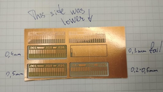
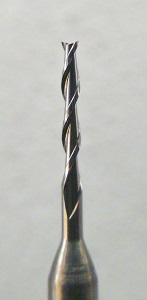
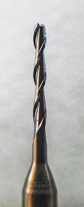
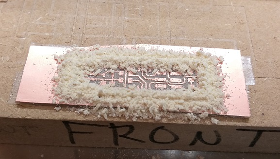
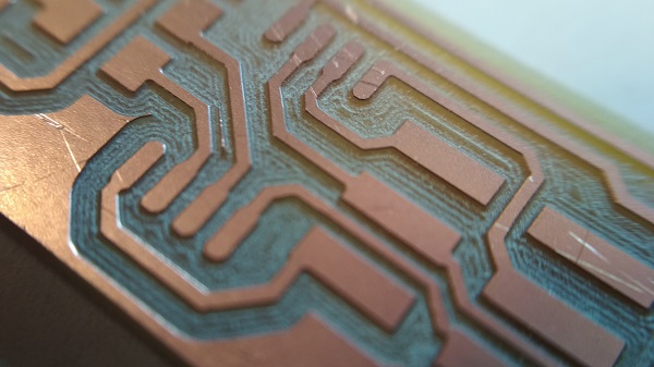
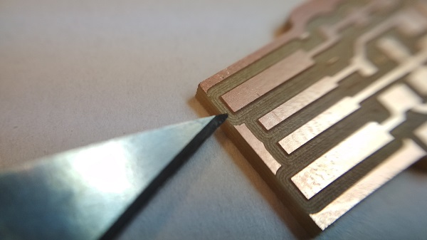
So far no problems occurred. However, there must be something, which is stopping us from creating ultra-small circuits. Something, which prevents from unbelievably precise PCBs. Unfortunately there is couple things. First of all drill size is somewhat limiting us in the milling. Second case is step of motors, this is also not finite and have some strict values. Nevertheless it is usually smaller than used drill and third factor. Even that we are using really small drill sizes, when drill routes are close to each other they will rip copper from the surface. Leaving nothing but an empty hole. We created a test drill to estimate couple constants
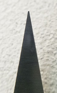
Drill_1: 0.2 - 0.05 [mm] 90 degree milling tip
| How close traces may be placed: | size of drill head |
| What is minimal width of a trace: | 0.001 mm |
| What is ability to drill between traces: | till 0.01 mm |
| Result | Drill | Size/Shape |
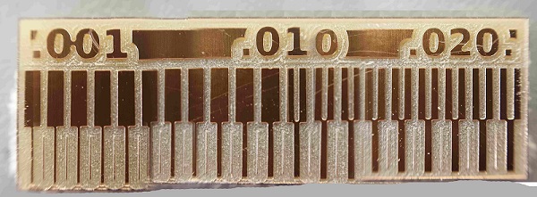 | | 0.2 - 0.05 [mm] V-shape |
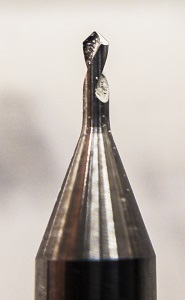
Drill_2: 0.4 [mm] flat milling tip
| How close traces may be placed: | size of drill head |
| What is minimal width of a trace: | 0.001 mm |
| What is ability to drill between traces: | till 0.4mm mm |
| Result | Drill | Size/Shape |
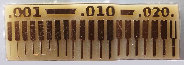 | | 0,4 [mm] Flat |
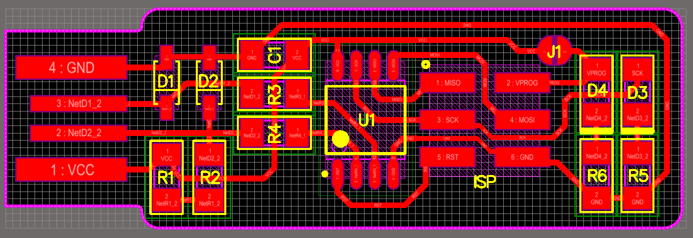
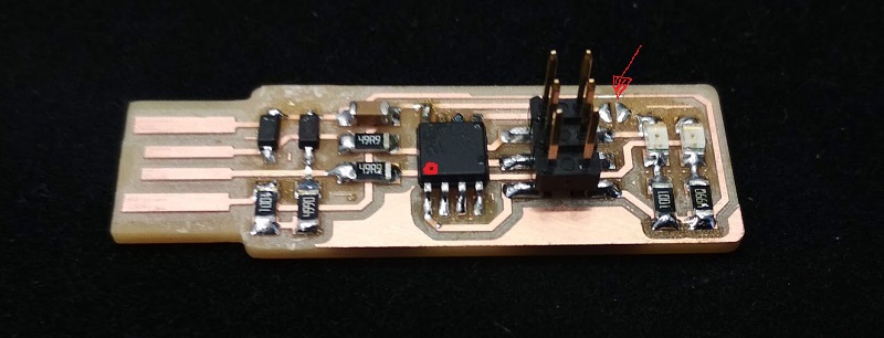
2. Making an in-circuit programmer
To make it fast and right I followed Brians tutorial.
Then I downloaded:
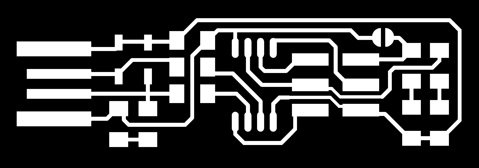
And using mods I created .rml file for the traces and for outline. To mill my board I used 0,2-0,5 mm V-shape milling bit for Traces and 1mm flat — for Outline. I saved .rml files. With V-panel I set the origin. Then I pressedCut, removed previous files from the queue and added my file
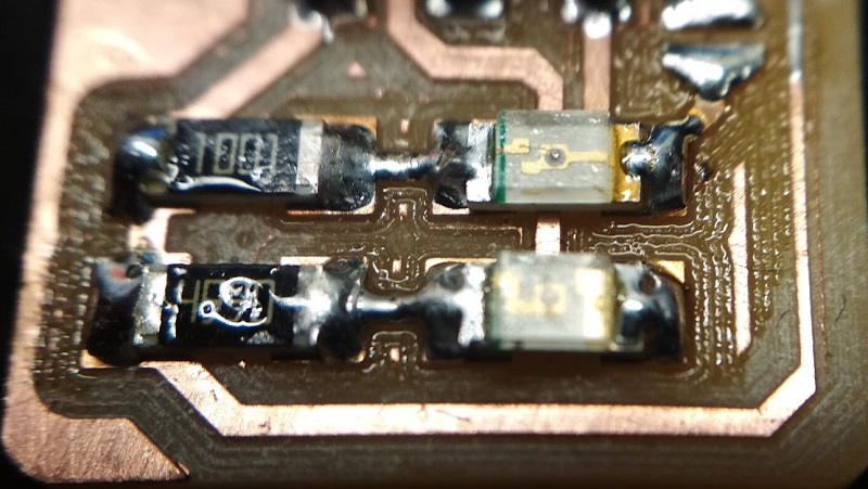
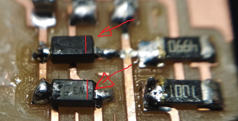
Components list:
- 1x ATtiny45 or ATtiny85
- 2x 1kΩ resistors
- 2x 499Ω resistors
- 2x 49Ω resistors
- 2x 3.3v zener diodes
- 1x clear red LED
- 1x clear green LED
- 1x 100nF capacitor
- 1x 2x3 pin header
3. Programming

Mikko Toivonen helped me to program my programmer using his programmer. Most likely, it is better to do the programming part from Linux (just follow the tutorial on this page), but my laptop with Linux Mint onboard went to his digital Valhalla so here's tutorial for Windows. It is based on this tutorial and Kati's documentation for this week from previous year. I walked through the process and made the screenshots by myself, but, since I have my programmer already programmed, I couldn't complete two final steps. By all meanings it must work just fine.
Installations for setting up the development environmen
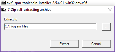
1) First of all, Install the Atmel AVR Toolchain for Windows from Atmel's site and ran the installer. Pay attention to extract the files to C:\Program Files.
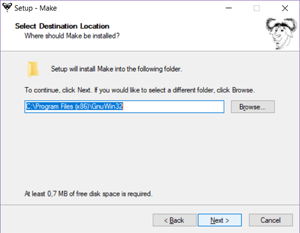
2) Next, download Gnu Make and launch the installer. Accept the default location for the installation, which seemed to be C:\Program Files (x86)\GnuWin32.
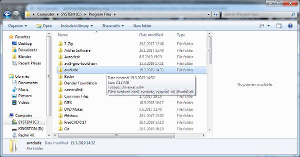
3) Download avrdude, unzipp the folder and copy the archive 'avrude' inside of it to C:\Program Files.
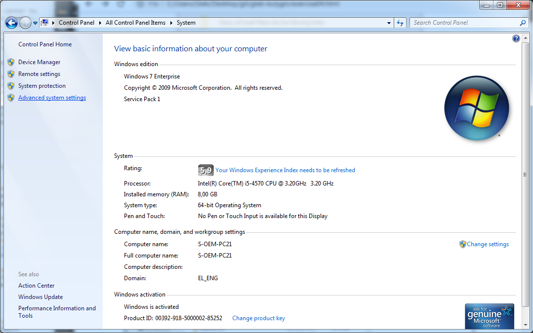
For finishing these tool installations, modify the Paths in order to tell Windows the locations of the tools. Go to Control Panel/System
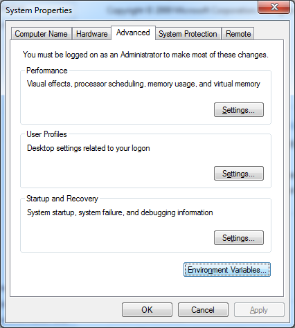
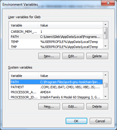
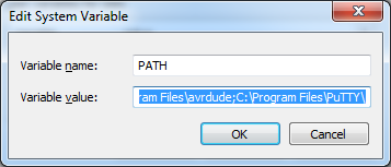
Paste in the Variable value paths to the tools using ";" as a divider:
- C:\Program Files\avr8-gnu-toolchain\bin
- C:\Program Files (x86)\GnuWin32\bin
- C:\Program Files\avrdude
This is how it should look like:
C:\Program Files\avr8-gnu-toolchain\bin;C:\Program Files (x86)\GnuWin32\bin;C:\Program Files\avrdude;
Don't forget to save changes (OK→OK→OK). If something goes wrong check this tutorial.
4) Next step and as a last part of the installations, was to install drivers for my programmer. For Windows users, Brian advices us to use a helpful tool Zadig. On this step you need to borrow already working programmer from somebody. Plug it to usb 2.0 port and start the install the driver.
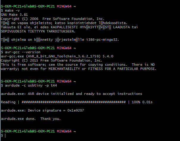
Checking the installations and commands to make sure everything works
In order to check that everything are in the right folders and installations are finished successfully, I used Git Bash for Windows, but Command prompt must work as well
Type next commands in terminal and press Enter. If you get a "command not found" error instead, re-check your installations.
make -v
avr-gcc --version
avrdude -c usbtiny -p t45
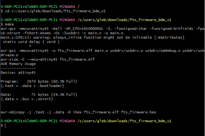
Building the Firmware
Downloaded the firmware source code and extract the zip file. In Git Bash, navigate into the source code directory, and ran make. The command builds the fts_firmware.hex -file
make
Programming the ATtiny45
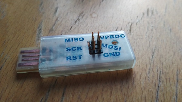
Plug your board and the programmer you use to the USB 2.0 ports (extension cables are recommended). Red LED on your board must shine now. Then connect ISP headers via cable. Be careful with the pin layout. I usually look at the GND pin position.
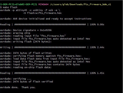
Run make, which erase the target chip, and program its flash memory with the contents of the fts_firmware.hex -file. From the processes below can be seen how avrdude erased (erasing chip), programmed (writing flash), and verified (verifying flash memory against fts_firmware.hex) the chip.
make flash
After programming the flash memory, set the configuration fuses. The fuses control where the microcontroller gets its clock source from.
[Also, after making sure that the board has succesfully programmed to be a programmer, the fuse disabling the reset pin and turning it into a regular GPIO in will be set. This allows the chip use the reset pin for programming other boards, but will disable the ability for this chip to be reprogrammed.]
make fuses

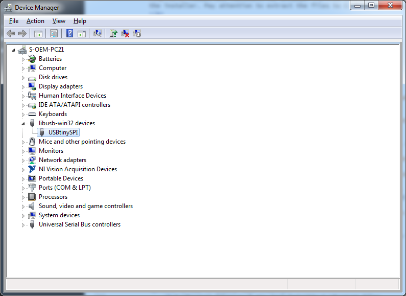
Now you board must be visible in the Device manager.
Blowing the Reset Fuse
Two steps left.
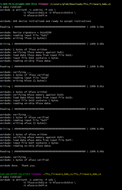
Turne the ATtiny45's reset pin into a GPIO pin by finishing the fuses using make rstdisbl command, which does the same as the 'make fuses' did before, but adds that final command disabling the ability to reprogram this chip anymore.
make rstdisbl

Final step is to disconnect the Vcc from the Vprog pin on the ISP header by removing the temporarily jumper (on the schematic marked as J1). Heat it with the soldering iron and remove the solder with a solder removing tool or a piece of a wire braid.

4. Shell
This part I did later than the rest of the documentation, but it belongs here. The programmer does not fit in the USB port. So it needed a nice case. I designed it in Fusion360 and printed it on Fromlabs Form2. I'm very satisfied with it.
5. Results of the week
- I milled my first pcb. So far it looks like etching is much easier and faster. Anyway, the resolution of the SRM-20 milling machine is very impressive.
- I made a fully functional AVR ISP programmer.
- Mikko helped me with programming my programmer (using his programmer), but while writing documentation I got a deeper understanding about all processes.
- Programming is much easier on Linux.
- I designed a very nice case for the programmer.