Week 12. Output devices
Go to:
1. Group work
Task: Measure the power consumption of an output device.
Group:
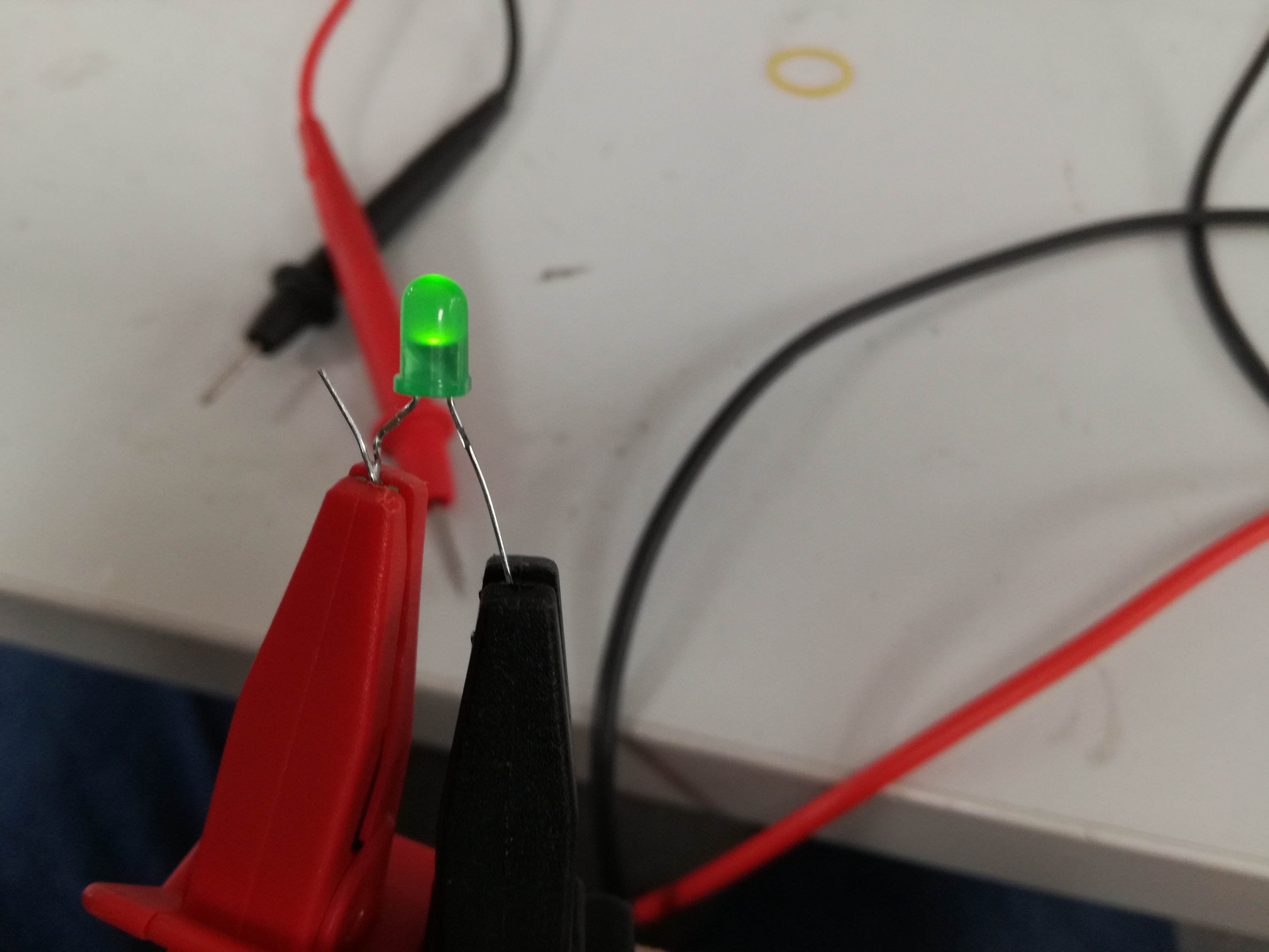
Green LED
There are no more obvious choice as Light emitting diodes. Results are visible with bare eye and connection is very simple. We have found some random green LED on burned board. Our decision was to measure forward voltage to current characteristics. From this power might be easily calculated as Power = Voltage x Current.
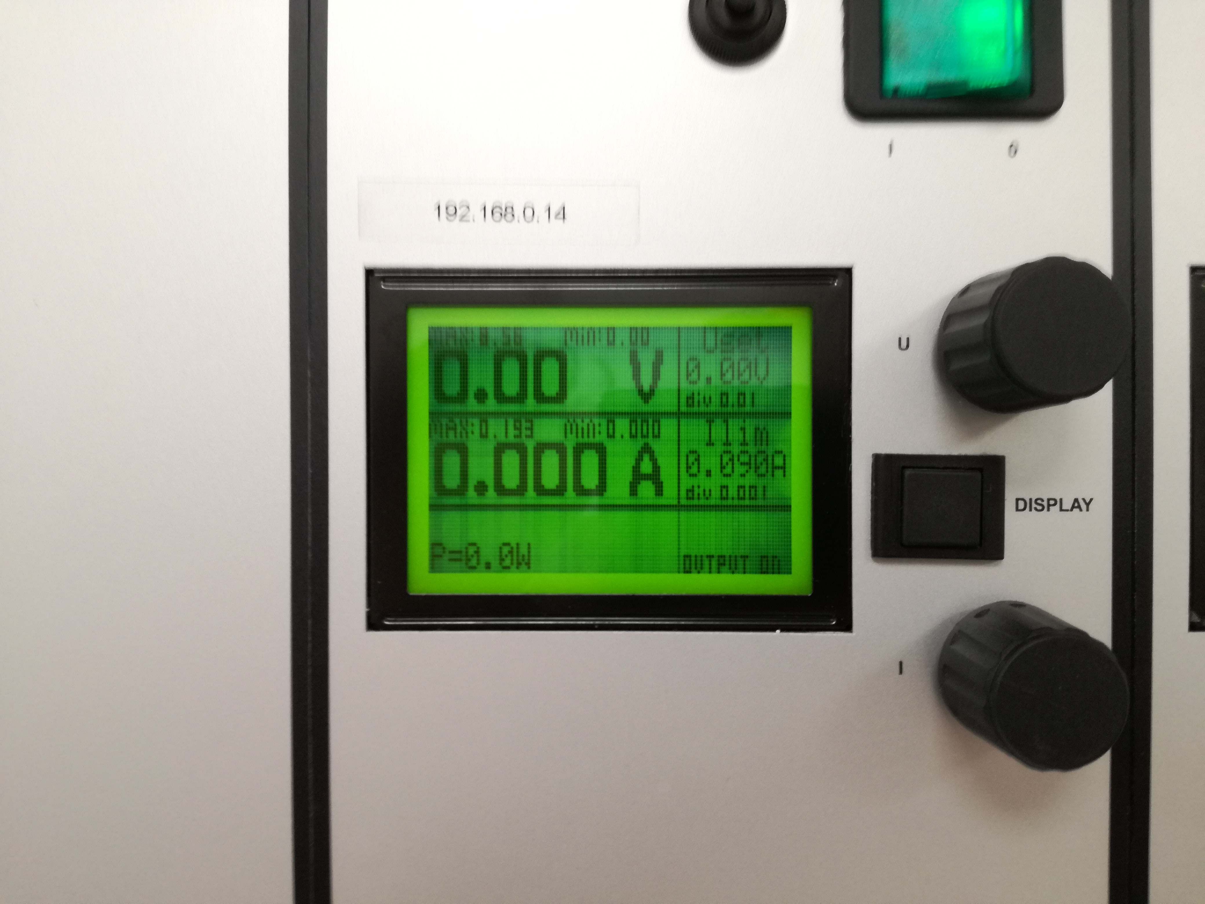
We have connected our LED to the laboratory power supply. It is smart construction as it has both current and voltage limited output. Meaning it would be really difficult to burn our LED but we manged.
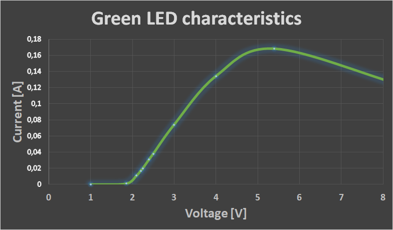
We were feeding LED with voltage, where our current was limited every time. We managed to obtain full characteristics from barely glowing to final breath of our LED. Results are shown below.
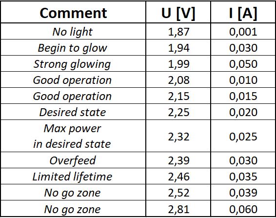
We managed to write down our observations during measuring process. Observations below:
Motherboard Fan
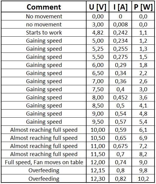
Our next choice was cooling fan. This was doing its best to cool down some electrical circuit. Nominal values were 12 Volts at 0.9 Ampere. This time we have shown some mercy and did not destroy measured element. Once again we used our laboratory power supply. This time we limited current to maximum value of 0.9 Amp and played with voltage. We managed to obtain both Current vs Voltage and Power vs Voltage characteristics.
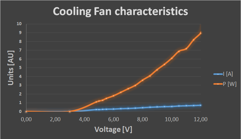
Once again we wrote down our observations during measuring process. Observations below:
Individual Assignment
This week is very important for me, because it's directly linked to my final project. I will have only one output: Addresed RGBW 5050 LED stripe with 144 LEDs/m. I ordered it from here. The real magic of this is that the color of every LED can be controlled with just one ouput pin on the PCB.
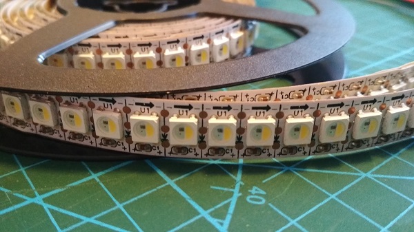
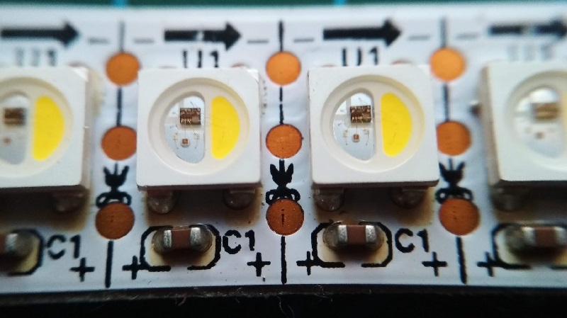
To program my board I use Arduino IDE (more about programming process on Embedded Programming week). For my final project I need about 270 LEDs (or 1,85m of LED strip). I have 2m of those, so I cut myself a 15 LEDs (about 10sm) piece for the tests. I soldered female headed wiers to the
This week I have been using my version of Hello Word made on previous week. I just don't use the sencor board.
For operating RGBW LED strip there is a specia library for Arduino IDE Adafruit_NeoPixel.h. It is really easy to use. Just include it in your sketch:
#include <Adafruit_NeoPixel.h>
Next, I opened one of the exampeles RGBW_NEOpixel_standard_test and tried to load to my board. First I got an error:
CPU speed not supported
I have a 20MHz external clock on my soldered on my PCB. Process of trouble shooting started here. Spoiler: everything worked with:
Clock: Internal 8MHz
Then I connected LED strip to 4pin header on my PCB. The header has 4 pins: Vcc, GND, ATtiny pin 5, ATtiny pin 6. I'm using ATtiny pin 5 as control pin for the led strip (declared as 8 in the sketch). How to use ATtiny pins in Arduino IDE is tried to explain on Embedded Programming week page.
The sketch was too big for ATtiny, so I removed everything but colorWipe function and burned it to my board. I leave the code I used below.
// NeoPixel test program showing use of the WHITE channel for RGBW
// pixels only (won't look correct on regular RGB NeoPixel strips).

#include <Adafruit_NeoPixel.h>
#ifdef __AVR__
 #include <avr/power.h> // Required for 16 MHz Adafruit Trinket
#endif

#define LED_PIN     8 //5pin on ATtiny44

// How many NeoPixels are attached to the Arduino?
#define LED_COUNT  15

// NeoPixel brightness, 0 (min) to 255 (max)
#define BRIGHTNESS 50
// Declare our NeoPixel strip object:
Adafruit_NeoPixel strip(LED_COUNT, LED_PIN, NEO_GRBW + NEO_KHZ800);
// Argument 1 = Number of pixels in NeoPixel strip
// Argument 2 = Arduino pin number (most are valid)
// Argument 3 = Pixel type flags, add together as needed:
//   NEO_KHZ800  800 KHz bitstream (most NeoPixel products w/WS2812 LEDs)
//   NEO_KHZ400  400 KHz (classic 'v1' (not v2) FLORA pixels, WS2811 drivers)
//   NEO_GRB     Pixels are wired for GRB bitstream (most NeoPixel products)
//   NEO_RGB     Pixels are wired for RGB bitstream (v1 FLORA pixels, not v2)
//   NEO_RGBW    Pixels are wired for RGBW bitstream (NeoPixel RGBW products)

void setup() {
   strip.begin();           // INITIALIZE NeoPixel strip object (REQUIRED)
  strip.show();            // Turn OFF all pixels ASAP
  strip.setBrightness(BRIGHTNESS); // Set BRIGHTNESS to about 1/5 (max = 255)
}

void loop() {
  // Fill along the length of the strip in various colors...
  colorWipe(strip.Color(255, 0, 0, 0)     , 50); // Red
  colorWipe(strip.Color(0, 255, 0, 0)     , 50); // Green
  colorWipe(strip.Color(0, 0, 255, 0)     , 50); // Blue
  colorWipe(strip.Color(0, 0, 0, 255), 50); // True white (not RGB white)
}

// Fill strip pixels one after another with a color. Strip is NOT cleared
// first; anything there will be covered pixel by pixel. Pass in color
// (as a single 'packed' 32-bit value, which you can get by calling
// strip.Color(red, green, blue) as shown in the loop() function above),
// and a delay time (in milliseconds) between pixels.
void colorWipe(uint32_t color, int wait) {
  for(int i=0; i<strip.numPixels(); i++) { // For each pixel in strip...
    strip.setPixelColor(i, color);         //  Set pixel's color (in RAM)
    strip.show();                          //  Update strip to match
    delay(wait);                           //  Pause for a moment
  }
}