Week 11. Input Devices
Go to:
1. Group work
Task: Probe an input device's analog levels and digital signals.
>
Group:
Photovoltaics
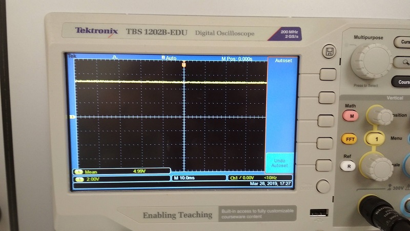
We decided to start with measuring signals from analog input devices. We have found couple photovoltaic modules. Those were rather small size compared to solar panels, which might be found on the roof. Nevertheless, we managed to obtain some decent voltage levels. We tried the differences between fluorescent lamp and Smartphone LED.
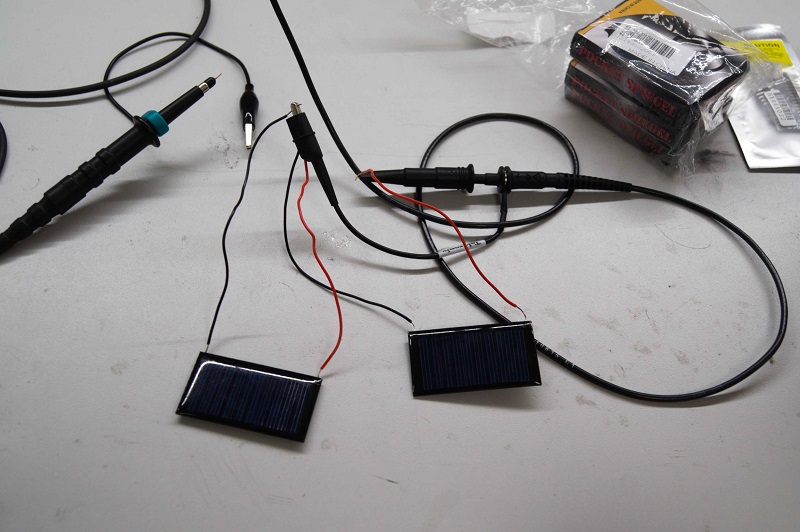
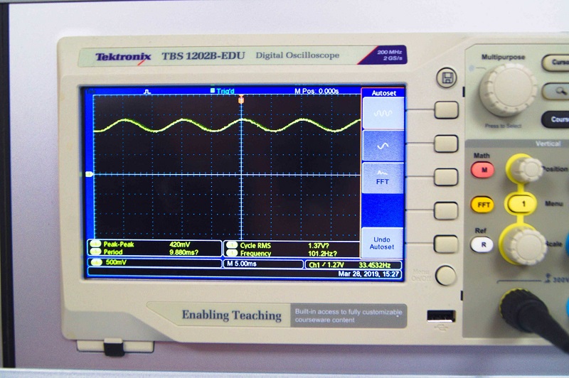
Our test unites were connected in series in order to obtain higher voltage values. We were using oscilloscope to measure output. We could have used multimeter with the same success.
Differences are easily visibly. LED provided stable volatage level, where lamp was flickering with 50 Hz freqency. This is the obviously unwanted in powering ICs, should be removed with diode bridge or other rectifier.
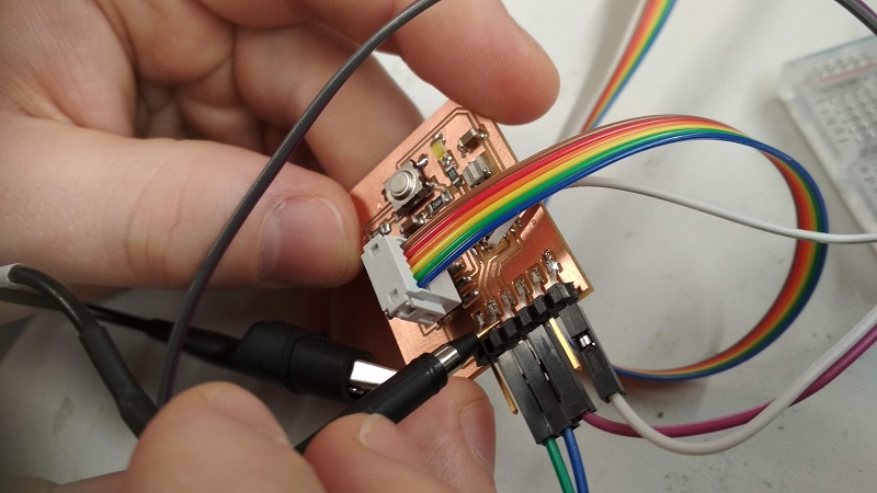
Photoresistor and LED
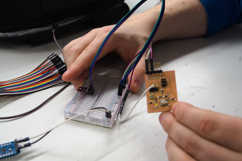
We managed this part quite well. We decided to work with ATTiny from now on. We have found photoresistor, element, which changes its resistance in presence of light. Our unit was nice, already embedded on the PCB. Circuit was simple - voltage divider. Value of first resistor is fixed, where photoresistor resistance varies. Voltage across photoresistor will change depending on light strength. There are three pins, which needs to be connected. Power line (TTL logic values), ground and signal pin - output value.
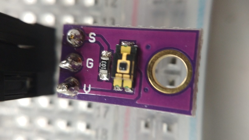
Just to be sure that our device is working properly, we have checked values using oscilloscope. Circuit was powered from USB port. Everything worked as expected.
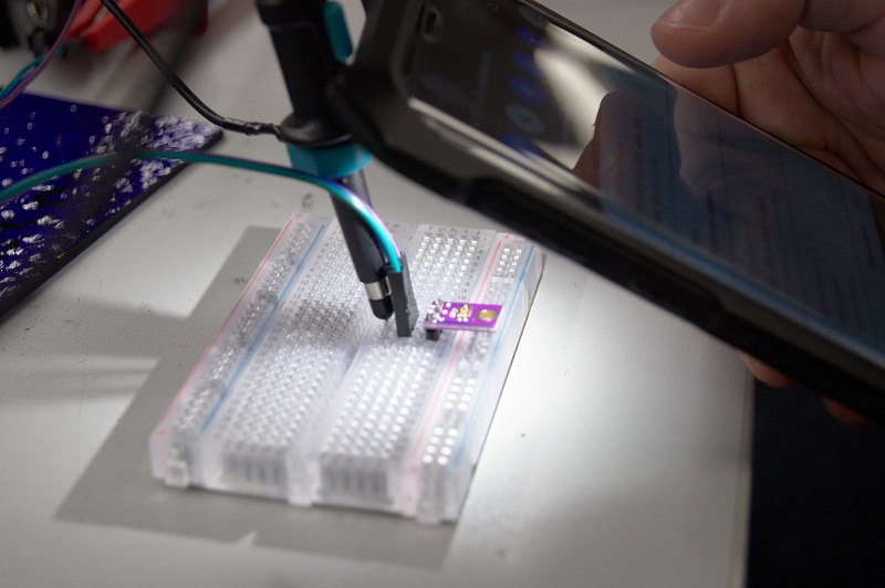
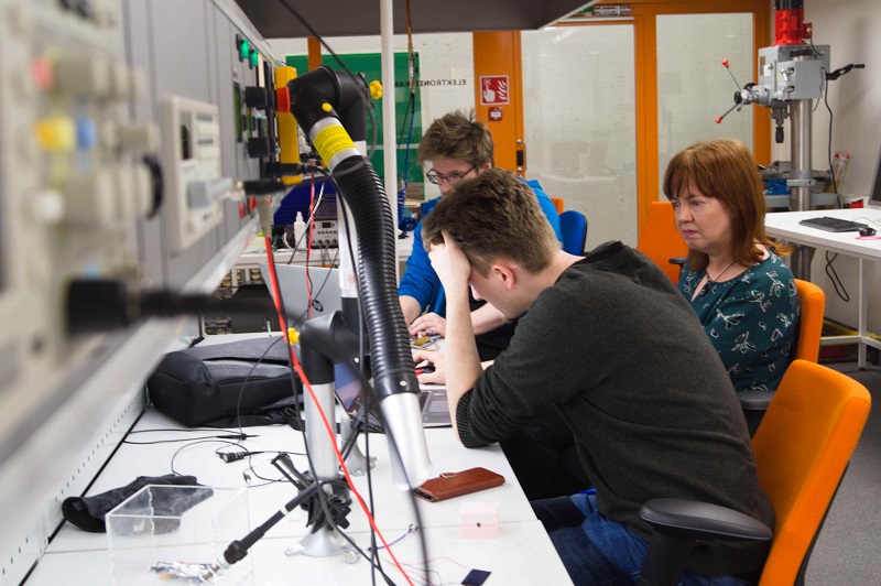
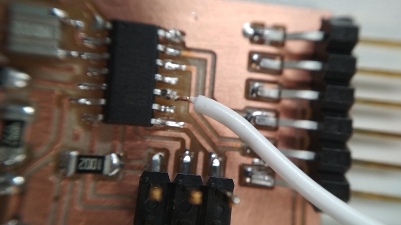
As said before our plan was to use ATTiny. Using Arduino IDE, we create a code, which was turning LED on every time photoresistor was lacking light. Our preiously designed board didn't have pinheaders to connect with output boards, because of that we simply soldered signal line to unused port.
Programming was interesting, as unluckily laptop, which we were using had very limited amounts of USB ports. Regards to Hewlett-Packard Anyway, we managed and we continued our journey.
.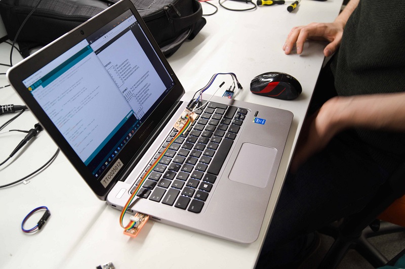
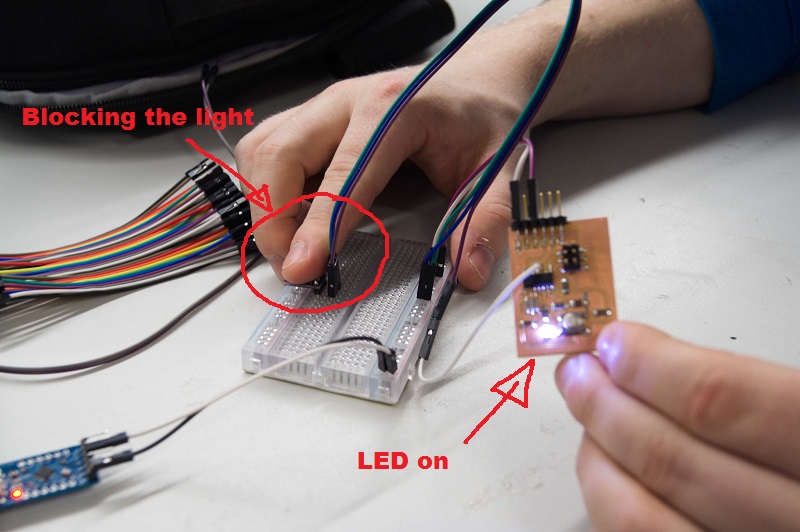
After programming circuit was supplied from USB port. It didn't require more than two connection, 5V and GND. After couple attempts we managed to make it fully functional. It could be useful as working principle is similar to lamps with dusk sensor. Below some a little prof that it worked.
|
|
Photoresistor and Serial port
Alright, analog input to analog output worked nicely. Finally, we decided to test analog to digital version. For this instance, ATtiny will send some characters depending on what it will sense with previously used photoresistor. This time connection was a bit more complicated.
We have improved Arduino code, every time there will be no light detected "0" will be send, where any voltage (create by light) above given threshold will send "1" over serial port. This would be easily readable using putty. After couple attempts we achieved it.
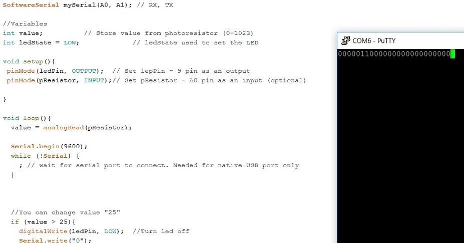
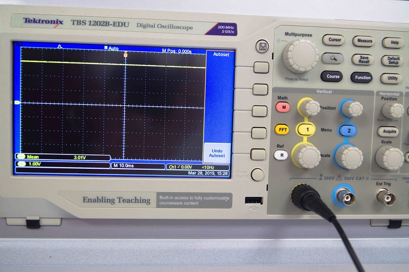
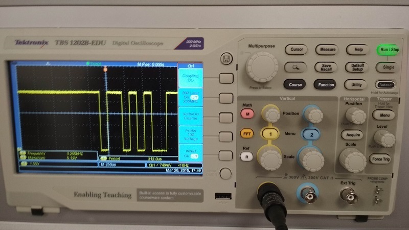
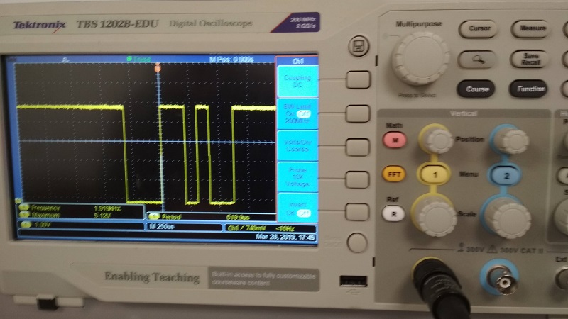
After a moment we decided to investigate arduino function Serial.Wire and instead using characters, we used ASCII codes. We picked two random numbers: "43" and "44". It turned out that first was plus sign and second was coma. Fair enough. We measured transmission using oscilloscope. Everything worked well.
Both Arduino codes are available to download. There are very descriptive comments on each functionality
|
|
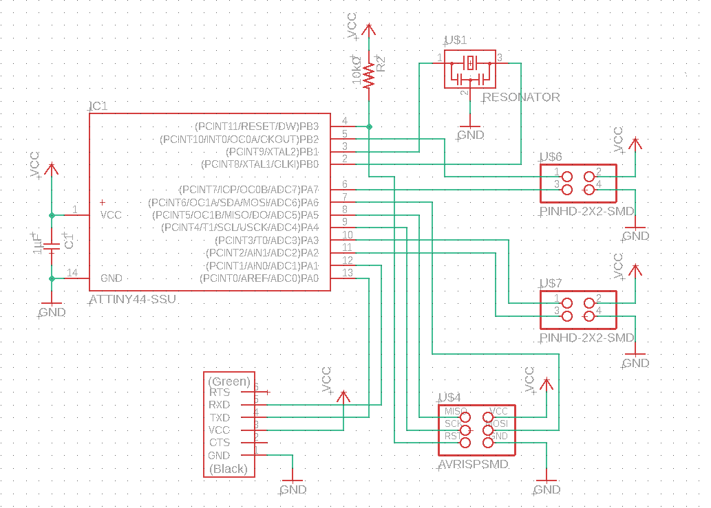
2. Schematic
Task: Measure something: add a sensor to a microcontroller board that you have designed and read it.
For this week I modified my Hello World board from week 7. I ripped off button and LED from the board and add 2 2x2 pin headers to be able to reprogramm it and reuse in the future. I like the way it looks like now.
At first I wanted to use Piezo sensor to make a smart drun pad. But this project failed because of the following reasons:
- I am a lousy drummer, even the smartest drum pad can't fix it
- This is not even remotly connected to my final project
- I didn't have any suitable rubber and I wasn't sure that Oomoo 30 can take proper beating
So I continued my journey with Roland SRM-20 milling machine in one hand and a phototransistor circuit in another.
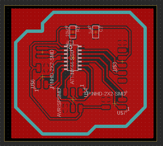
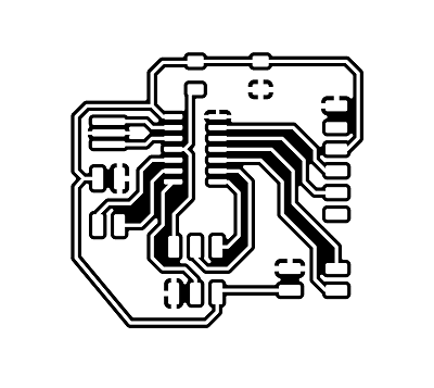
3. The Board
From Eagle I exported .png images and created the toolpaths using MODS. I use 0.2-0.5 mm V-shape milling bit and for fine cut I use a small trick: after setting the Z-coordinate (milling bit touching the surface of the board) I raise the origin by 0.015-0.025mm and define this poins as a zero Z. Then I start the traces milling process. Usually, I get nice result on this point, but if something is wrong the bit does not go too deep into the board and I have time to fix it without harm done.
|

|
|

|
![]()
Components lists:
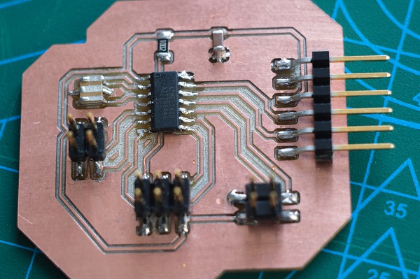
MAIN BOARD:
| 1. | ATTINY44-SSU | x1 |
| 2. | Resonator | x1 |
| 3. | Capasitor 1µF | x1 |
| 4. | Resistor 10kΩ | x1 |
| 5. | 2x2 SMD Pin Header | x2 |
| 6. | 2x3 SMD Pin Header | x1 |
| 7. | FTDI-SMD-Header | x1 |
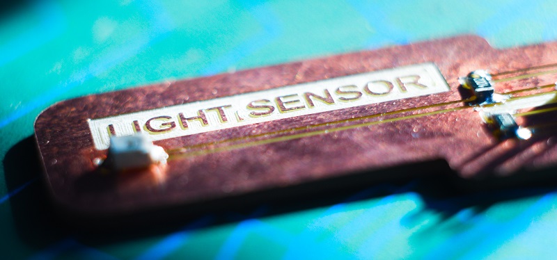
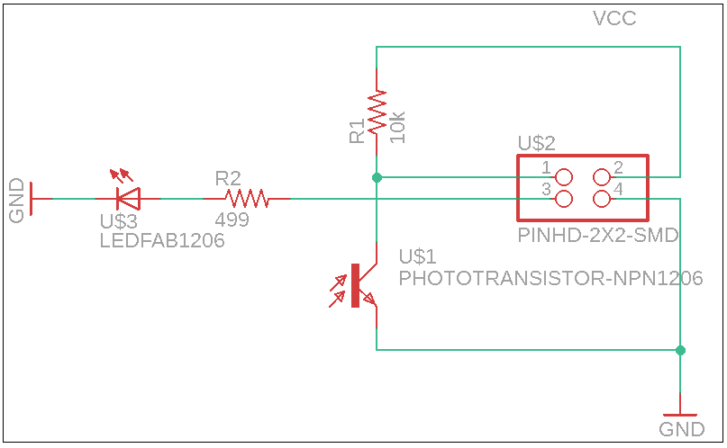
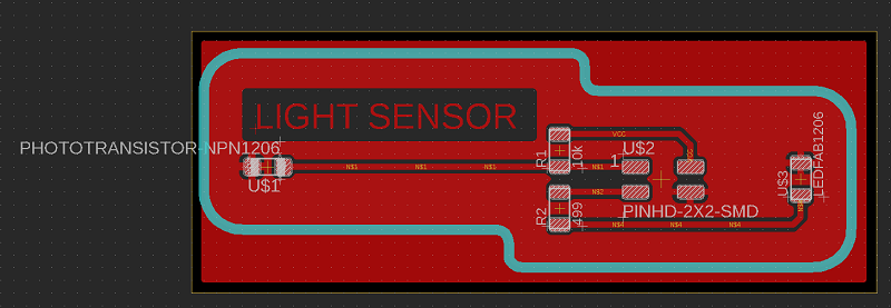
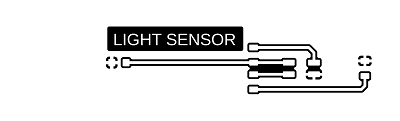
LIGHT SENSOR:
| 1. | PHOTOTRANSISTOR-NPN1206 Phototransistor OP580DA |
x1 |
| 2. | Resistor 10kΩ | x1 |
| 3. | Resistor 499Ω | x1 |
| 4. | LED1206 clear-white | x1 |
| 5. | 2x2 SMD Pin Header | x1 |
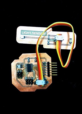
During this week I had some problems with my programmer (I made a new one later) so I asked my frind Lukasz for help. Using Arduiono we made a simple program which turns on the LED constantly if there's light detected and blinks it when there's no light. Later we changet it to turn off the LED when there's no light and removed the delay for easyer demonstration. The sensor is connected to ATTINY PA3(10) and the LED to PA2(11).
4. The Results of the week
- I designed and produced a new Hello World board with possibility to use modules instead of milling a new board. I really like this version. It's simple and useful.
- The Light Sensor works fine.
- I made a new programmer for myself because my old one refused to work.
- I'm thinking about adding the photosensor to my final project, but for now I'm not sure if this feature is really needed.
- LEDs for my final project arrived and wait for next week dedicated to Output.