
Overview
I am working with my extended hello world board with a button and green led, which I created in the electronics design week. First of all, I went and read the manual for the attiny44. Then I programmed it to let the led blink, using the USBTinyISP and also an Arduino as a programmer. Then I programmed it to use the button to light the led up.
Learning from the datasheet
The first thing I learned which helped me was the pinout with all the different pins of the attiny44 and the corresponding functions and names behind it. I used this while designing the board and also while programming to look up the pins I connected something too.

The attiny44 pinout
Another thing I pointed out in the electronics design week, I already learned a lot from the manual when I accidentally bricked this board and had to revive it. It worked pretty well, and the information on fuses in the manual and also which fuse settings mean which clock setting helped a lot. But for more on this see the assignment.
Programming using the USBTinyISP
To see everything on how to set up your windows system to program with the USBTinyISP please look at the electronics design week. To write any program to the board I first created a Makefile to compile my code and upload it to the attiny based on Brians. An important change is the cpu frequency, F_CPU, as I use the internal clock.
PROJECT=led
SOURCES=$(PROJECT).c
MMCU=attiny44
F_CPU = 8000000

CFLAGS=-mmcu=$(MMCU) -Wall -Os -DF_CPU=$(F_CPU)

$(PROJECT).hex: $(PROJECT).out
	avr-objcopy -O ihex $(PROJECT).out $(PROJECT).c.hex;\
	avr-size --mcu=$(MMCU) --format=avr $(PROJECT).out

$(PROJECT).out: $(SOURCES)
	avr-gcc $(CFLAGS) -I./ -o $(PROJECT).out $(SOURCES)

program: $(PROJECT).hex
	avrdude -p t44 -P usb -c usbtiny -U flash:w:$(PROJECT).c.hex
The code itself is in the led.c file and as I had no knowledge of how to write plain c code for an attiny I followed this tutorial on it.
#include <avr/io.h>
#include <util/delay.h>

// Define the I/O port to be used for the LED.
#define LED_PORT PA2

int main(void) {
    // Set the LED port number as output.
    DDRA |= (1 << LED_PORT);

    while (1) {

        // Set the LED bit to "1" - LED will be "on".
        PORTA |= (1 << LED_PORT);

        _delay_ms(100);

        // Set the LED bit to "0" - LED will be "off".
        PORTA &= ~(1 << LED_PORT);

        _delay_ms(100);
    }
    return (0);
}
Then you need to connect the hello world board with the usbtinyisp programmer and the programmer to the computer. To program the hello world board with this program you only need to run make program.

Programming using the USBTinyISP
Below you can see the working board.
The blinking board
Programming using an Arduino as ISP
As programming in plain c can be quite annoying for bigger programs or also for just trying something I decided to also get to know how to program the attiny44 with the Arduino IDE. This is a kind of c code but a lot of functionality is predefined. Which makes the program look much cleaner and is easier to understand. But see for yourself. This is the same blinking program as above:
void setup() {
  // put your setup code here, to run once:
  pinMode(2, OUTPUT);
}

void loop() {
  // put your main code here, to run repeatedly:
  digitalWrite(2, HIGH);
  delay(100);
  digitalWrite(2, LOW);
  delay(100);
}
But how do you get it onto the attiny? For this I followed this tutorial. I only had an Arduino Nano lying around and wanted to use a different attiny, but the tutorial still holds. First you connect the Arduino with your computer and configure it as an ISP: Open the ArduinoISP Example (File -> Examples -> ArduinoISP), choose the correct Board, Processor and Port under Tools.

Using the Arduino IDE
Add the attiny support to the Arduino IDE as explained in the above-linked tutorial. Then you can wire the hello world board to the arduino for programming. As the tutorial explains it for an Arduino Uno, I looked at the pinouts for the uno and also the nano to compare how to connect the boards. Every tutorial on this shows you that you need to connect the normal pins of the arduino, but you can also use the ICSP pins on the end, which have the same layout as the ISP pins on my board. Just look in the pinout for where which pin is and connect all but the reset pin. Connect the reset pin of your board with the D10 pin on the arduino (or change it in the ArduinoISP file).

The Arduino wired up with the board
In the ArduinoIDE you should (again under Tools), change the Board, Processor, Clock and Port to match the attiny. Then set the Programmer to Arduino as ISP.
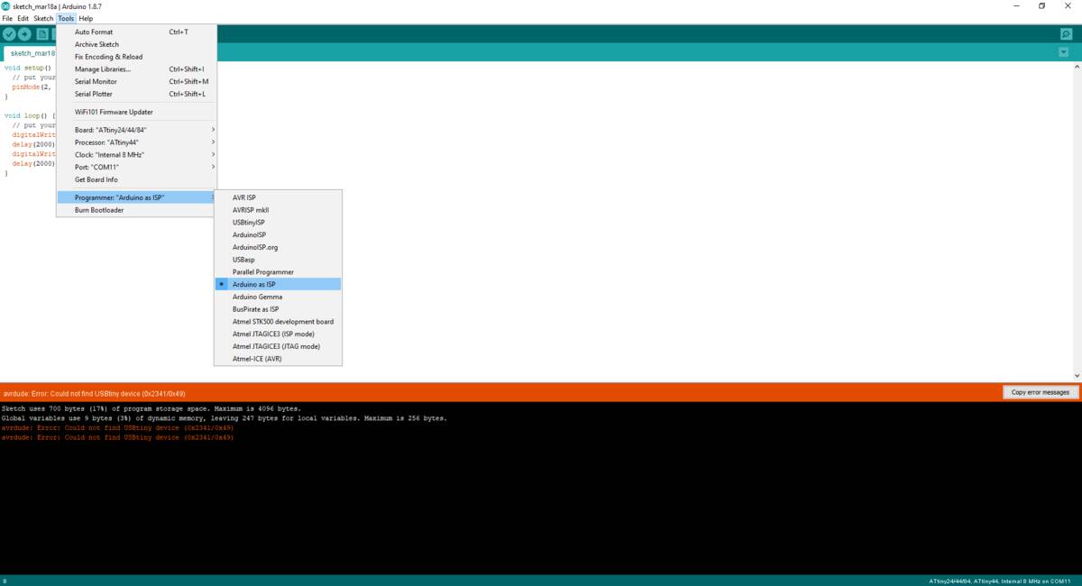
The setting in the Arduino IDE
After doing so and when trying to upload you will get some error like avrdude: stk500_getparm(): (a) protocol error, ... I found that the reason for this was that I didn't add a capacitor between the Arduino GND and Reset pin. Without the capacitor, the arduino will reset itself when trying to flash the attiny. So just add a 10uF capacitor between both and you're good to go.

The Arduino wired up with the capacitor
Finally you get the right feedback from the Arduino IDE:

The Arduino IDE successful
Finally I wrote a program to use the button, which just uses a variable for the old state of the button to decide when the button has a change of state:
// constants won't change. They're used here to set pin numbers:
const int buttonPin = 7;     // the number of the pushbutton pin
const int ledPin =  2;      // the number of the LED pin

// variables will change:
int buttonState = 0;         // variable for reading the pushbutton status
int lastButtonState = 0;

void setup() {
  // initialize the LED pin as an output:
  pinMode(ledPin, OUTPUT);
  // initialize the pushbutton pin as an input:
  pinMode(buttonPin, INPUT);
}

void loop() {
  // read the state of the pushbutton value:
  buttonState = digitalRead(buttonPin);

  // check if the pushbutton is pressed. If it is, the buttonState is HIGH:
  if (buttonState != lastButtonState) {
    if (buttonState == HIGH){
      digitalWrite(ledPin, HIGH);
    }
    else {
      digitalWrite(ledPin, LOW);
    }

  }
  lastButtonState = buttonState;
}
With this program the board will turn off the led when the button is pressed:
The board with working button
Conclusion
While the c code is harder to write the arduino code makes it much easier and more readable. The only problem with that is that the c code is compiled to a size of about 100byte while the compiled arduino code is more than six times as large (for the blinking program). For this small program it doesn't matter, but for bigger programs you will run out of the 4kbyte of storage of the attiny very quickly. So it is definitely important to know how to write programs in c for the attiny.
Files
Here you can download the files created during this week:
The blink c file (usbtiny)
The corresponding Makefile (usbtiny)
The blink arduino file
The button arduino file