Group Assignment:
● compare the performance and development workflows for other architectures. Individual Assignments:
● Read a microcontroller datasheet.
● Program your board to do something, with as many different programming languages and programming environments as possible.
ATtiny44 Datasheet
The firs assignment of this week was to read a microcontroller datasheet.
For this week's assignment, I was going to use the board that I made in week 6 using Attiny44 for programming, so I decided to read the
same microcontroller's datasheet.
Attiny44 is a low power AVR® 8-Bit microcontroller. Some of the microcontroller features are listed below:
- 4K bytes of flash programming memory (10,000 Write/Erase Cycles).
- 256 bytes of EEPROM (100,000 Write/Erase Cycles).
- Twelve programmable I/O lines.
- Pin change interrupt on 12 pins.
- One 8-Bit and one 16-Bit Timer/Counter.
- Eight 10-bit ADC (PA0-7).
- 0 – 20 MHz @ 4.5 – 5.5V.
- 8 MHz internal calibrated RC oscillator.
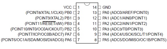
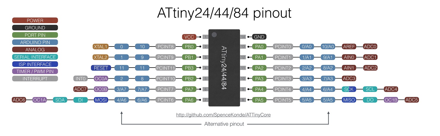
Figure 1. Pinout of ATtiny44.
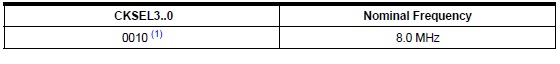
In the Clock Sources section, you can find information to configure the clock of the system.
For instance, if you want to use the internal calibrated 8 MHz RC oscillator, the
CKSEL fuse bits must be set as shown in Fig. 2. The chip was configured with internal oscillator selected by default.
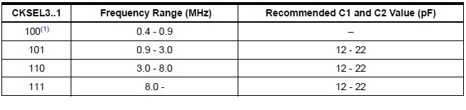
Fig. 3 shows the CKSEL configuration for external Crystal Oscillator / Ceramic Resonator. The
echo board that I made in week 6 has a 20 MHz ceramic resonator,
So the CKSEL3..1 for its microcontroller has to be 111.
Figure 3. Crystal oscillator operating modes.
I also took a look at some other sections of datasheet such as Ports as General Digital I/O, Register description, etc.
Atmel Studio
I wanted to program the board from week 6, in the way that by pressing the push button, LED starts to blink.
The number of blinks shows how many times the
the button was pressed. For example, if you press the push button once the LED blinks once,
and by pushing the button for the second time it blinks twice, and so on.
On the board, the LED is connected to PB2 and the push button is connected to PA7.
I explain how I write the needed code and programmed the ATtiny44 at Atmel Studio 7 in the following.
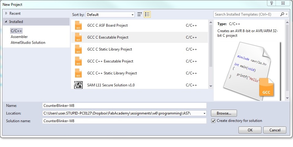
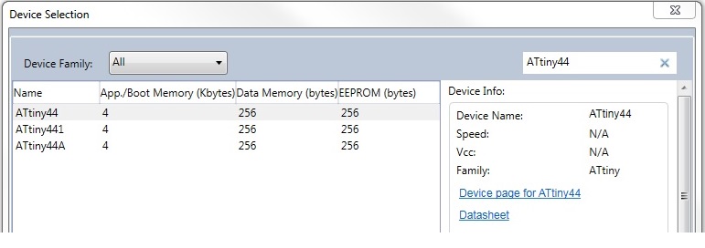
First, you need to create a new project with Atmel Studio (Fig. 4) and select ATtiny 44 as the device (Fig. 5).
Figure 4. Creating a New Project.
Figure 5. Selecting the microcontroller.
The next thing to do is to set the LED pin (PB2) as an output. In the section Ports as General Digital I/O of the datasheet,
you can find all the information needed to do do the task.
Each port pin consists of three register bits: DDxn, PORTxn, and PINxn:
- DDxn: The DDxn bit in the DDRx Register selects the direction of this pin. If DDxn is set to logic one,
Pxn is configured as an output pin. If DDxn is set to logic zero, Pxn is configured as an input pin.
- PORTxn: If PORTxn is set to logic one, when the pin is configured as an input pin, the pull-up resistor is
activated. To switch the pull-up resistor off, PORTxn has to be set to logic zero or the pin has to be configured as an output pin.
If PORTxn is set to logic one, when the pin is configured as an output pin, the port pin is driven
high (one). If it is set to logic zero , the port pin is driven low (zero).
- PINxn: The port pin can be read through the PINxn Register bit.
There is a very useful series of tutorial videos on YouTube, published by Atmel. I could
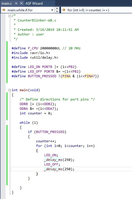
find well-explained example codes from there. Fig. 6 shows my code in Atmel Studio.
Figure 6. Programming in Atmel Studio.
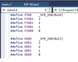
The ‘DDB2’ value is defined 2, to make the code more understandable. To see all the definitions,
right click on DDB2 in the code and select Goto Implementation (Fig. 7).
Figure 7. The definitions.
To compile the code and build a .hex file, go to Build > Build Solution.
To burn the .hex file on the microcontroller, use avrdude
(as explained in week 6).
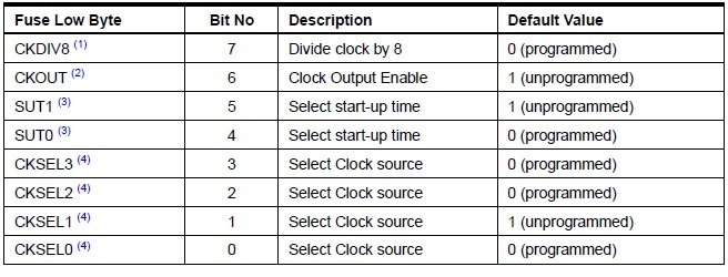
First, I set lfuse to 0x5E for 20 MHz xtal from the command line: avrdude -p t44 usb -c usbtiny -U lfuse:w:0x5E:m
Fig. 8 shows the description of each bit of the Fuse Low Byte.
Figure 8. Fuse low byte description.
Then, run the following command to program the board's microcontroller's flash memory with the contents of the .hex file (Fig. 8). avrdude -c usbtiny -p t44 -v -v -v -U flash:w:CounterBlinker-W8.hex:i
Arduino IDE
I wrote the same code that I had written in Atmel Studio, in the Arduino IDE. To add the ATtiny44 board in Arduino IDE, I followed these steps:
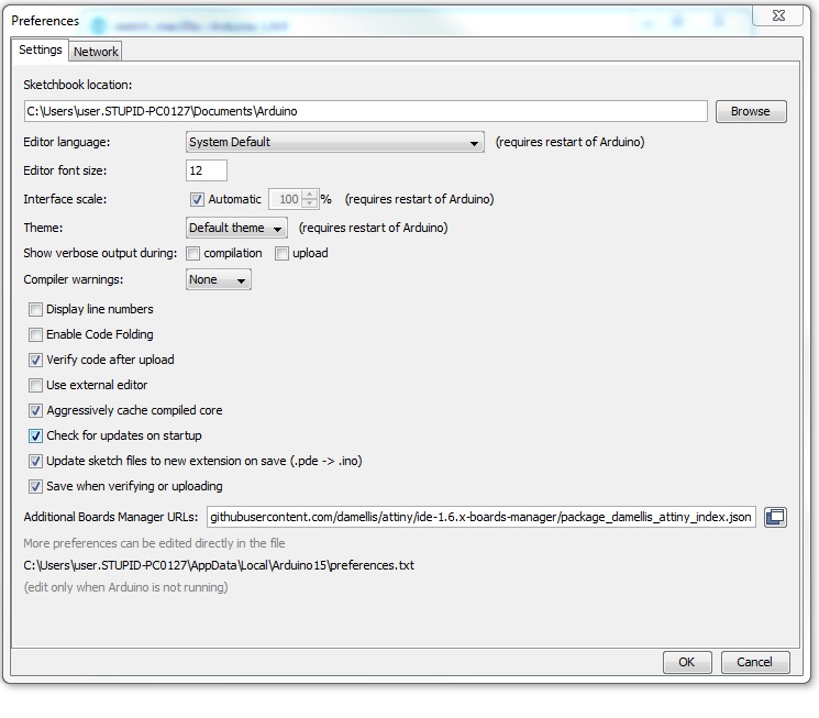
1. Open the Arduino IDE and add the following URL to File > Preferences > Additional Boards Manager URLs (Fig. 9):
https://raw.githubusercontent.com/damellis/attiny/ide-1.6.x-boards-manager/package_damellis_attiny_index.json
Figure 9. Additional Board Manager.
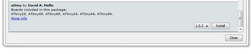
2. Then, go to Tools > Board:xxx > Boards Manager and install attiny by David A.Mellis board (Fig. 10).
Figure 10. Installing ATTiny.
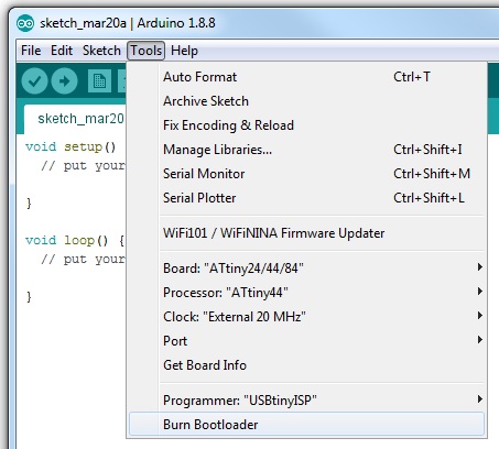
3. Now, you should be able to find ATtiny24/44/84 from Tools > Board:xxx.
Select this board and correct the setting (e.g. Clock, programmer). Then, burn the bootloader (Fig. 11).
Remember to connect your USBTinyISP (or any other type that you are using) programmer for burning the bootloader.
Figure 11. Burning the bootloader.
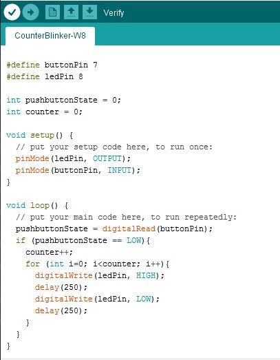
Fig. 12 shows my code written in the Arduino IDE. In my board, the LED was connected to PB2, which in ATtiny44 is pin number 8 (Arduino pin number),
and push button to the PA7, which is pin number 7 (Fig. 13). So, in the code I
defined two variable to map these two pins.
Figure 12. My code written in the Arduino ID
Figure 13. ATTiny pinout.
Group Work
The group assignment for this week was to compare the performance and development workflows for other embedded architectures.
This task was done together with all the members of the Fab Academy Oulu.
The detailed reports can be found in Jobin’s and Marjo’s weekly assignment pages, but here is a short summary:
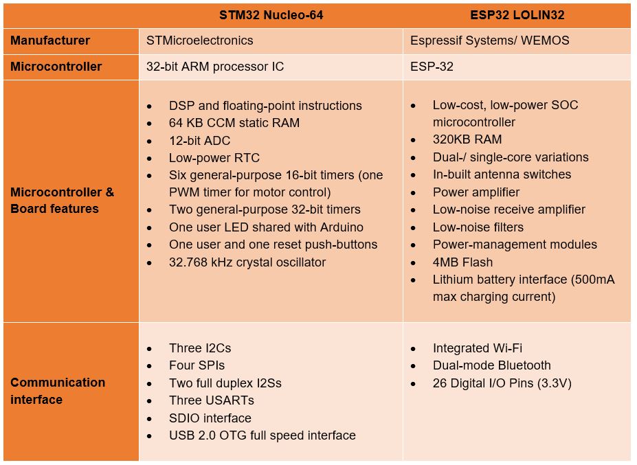
We tested STM32 Nucleo-64 development board with STM32F401RE MCU and ESP32 LOLIN32 development board. We used Arduino IDE for programming the processors.
The table below shows the most important features of each of the programming boards:
Figure 14. Features of the programming boards.
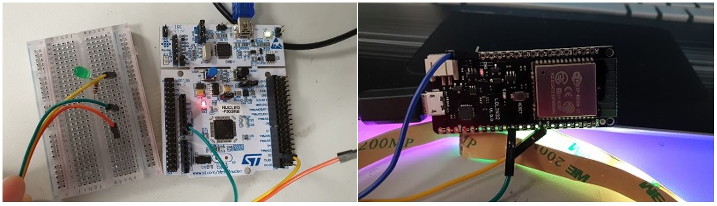
An LED-blinking test was programmed on both development boards. For both cases, LED pin connection was done based on the pin number and the blinking test was run.
The LED-blinking code can be found here.
The Video for the test with STM32 Nucleo-64 can be found from here.
Figure 15. a) STM32 Nucleo-64 and b) ESP32 LOLIN32 in the LED-blinking test (the photos were taken from Marjo’s page).
For a simple test, like the above-mentioned one, both of the boards performed well with no challenge to the hardware,
although programmed with a high-level code like Arduino.
Reflection
I had experience with embedded programming, so, this week was not new for me. The only problem hat I encountered was that after programming the microcontroller
, the LED was blinking 8 times slower than expected. The problem was caused by bad fuse bit (CKDIV8 bit) programming.