Week's Assignments
Group Assignment:
● test runout, alignment, speeds, feeds, and toolpaths for your machine.
Individual Assignments:
● make (design+mill+assemble) something big
Group Work
The group assignment for this week was done in a single group consisting of all the Oulu branch students.
Eino Antikainen (FabAcademy 2017 graduate) gave a comprehensive
tutorial on the subject, including: creating a file, setting the tools paths and exporting it for milling, using CNC Router and safety issues.
The process of CAM settings and making the .nc file is described in following. Here, I concentrate on operating the CNC Router machine. Some of the pictures and measurements for the group work are taken from
Jobin's and
Michael's pages.
Since the milling bit, which was already installed on the machine, was not a 8mm flat one, the first step was to replace it with the right one (Figure 1).
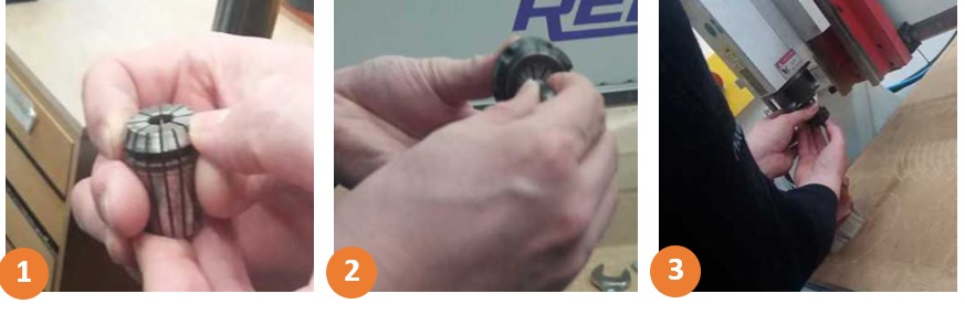 Figure 1.
 Replacing the milling bit.
After replacing the milling bit, we put the board on the machine platform and screwed it tightly (Figure 2). This was done to make sure that it will not move during the milling process.
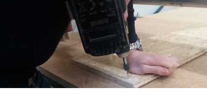 Figure 2.
 Screwing the board.
The next step was to set the X, Y and Z origins. To accomplish that, we powered on the machine. Figure 3 shows the buttons on the machine. Then, we started the NcStudio software from a computer that
was located next to the machine (Figure 3-1). The CNC router machine was controlled by a computer located next to the machine (figure 4).
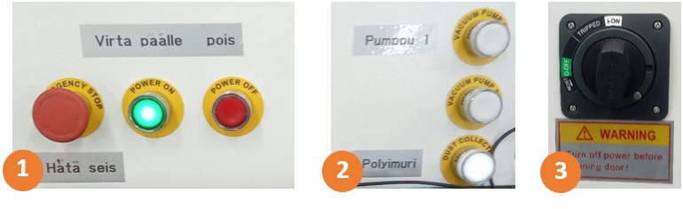 Figure 3.
 1-Machine on/off switches and emergency button
2-Vacuum for the sacrificial board and dust collector for the drill 3-Machine power.
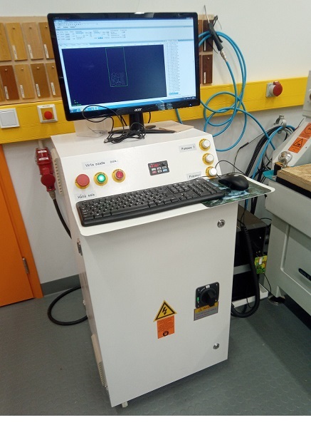 Figure 4.
 CNC Router Machine.
The header can be moved either through the software (figure 5-1) or hand-held controller (figure 5-2). For the X and Y axes, just move the header to the desired position (be careful with the screws), and then use the W.Coord
button for the X and Y in the software to set the origin. The same procedure can be performed for the Z axis. There is also an automatic calibration method for the Z axis. In this approach, you have to put the
mobile calibrator just underneath the milling bit (Figure 6). Next, start the calibration process from Operation > Mobile Calibration... in the software. The milling bit will move down until it touches
the metal surface of the mobile calibrator, and it will automatically set the origin for the Z axis to that point.
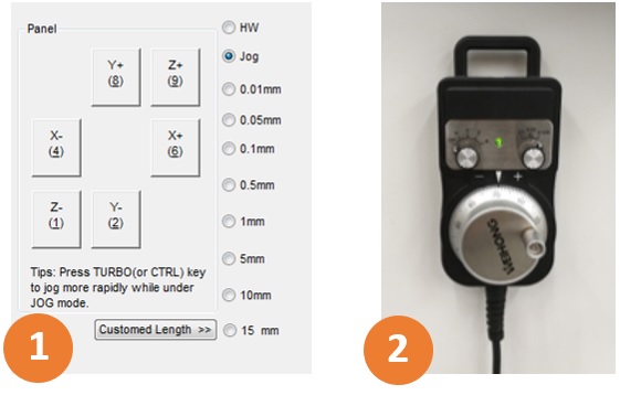 Figure 5.
 1-moving the header from the software
2-hand-held controller.
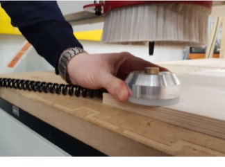 Figure 6.
 Adjusting the mobile calibrator.
After setting the origin, we loaded the .nc file, from File > open and load. Then, we clicked on simulation button to see if everything is OK. Next, the feedrate and Spindle values were reduced
respectively to 80% and 88% of their maximum values (figure 7), in order to increase the quality of the milling process. Finally, we pressed the play button to start the milling process.
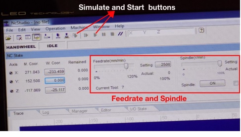 Figure 7.
 Setting Feedrate and Spindle.
Figure 8 shows some images of Eino’s designed test file, cut board and measurements for the group work.
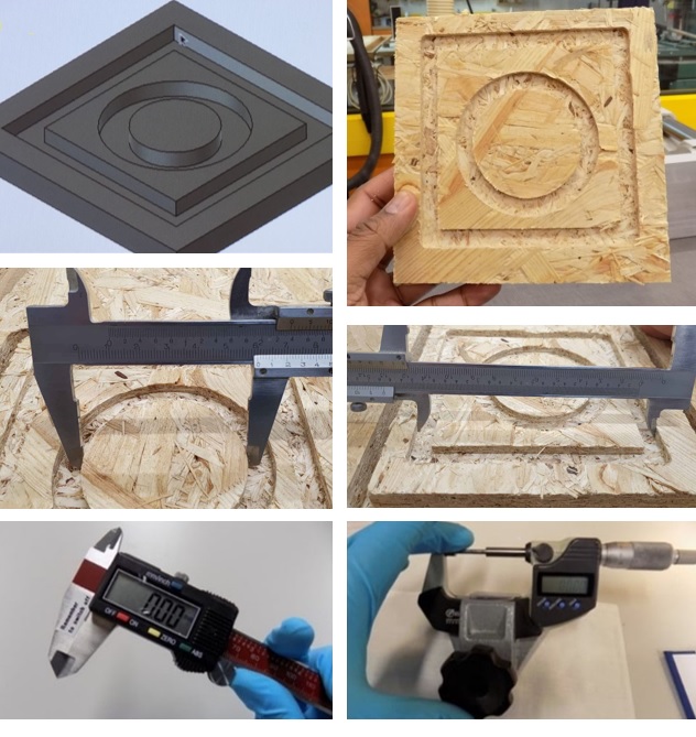 Figure 8.
 Designed test file, cut board and measurements.
Table 1 shows the detailed measurements of the milled design. It can be seen from the table that the average milling length for the two squares is 20.14 mm, while the average milling length for the two circles is 20.16 mm.
Both values are quite close to their corresponding dimensions in the 3D design.
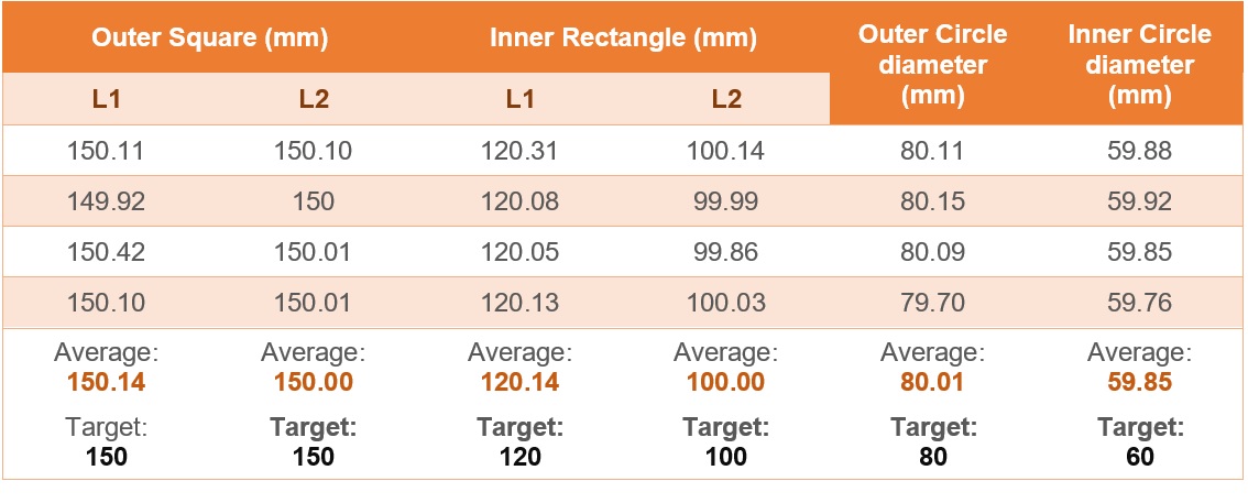 Table 1.
 Measurement results.
In addition, the engraved area from the square, and circular engraved thickness were measured before and after milling using a digital screw gauge. The results can be found in table 2.
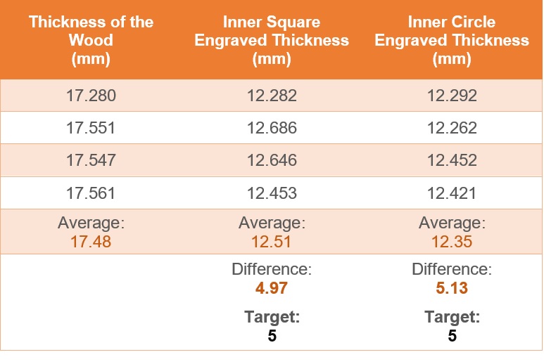 Table 2.
 Engraved thickness measurement results.
Designing a Big 3D Model
For this week's assignment, we had to design something big to be built using the CNC router machine in our Fab Lab. The material available for us was Oriented Standard Board
of 11 millimeter thickness. I decided to design a baby elephant rocker as a present for my friend's kid. I found an elephant rocker design here, so I followed its design
to make my own. Figure 9 a raster image of different parts of the designed elephant.
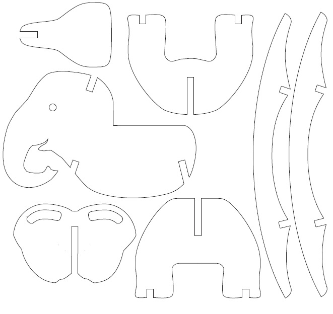 Figure 9.
 Raster image of different parts of the designed elephant.
The original design was drawn on wood and then cut the pieces using a band-saw. I tried to manipulate design to make them suitable for my 3D design. Here is a summary the steps I followed:
1. The quality of the image was poor (figure 10-2), so I manipulated its the Brightness and Contrast properties using Gimp software to make it better (figure 10-2).
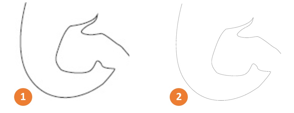 Figure 10.
 Modifying the Brightness and Contrast of the image.
2.
Vectorizing the image using Inkscape.
3 . I imported the vectorized image (.svg) to Fusion 360. To do that, click
Insert and Next
Insert SVG (figure 11-1). Then browse the .svg file from the computer, and finally
select the plane you want to import the .svg on (in our case was XY plane (figure 11-2)). Now, a window pops up that lets you scale the the design, flip it, etc. (figure 11-3).
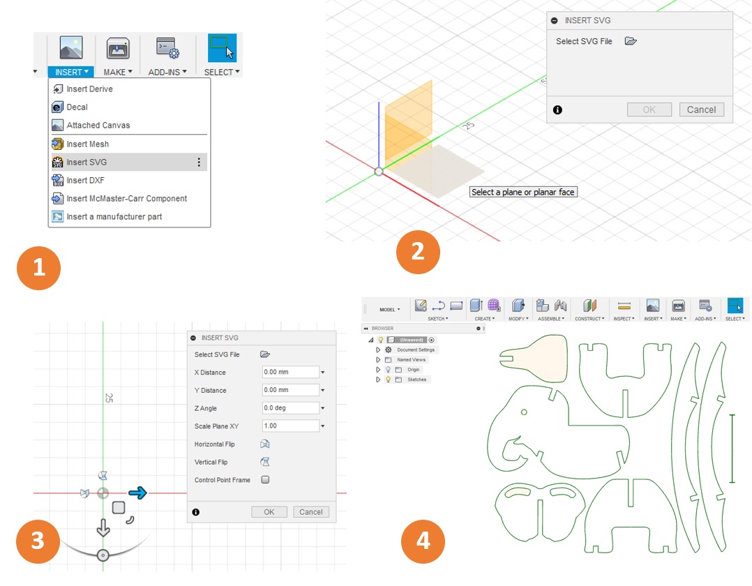 Figure 11.
 Importing the .svg file to Fusion 360.
4. All the outlines are green, it means They are fixed and we can not move them. When you import a .svg file, it has fixed geometry by default. To unfix the geometry, select all the parts,
then right click and toggle Fix/UnFix (the outlines must turn blue).
5. When I zoomed into the sketches, it revealed that the vectorized images have two separate lines, one related to the outer border of raster image and one for inner part (figure 12). So, I deleted one of them from all
the different parts of the Rocking-Elephant.
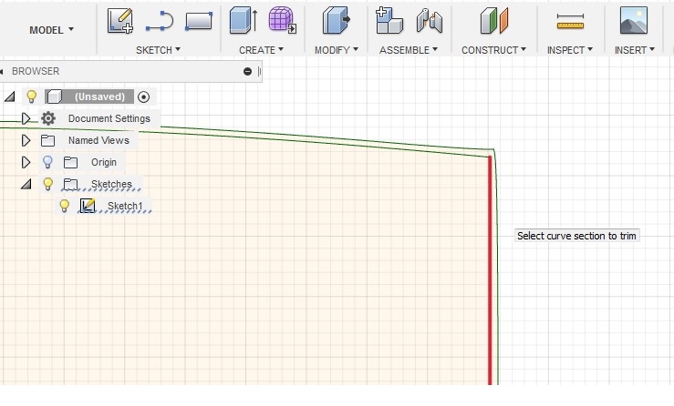 Figure 12.
 Deleting extra lines from the sketches.
6. Some of the connected sketch lines did not create a profile. So, I zoomed in to the maximum and went around all the sketches to find and fix any existing separations between the lines (figure 13).
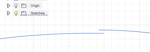 Figure 13.
 Line separations in the sketches.
7. As mentioned, the material that I was going to use was Oriented Standard Board with 11mm thickness, so I modified the fit joints according to thickness (figure 14). I made the slot 10mm to be sure that the connections will be tight enough. However, 10mm was
a bit small and I had to file some of the slots to make them wider (0.5mm narrower than the thickness would be a better size for the slots).
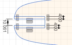 Figure 14.
 Modifying the fit joints.
8. To extrude the sketches, select
Create > Extrude, click the surfaces and then drag it up and set the height to desired value (Figure 15).
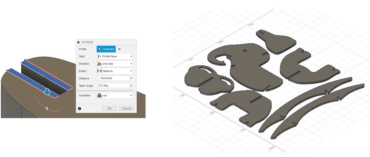 Figure 15.
 Extrude the sketches.
CAM Settings
To create the tool paths (G-codes) for the CNC router, Eino Antikainen instructed us to download the CAM processor file and the setting files with values for different milling bits available in our Fab Lab.
from the Fab Lab Oulu Wiki site and add them to Fusion.
To make the G-codes in Fusion 360, first I select MANUFACTURE environment from MODEL > MANUFACTURE. Here are the steps I took to make the CAM settings ready:
Setup
1. Open
SETUP > New Setup. Next, check that the
Operation Type is
'Milling'.
2. To set the work coordinates, set the
Origin to
'Stock box point'. The
Stock is a piece of material that the finished part will be cut out of. A box should appear around
the parts. click on the
Stock Point and select one of the stock points. I selected one of the bottom corner points (figure 16). Check that the selected Z axis of the actual board, that will be milled, is the vertical axis of the CNC router.
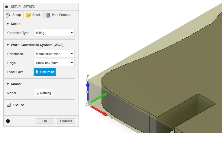 Figure 16.
 Setting the Work coordinates.
3. Click on the
Stock tab and change all the offset values to 0mm (figure 17).
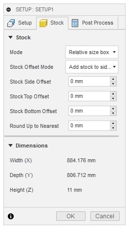 Figure 17.
 Setting the Offset Values.
2D Pocket Settings
1. Open
2D > 2D Pocket.
2. I was going to use a 8mm Flat milling bit. To select the correct milling bit, first click on the
Select... button under the
Tool tab. Then, choose the 8mm Flat milling bit from
the library (suggested by
Eino to be downloaded (figure 18)).
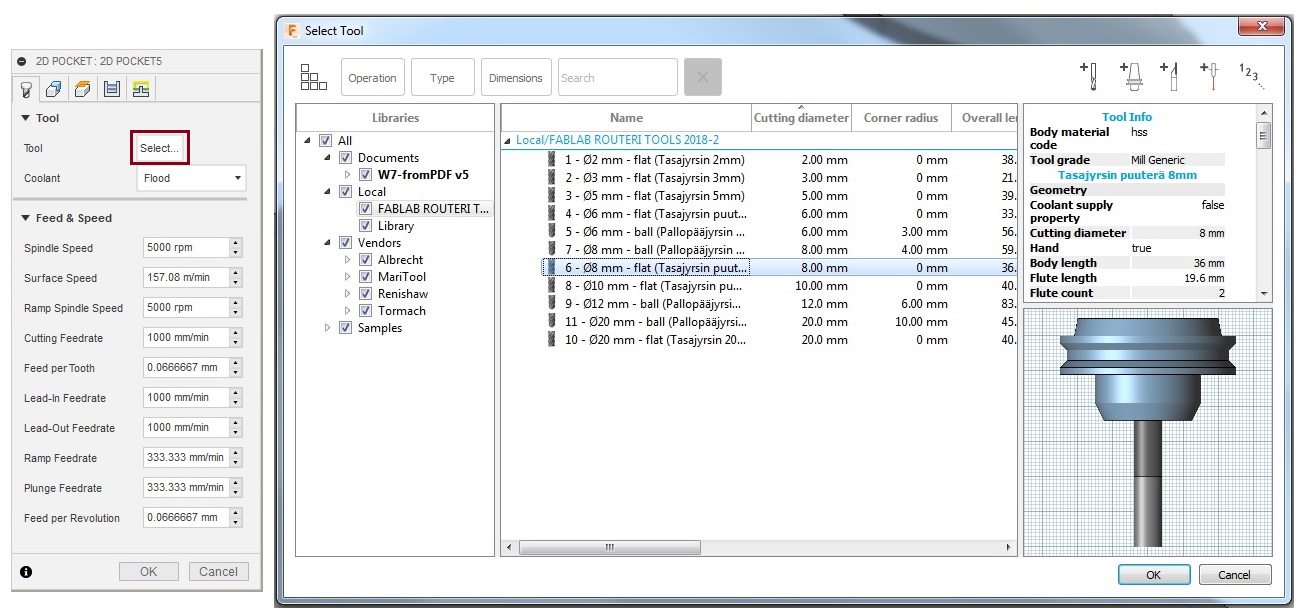 Figure 19.
 Setting the milling bit.
3. Under
Geometry click on the
Pocket Selections and then, select the areas where you want to make pockets (figure 20).
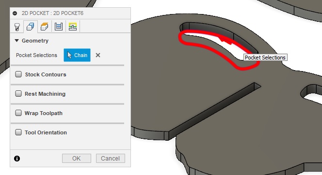 Figure 19.
 Pocket Selection.
4. Set the top and bottom heights, in the
Heights tab (figure 20).
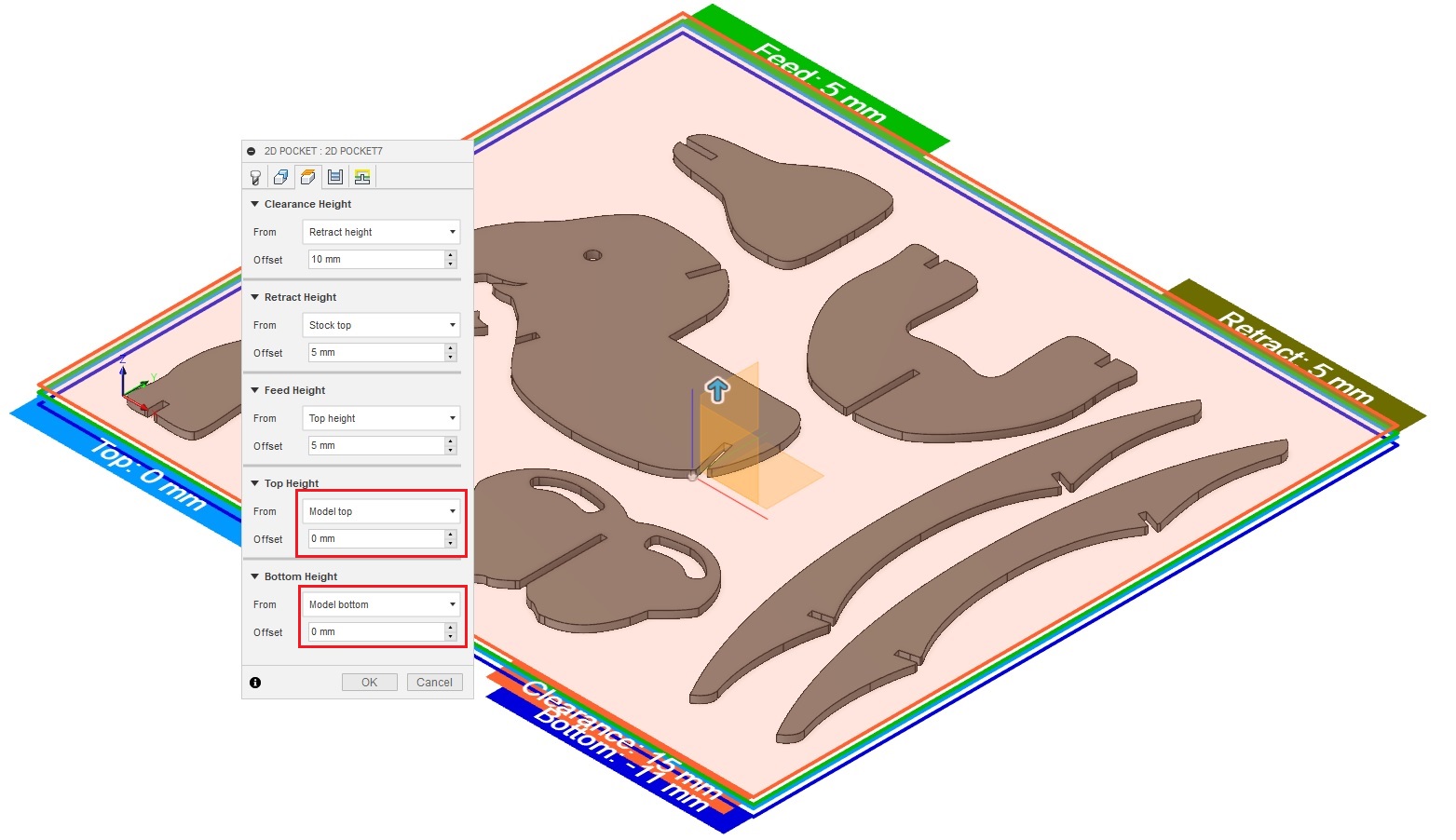 Figure 20.
 Setting the top and bottom heights.
5. In the
Passes tab, I set
Maximum Roughing Stepdown to 3mm and
Finishing Stepdown to 0.2mm (figure 21-1). And, in the
Linking , deselect
Leads & Transitions (figure 21-2).
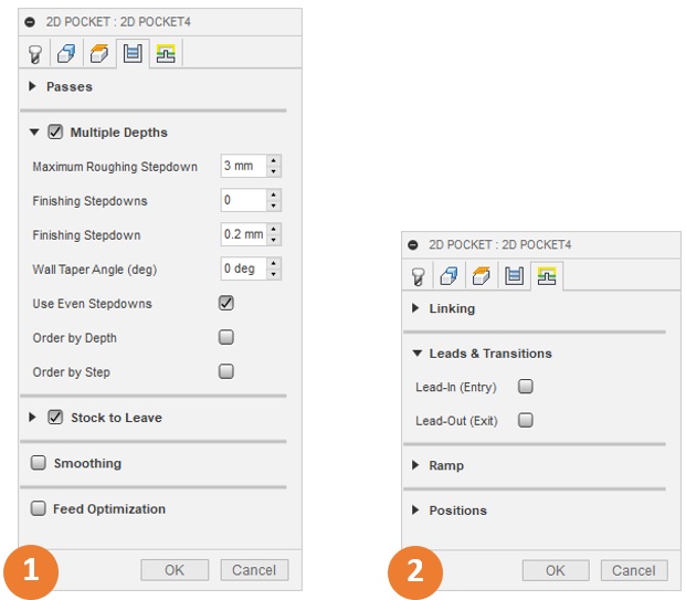 Figure 21.
 Passes and linking settings.
2D Contour Settings
The contour setting is done from
2D > 2D Contour. The process was more or less the same as what we did for 2D pockets settings. Figure 22 shows the different tabs for the contour setting.
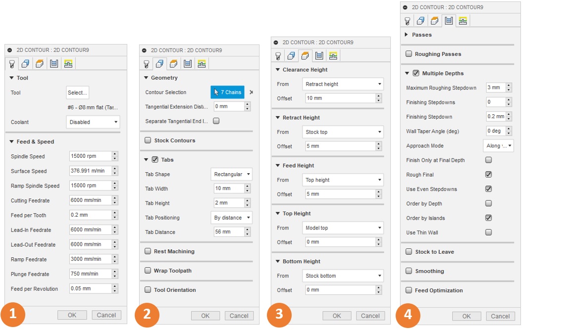 Figure 22.
 2D Contour Settings.
As figure 22-2 shows, I added tabs to keep the parts in their place and prevent moving during the milling job. I set the tabs' width to 10mm and their height to 2mm. The tabs can be seen in figure 23.
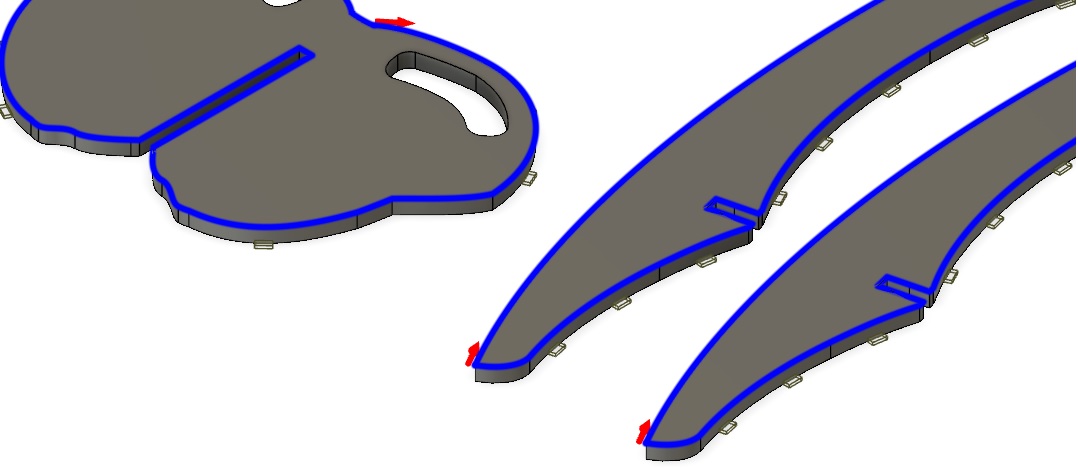 Figure 23.
 Adding tabs.
Simulation
I simulated the tool paths in Fusion 360 before exporting the .nc file for the CNC route machine, just to make sure that everything works as expected. To start the simulation, click on the simulation icon
(

) and then, click on the play icon (

) at the bottom of the page.
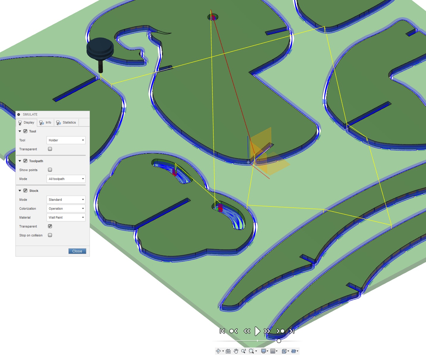 Figure 24.
 Simulating the tool paths and stock material removal.
After simulation and checking that the everything is fine, I generated the .nc file from
ACtion > Post Process. Our Fab Lab instructors provided us with the Post Configuration file that is used to
translate the Fusion 360 dialect into the dialect that the machine understands.
Cutting
After Simulating the tool paths and exporting the .nc file, I repeated the same process that I described in the group work to mil the parts using the CNC router machine. I reduced the Spindle speed to 70% and
Feedrate to 81% of their total values (figure 25), as Eino recommended. Figure 26 shows some pictures of the milling process. I used paper a cutter to cut the tabs (figure 27). After some sanding and filing some of the
parts, I managed to mount all the part together (figure 28).
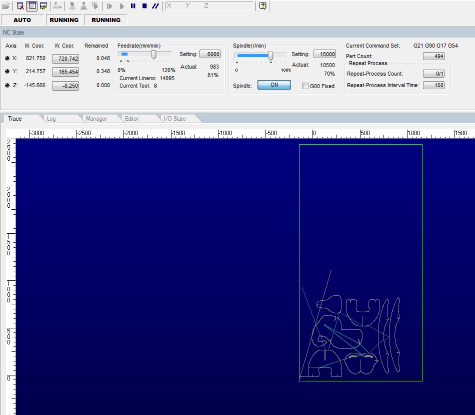 Figure 25.
 Setting the Spindle speed and Feedrate.
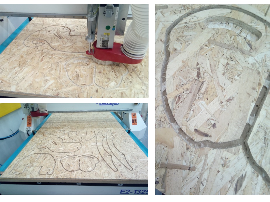 Figure 26.
 Milling process.
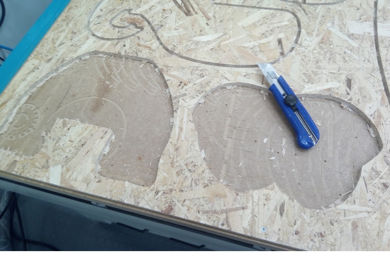 Figure 27.
 Cutting the tabs.
A rounded CNC bit cannot reach all the way into an inside angle (figure 28-1), which causes problems in most of the joinery types. One common approach to fix
the problem is using dog-bone. Figure 28-2,3 shows two types of dog-bones that can be used for press-fit joints.
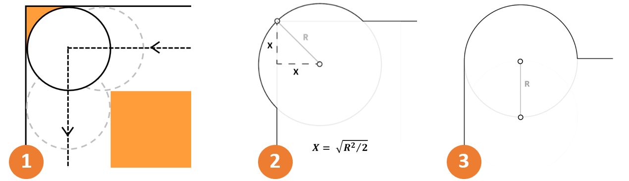 Figure 28.
 Dog-bones.
The drawback of using dog-bones is that they create unwanted holes at the joints. To prevent these holes, I did not use dog-bones,
instead filed the inside angles of the joints to make them 90 degree. Then with a little hammering I could fit pieces together. Figure 29 show the assembled elephant rocker.
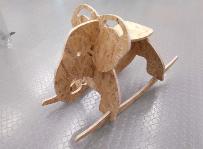 Figure 29.
 Final result.
As mentioned, I did not add dog-bones to my design, but the process is simple in Fusion 360. Here is a YouTube tutorial video, that
escribes how to make dog-bones in Fusion 360. There is an add-in for Fusion 360, created by Casey Roger,
that allows adding dog-bones to the design in an automated way. Here is a summary of the steps that should be followed:
1- Download the add-in.
2- Unzip it and drop it in %AppData%\ Autodesk\Autodesk Fusion 360\API\AddIns .
3- When you start Fusion 360, it should be already added there (figure 30). If not, you can add it manually from ADD-INS menu  .
.
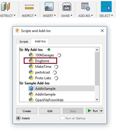 Figure 30.
 Dogbone add-in in Fusion 360.
4- Select the Dogbone and press the Run button (or double click). It will add an extra icon to the Fusion’s toolbar (figure 31).
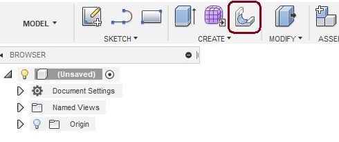 Figure 31.
 Dogbone icon in toolbar.
5- Select the edge ( or edges) you want to create the dog-bone on. Next, click on  and set the tool diameter according to the mill bit (figure 32)
that you are going to use. Then click OK.
and set the tool diameter according to the mill bit (figure 32)
that you are going to use. Then click OK.
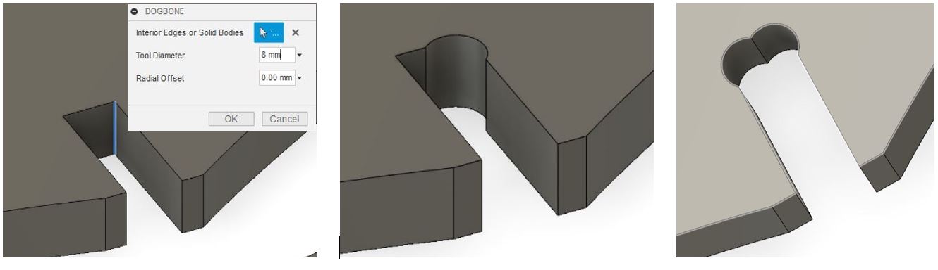 Figure 32.
 Making dog-bones at edges.
Reflection
This was my first time I had used a CNC router Machine. So I learned about how to prepare a 3D model design to be milled (CAM settings and so on), and how
to work with the CNC router. But I still need to learn and practice a lot.