Group Assignment:
● Test the design rules for your 3D printer(s). Individual Assignments:
● Design and 3D print an object (small, few cm3, limited by printer time)
that could not be made subtractively
● 3D scan an object (and optionally print it)
Group Work
Alok, Michael and I worked
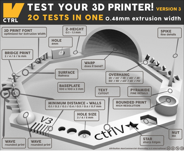
as a group to test the design rules for three different 3D printers existing in our FabLab. We used Test your 3D printer file (Figure 1), as
the test design for all the 3D printers that were tested.
Figure 1. Test your 3D printer.
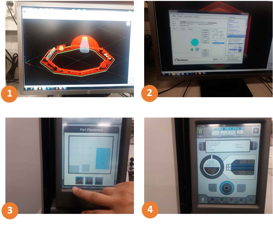
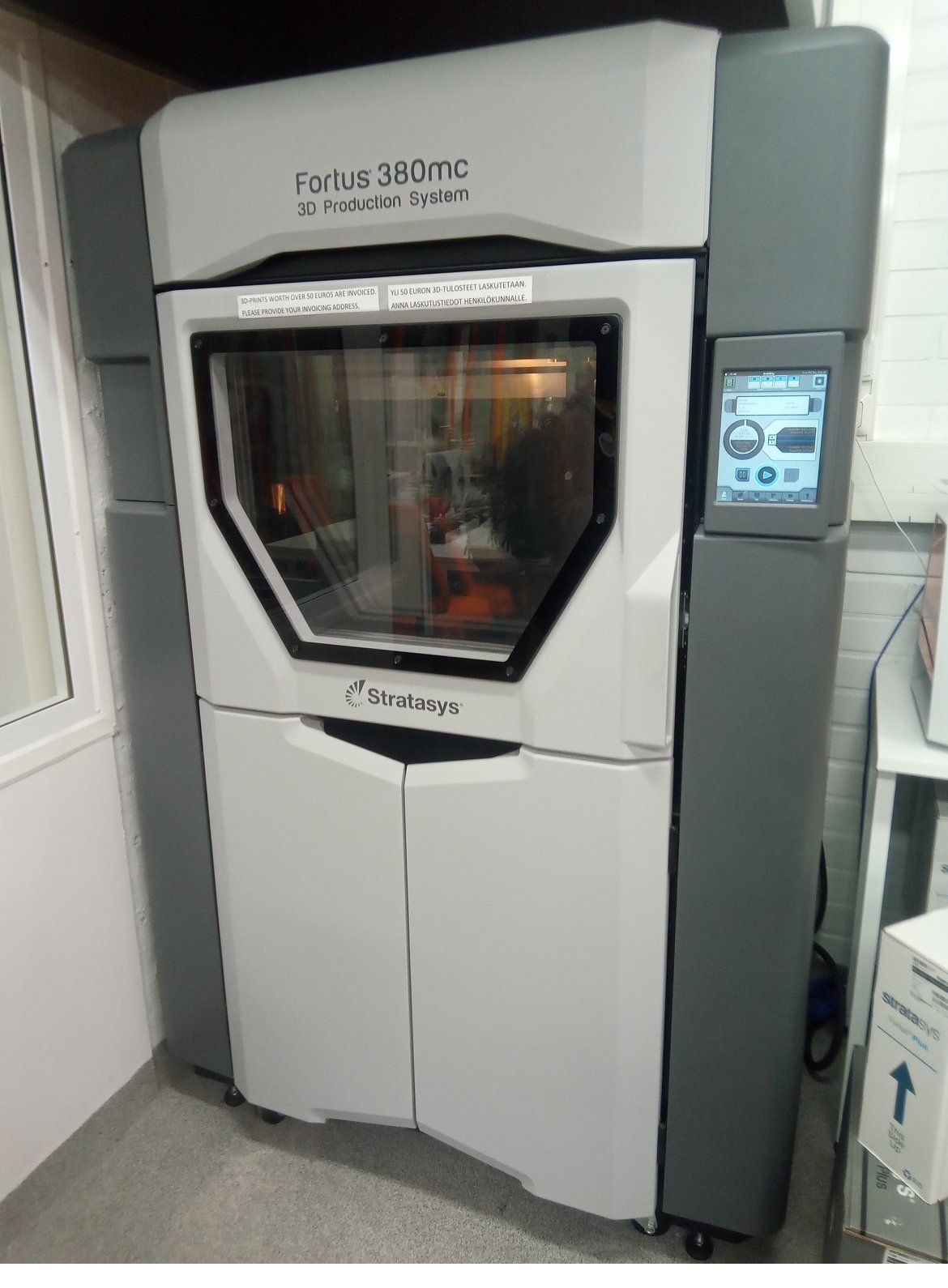
1. Stratasys Fortus 380mc 3D
Stratasys Fortus uses additive manufacturing process which print the object layer by layer from bottom to top, based on Fused Deposition Modeling (FDM) technology. It uses ABS (Acrylonitrile Butadiene Styrene) material,
and the maximum build size for the machine is 355x305x305 mm.
in order to print the test piece, first we opened the .stl file in Insight. A comprehensive tutorial for the Insight software can be found
here. Next we set the Part interior style to "Sparse",
Visible surface style to "Enhanced" and Support style to "Smart" properties from the main window (Figure 2). Then We clicked on Finish button and after that Built the job button.
Figure 2. Slicer Settings.
Before starting the printing process, we placed a base sheet on top of the 3d printer's work base. We closed the door and waited for a while until the sheet get heated and flattened. Next, print job was selected from the printing queue which is visible in the Stratasys’ control panel. Then the
placement of the printing part was adjusted through the 3D printer's touch screen GUI (figure 3.3). The actual printing time also can be find on the printer's screen. Finally we pressed Play button to start the printing process (figure 3.4).
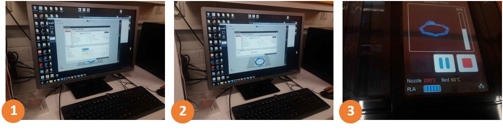
Sindoh works based on Fused Filament Fabrication (FFF) technology. It is a 3D printing process that uses a continuous filament of a thermoplastic material. This 3D printer uses the same material for both model and support.
therefore the designs that they need to use support material, like what I have designed for my individual assignment, cannot be made using this machine.
Figure 4. 1-Support settings: none. 2-Bed adhesion settings: none. 3-Feedback in the display.
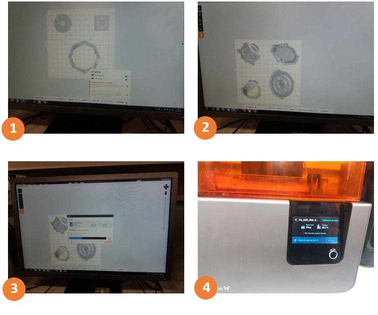
Formlabs is based on Stereolithography (also known as optical fabrication, photo-solidification, or resin printing) technology. It is an additive manufacturing process where a laser beam builds up a model layer by layer from liquid
polymer that hardens on contact with the laser light. We printed the test piece using the Formlabs in our Fablab. After printing, the model was first cleaned in Isopropyl alcohol, and then cured in 405 nm light. As it uses Class 1 laser and toxic resin, precautions should be taken
to use it safely. The safety guidelines can be found here.
Figure 5. 1-Placing the parts and rotating them by45 degrees as software recomands.
2-All the parts. 3-Sending the part to the printer. 3-Feedback in the display.
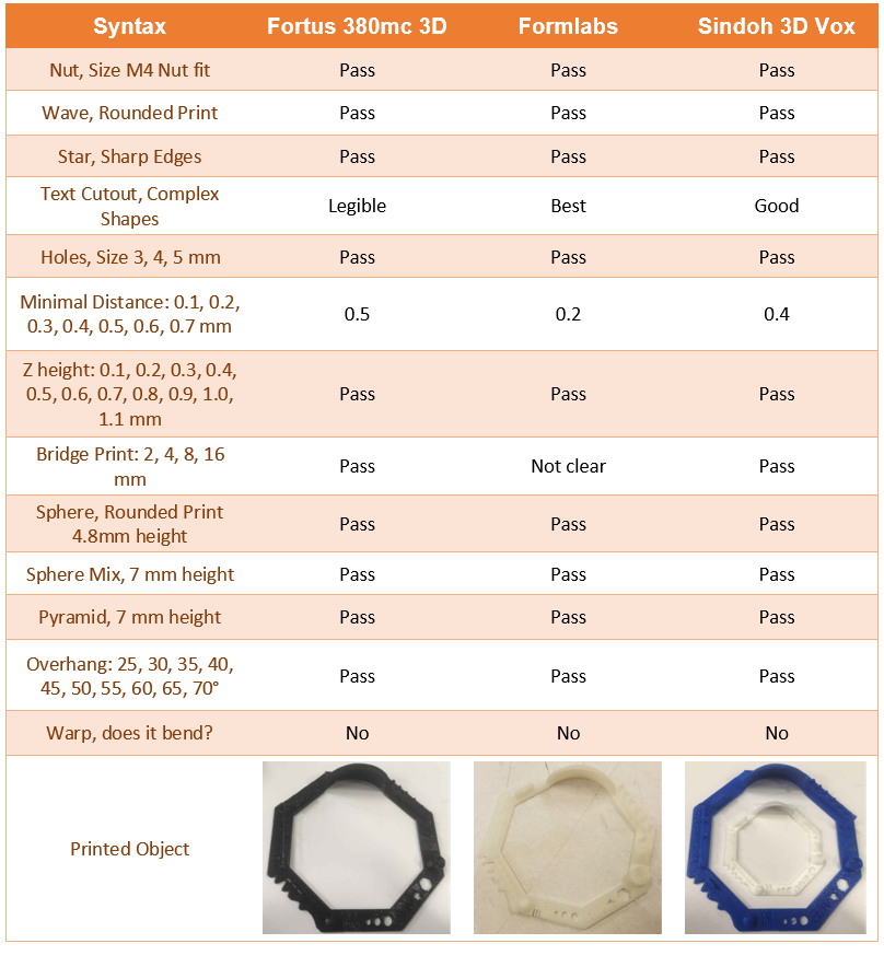
Table 1. Printing Results.
Among these three printers that we tested, the Formelabs was able to fabricate the object more accurately. But in the Other side Fortus 380mc can fabricate larger objects. Besides, the printing process with this printer is simpler because,
printed object does not need to be cleaned in Isopropyl alcohol and be cured in 405 nm light. The Accuracy of Sindoh was slightly better than Fortus 380mc, but the downside of the Sindoh is that it does not use support materials.
3D Design
For this week, we were supposed to 3D-print an additive model that could not be made subtractively
(by milling process, CNC, e.g.). I had a 3D model that I had designed as the assignment for the COMPUTER
AIDED DESIGN week. It is a part of the cord reel, which is going to be used in my final project. But since
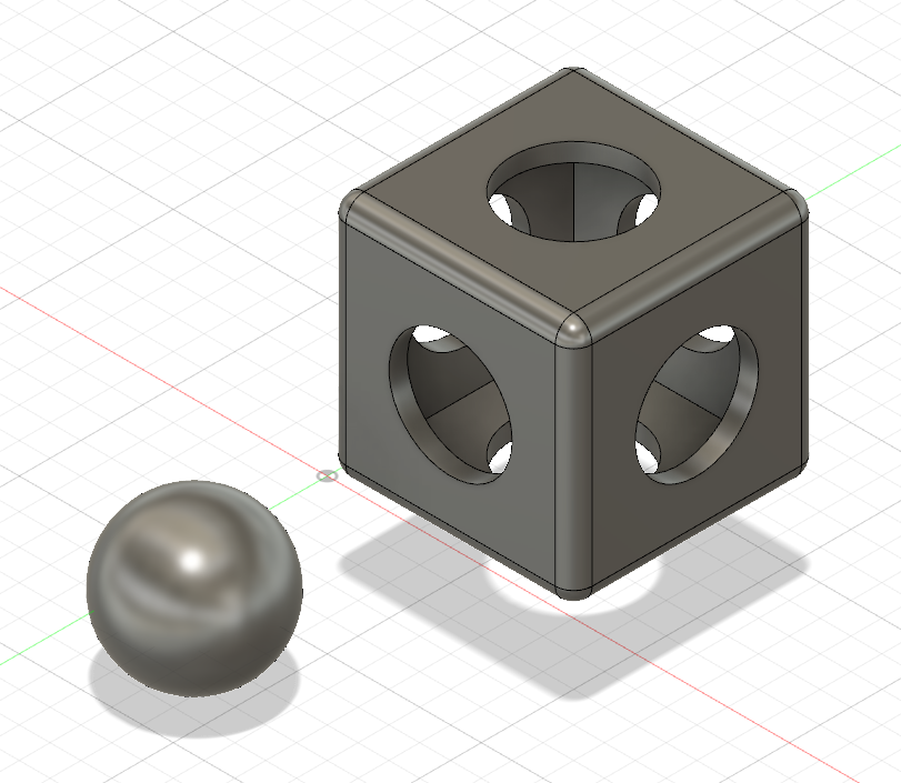
that design could be built subtractively, I designed another 3D model (a ball trapped inside a cube) for this week's assignment.
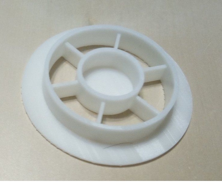
I 3D-printed both of the above-mentioned designs. For the cord reel design, I utilized FormLabs Form 2 printer, which uses stereolithography technique. The results can be
seen in figure 6.
Figure 6. FormLabs Form 2, 3D printing result
Among these three printers that we tested, the Formelabs was able to fabricate the object more accurately. But, on the other hand, Fortus 380mc can fabricate larger objects.
Besides, the printing process with this printer is simpler, because the printed object does not need to be cleaned in Isopropyl alcohol and cured in 405 nm light.
The accuracy of Sindoh was slightly better than Fortus 380mc, but the downside of the Sindoh is that it does not use support materials.
Here's a brief explanation of the steps that I took to design it:
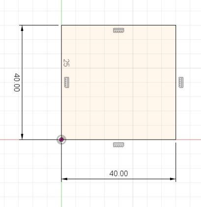
1. Sketching a 40mm by 40mm rectangle from Sketch > rectangle (Figure 7).
Figure 7. Sketching a rectangle.
2. Extruding the rectangle by selecting Create > Extrude, clicking the surface and then dragging it up and setting the height to 40mm.
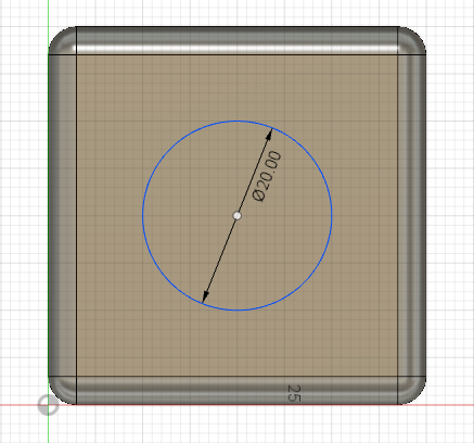
3. Adding 3mm fillet (round) to the edges of the cube from Modify > Fillet.
4. Sketching a 20mm diameter circle on each side of the cube from Sketch > Circle > Center diameter Circle (Figure 8).
Figure 8. Adding Fillet and skeching a circle.
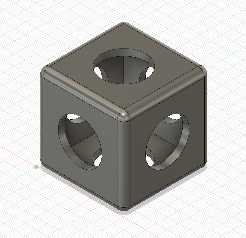
5. Removing materials from cube interior to create a hollow with a 3mm wall thickness. Modify > Shell.
6. Extruding cuts from each of the sketched circles to make the holes (Figure 9).
Figure 9. Making the holes.
7. Creating the ball, which should be inside the cube. This was done by using create > Sphere .
I set the sphere diameter to 25mm (the holes' diameter are 20mm) to be sure that it will get stuck inside the cube (Figure 10).
Figure 10. Making the ball.
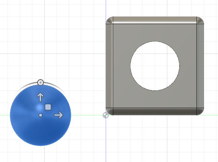
8. Moving the ball inside the cube using Create > move/copy. Just select the sphere and drag it along the axis you want (Figure 11).
Check the ball and cube from different views to make sure that there is no contact between them.
Figure 11. Moving the ball.
Figure 12. Final design.
3D Printing
I 3D-printed the ball and the cube that I designed using Fortus 380mc (Figure 13). As it mentioned above, it uses ABS (Acrylonitrile butadiene styrene) material in
Fused Deposition Modeling (FDM) technology. The printing process is controlled through the Insights software from a computer that is located next to the printer.
Figure 13. Fortus 380mc 3D printer at Fab Lab Oulu.
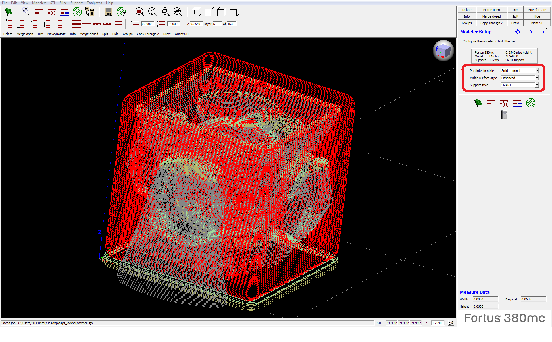
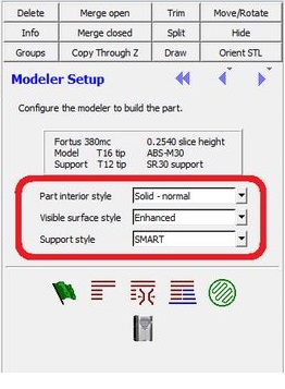
The printing process was quite straightforward. I imported my .stl file. Then, I mostly used the default settings to set up the printer.
Part interior style was 'Solid-normal', Surface style was 'Enhanced', and Support style was set to 'SMART' (figure 14). I pressed the green frag
and made each layer and supports visible. Then I pressed Tool Paths
and then Build.
I wore gloves to place a base sheet on top of the 3d printer's work base. Next I closed the door and waited for a while until the sheet get heated and flattened. Then I adjust the
placement of the printing part through the 3D printer's touch screen GUI. Finally I pressed Play on the Printer's GUI.
Figure 14. 3D printer settings.
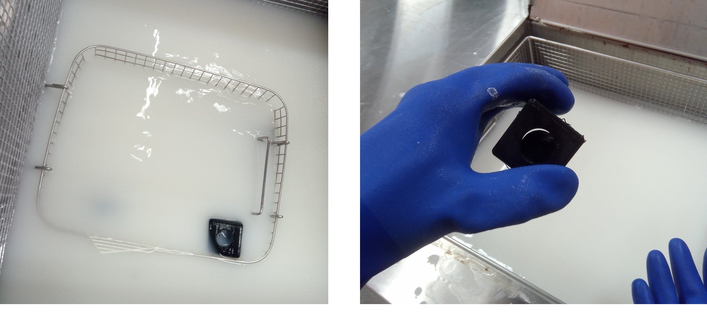
The printing process took a little more than a couple of hours. Since in my design, the ball was inside the cube, it could not have been built without using support material.
To remove the support material, I put the printed object into the cleaning tanks. So, I only needed to wait for the existing detergent in the tank to do the job. The 3D-printed design was left
into the tank over the night, so I do not know how long it took for all the support material to get solved. Remember to wear chemical-resistant gloves while you are working with
the cleaning tank.
Figure 15. Removing the support material.
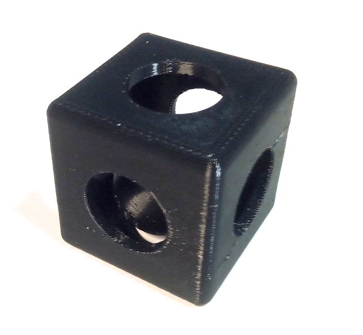
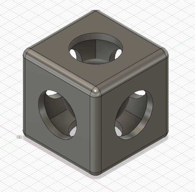
After removing the object from the cleaning tank, wash it and your hands carefully. Touching eyes with a detergent smeared hand
can cause burn and damage to your eyes. The final result can be seen in figure 11.
Figure 16. Final result.
3D Scanning
In order to make a 3D model of an existing object, I decided to utilize Autodesk ReCap Photo and 3DF Zephyr.
Both of them automatically reconstruct a 3D model from photos of the object, which are captured with various camera view angles. I found some useful tips here, that can improve
the result.
some of them were:
- Each photo of your photo set should have more than a 50% overlap at least with one other photo of the photoset.
- Be careful that there is no moving objects in the background.
- Do not use intense spotlight.
- Be careful that your own shadow does not fall over the subject (because you are changing your position,
the shadow over the subject will be different in different photos).
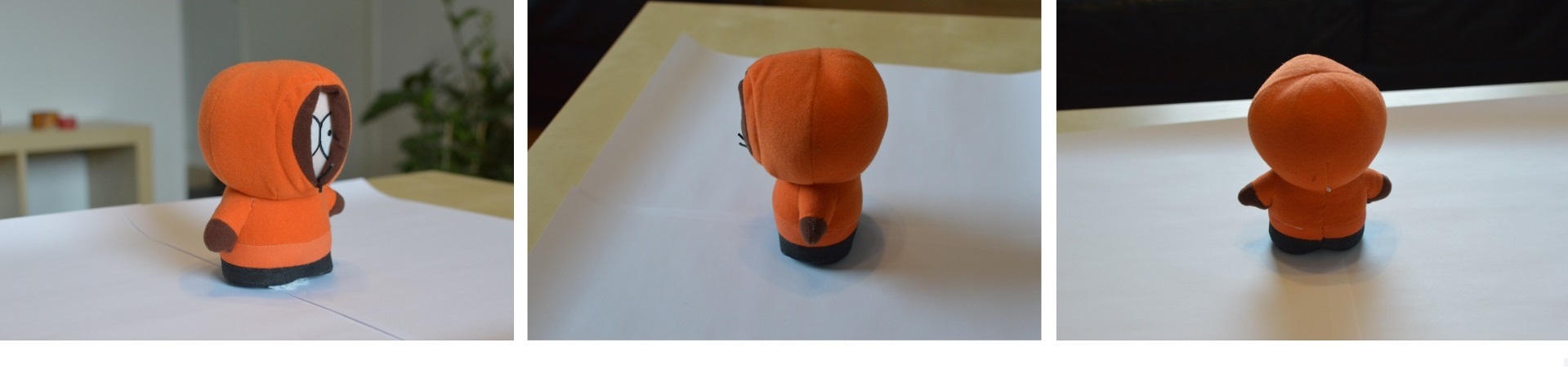
My setup was simple, I picked a fabric Kenny toy (almost 20cm high), and put it on the coffee table in my living room. I also put a couple of blank A3
papers under the toy in order to increase the contrast between the toy and the base surface (table). The lighting mainly was the daylight coming through the windows, which
were located in front of the subject.
I used a DSLR camera with a sharp lens (35mm f/1.8). The reason I used a sharp lens was that I wanted to have a nice bokeh (blur) on the
background of the image (to help the 3D reconstruction software to detect the main subject better). I captured 100 photos in total, figure 17 shows some of the photos.
Figure 17. Photo shoots samples.
The process of constructing the 3D model out of the photos, in both Autodesk ReCap Photo and 3DF Zephyer was quite straightforward. I followed these YouTube tutorials
(Autodesk ReCap Photo, 3DF Zephyer)
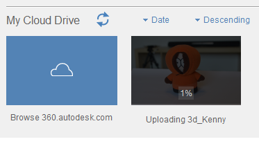
to do the job. There was just one issue with the Recap. After I imported the photos to the software, it started the process with uploading them to the cloud. Then, it started the process of constructing the 3D model.
The process was at 1% for more than an hour, and a 'waiting in queue' message was being shown (Figure 18). By searching the internet, I found out that it is normal and I just should wait.
Figure 18. Recap stuck at 1% waiting in queue.
The results for the 3DF Zephyer and Autodesk ReCap Photo are presented below.
Using 3DF Zephyer:
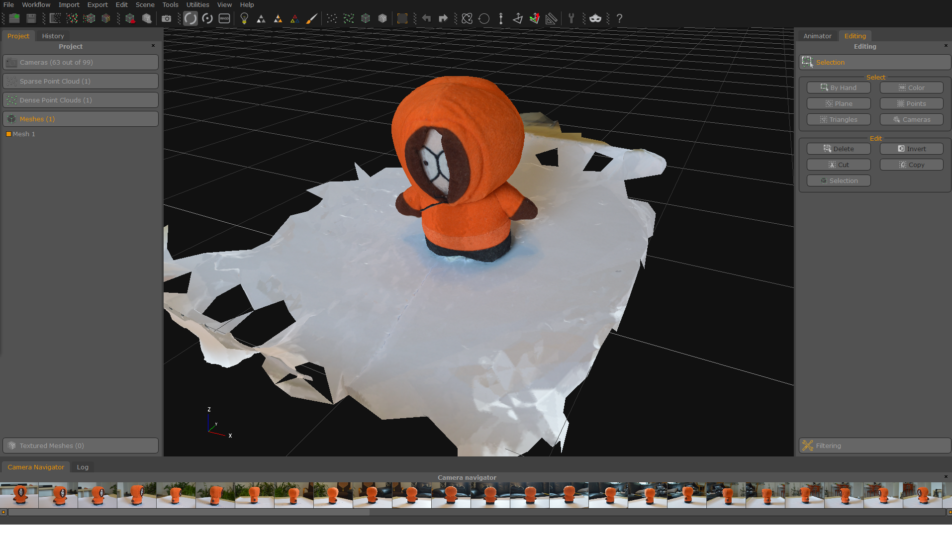
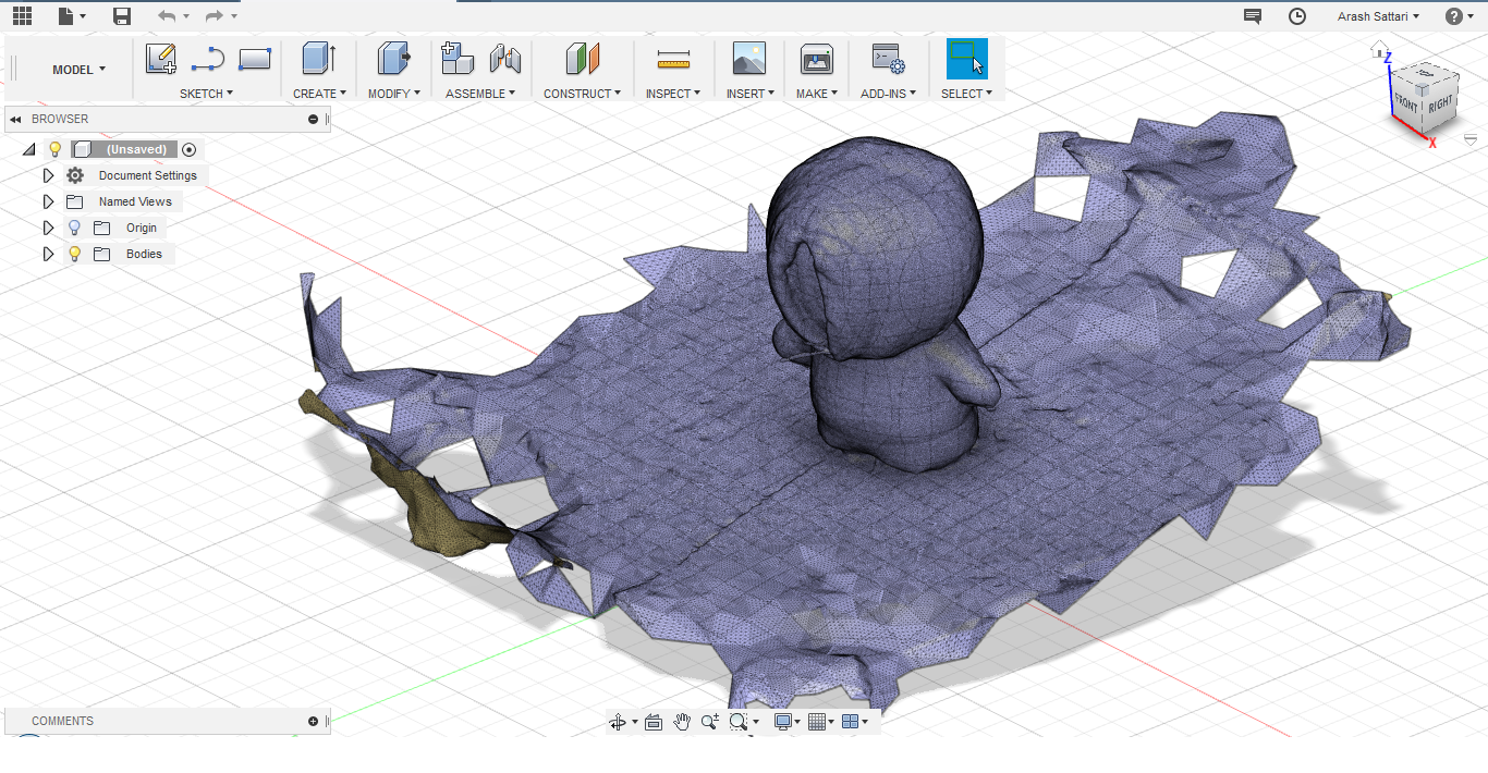
Figure 19 shows the 3d model in 3DF Zephyer and Figure 20 shows the imported mesh into Fusion 360.
Figure 19. 3D model constructed by 3DF Zephyer.
Figure 20. The mesh imported init Fusion 360.
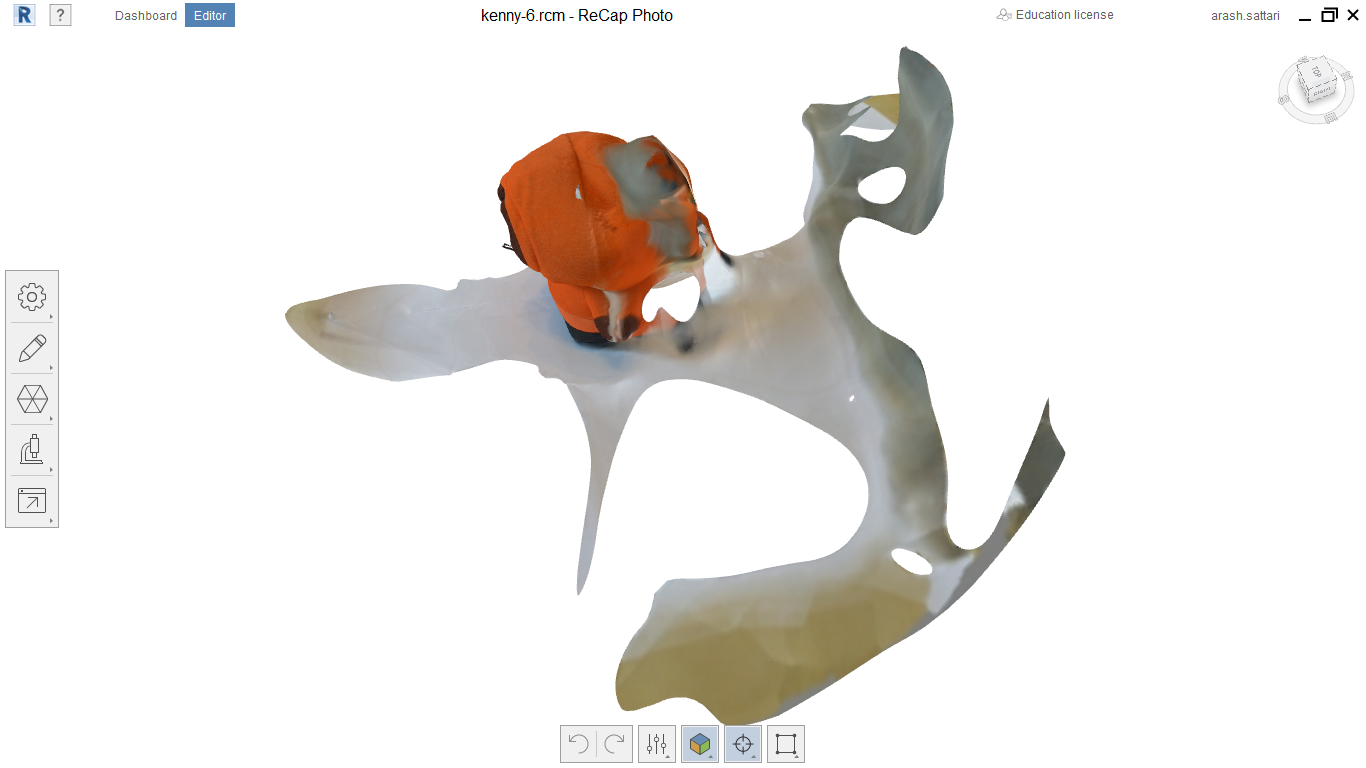
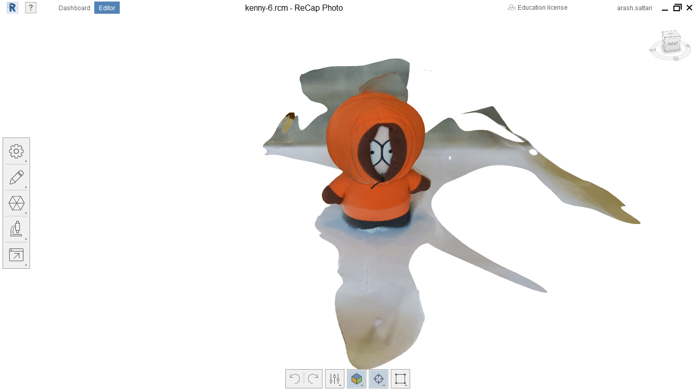
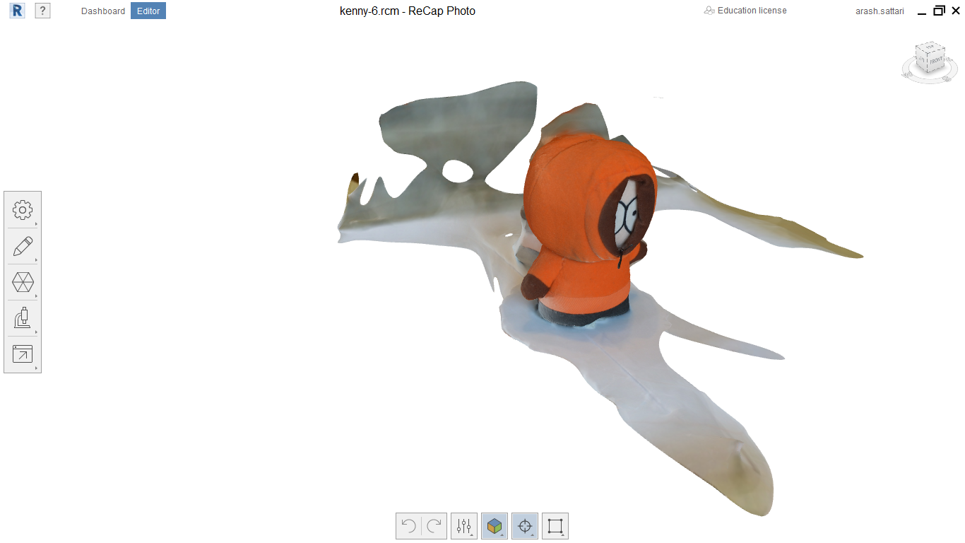
Using Autodesk ReCap Photo
I used exactly the same set of photos to create a 3D model in Autodesk ReCap Photo. As you can see in figures 16 to 18, the result is not comparable to 3DF Zephyr.
Figure 21. 3D model constructed by Autodesk ReCap Photo
Figure 22. 3D model constructed by Autodesk ReCap Photo
Figure 23. 3D model constructed by Autodesk ReCap Photo
Reflection
This was my first time I had 3D printed an object. So I learned about different 3D printing technologies, and how to work with different
3D printers that are in our FabLab. It was also my first 3D scanning and was quite impressing.
 and made each layer and supports visible. Then I pressed Tool Paths
  and then Build
  .
.