Week Assignments
Group Assignment:
● Characterize your lasercutter. Make test part(s) with varying cutting settings and dimensions.
Individual Assignments:
● Cut a sample using the vinylcutter.
● Design, lasercut, and document a parametric press-fit construction kit, accounting for the lasercutter kerf,
which can be assembled in multiple ways.
Group Work
Measuring the kerf:
Kerf is the width/thickness of a cut made by the cutting tool as it cuts through different material such as wood, cardboard,
acrylic, etc. (i.e. the width of material that is removed by a cutting process) 1.
It is important to know the kerf so that the pointer of the cutting process (laser, water jet, etc.) can be slightly offset to allow it.
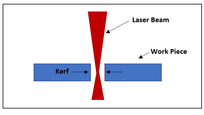 Figure 1.
 Laser Cutting Kerf.
Alok,
Michael and I worked as a group for this assignment.
Before starting, safety issues were explained to us by Behnaz. The main ones are summarized here:
● Never leave a working laser cutter unattended.
● Always keep an inspected fire extinguisher around the laser cutter.
● Make sure that AIR VENTILATION is ON.
For this and the press-fit construction task, we used an Epilog Laser cutter and defined different settings for cutting.
Figure 2 shows the laser cutter, its control panel where the origin and position the cutter is set, and the different
settings on the computer for defining the cutting parameters when sending a file. The settings differ depending on whether
one is:
● engraving (raster - created with pixel-based programs),
● cutting (vector - created with vector-based software that is focused on drawing shapes and their outline), or
● both (combined) (described below).
In the dialog box (figure 2-3) for printing under advanced settings, you can also choose the material for printing. These include cardboard,
MDF, acrylic of different thicknesses, which are defined in the program.
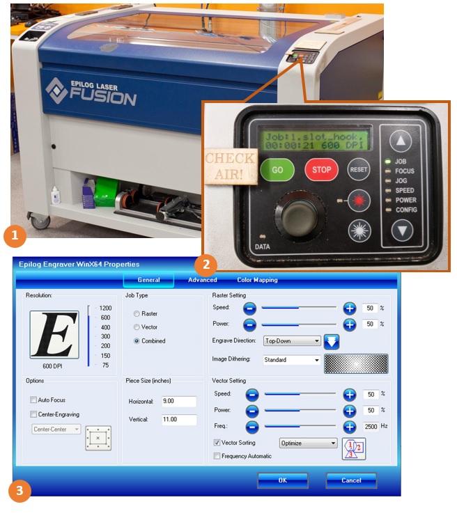 Figure 2.
 Laser cutter and its setting menus.
In the laser cutter’s control panel (figure 2-2):
JOG: To set the origin (upper left corner of the PDF file is considered as the origin). First, select the JOG from the laser cutter’s control panel using
the up and down arrows. Next, press the red button on the panel to see the current laser head position by a visible red light. Then, position the laser with joystick.
Finally, when the laser is positioned, press the joystick to set the JOG.
FOCUS: To focus the laser beam on the material. First, select the JOG from the laser cutter’s control panel using the up and down arrows. Next, position the calibrator.
Then, use the joystick and move the laser cutter table up or down, so that the calibrator just touches the surface of the material (figure 3).
JOB: To select the work to be cut or engraved from the printing queue. There might be multiple jobs sent to the laser cutter and it is important
to do this before cutting to ensure that the right one is selected. Use the joystick to select the right job. An estimated cutting time will be displayed on the control panel.
After all the settings are done, press GO and the cutting will start.
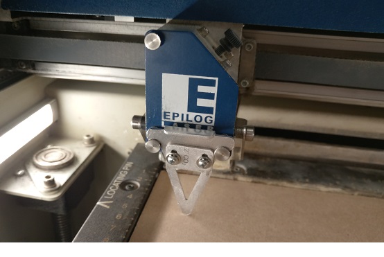 Figure 3.
 Focus Calibrator.
To make the test parts, we designed a measuring tool in Inkscape with eight slots of varying sizes that were equally positioned across a rectangular diagram.
The width of each slot was 10 mm minus the number indicated on the base of the slot.
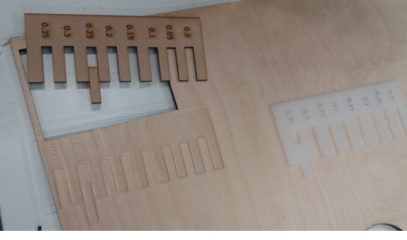 Figure 4.
 A kerf measuring tool designed in Inkscape.
We had another rectangular piece 10 mm wide and this was used to measure the kerf. We tested this piece with the different slots to see into which it fits.
We considered half of the number on the base of the slot as the kerf for the laser cutter machine for the type of material we used. Figure 5 outlined the
design method. The left image in figure 5 is the slots and the dotted lines indicate the laser beam path. The right diagram in the Figure 5 is the test piece.
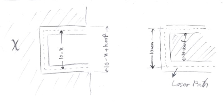 Figure 5.
 Our designed kerf measuring tool method.
When the test piece fits into a particular slot, it means that the width of the test piece is equal to the width of the slot. The basic equation
used to calculate the kerf is shown below:
10 - x - kerf = 10 - kerf
kerf = x/2
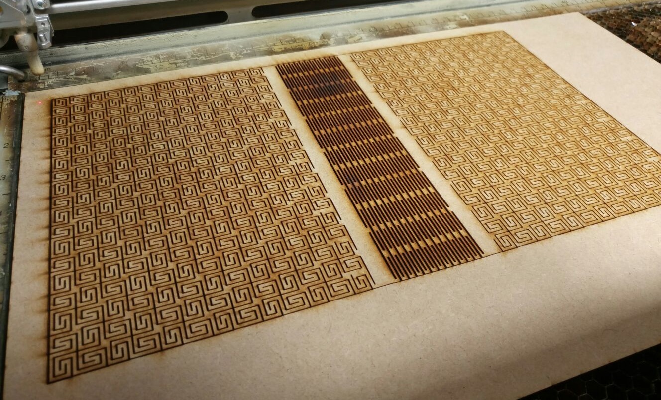
We also changed the settings of the lasercutter to see the effect on the material being cut. For cutting, we changed the power (the power of the laser beam).
We first tried 20% and then the 40% shown in figure 6-1.
We also did the same for engraving, where we changed the settings for speed (how fast the laser moves throughout the material) and power. For engraving,
we noticed that when the speed is low and the power is high, there were burning traces produced around the engraved area. The best outcome was when the speed
was high and the power was reduced as seen in the rectangle on the right with settings of 60% for speed, 30% for power and 50% for frequency in Figure 6-2.
Frequency is always constant or at least we could not change it when we were trying different laser cutter settings.
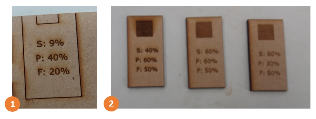 Figure 6.
 Cutting and engraving using different settings.
Etched Glass
I decided to make an etched glass by sandblasting technique. To accomplish the job, first I made a vectorized image using Inkscape,
then I used the vinylcutter machine to cut the image on a vinyl film and finally I placed the film on the glass and sandblasted the glass.
The steps are illustrated below:
Inkscape
1. Choosing a JPG image from internet as the artwork.
2. Removing the image's background using Magic Wand tool in Paint.NET. Then, increasing the contrast.
(Paint.NET is a freeware raster graphics editor program for Microsoft Windows)
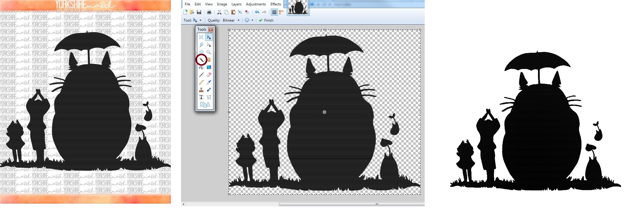 Figure 7.
Removing the background from the image.
3. Vectorizing the image.
4. Selecting Edit path by nodes from the left panel (or press F2), then clicking on the vectorized image.
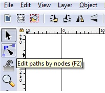 Figure 8. Selecting Edit path by nodes.
5. Removing the filling paint by selecting No paint from Fill tab in the Fill and Stroke panel.
6. Exposing the borders by selecting Flat color from Stroke paint tab in the Fill and Stroke panel.
7. Setting the stroke width to 0.5mm.
8. saving as a SVG file.
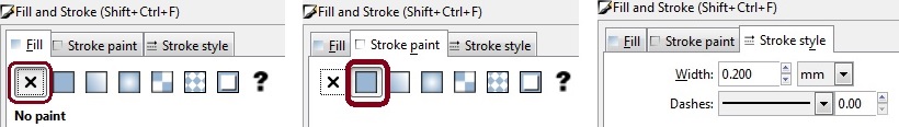 Figure 9.
 Vinyl Cutting
Our Fab Lab has a Roland GS24 Vinyl cutter. These steps should be done to cut on the vinyl film using the machine:
1. Push down the loading lever, which is located at the top left of the vinyl cutter.
2. Place a piece of vinyl film and align the pinch rollers on the determined grit marks.
3. Pull the loading lever up.
4. Select the type of vinyl film that is being used (piece, roll or edge). I used a piece of film, therefore, I selected piece.
5. Press the Enter button, which is located at the right side of the machine. The machine starts to measure the size of vinyl film.
6. Set the origin using the arrow buttons that are located at the right side of the machine.
7. Open the SVG file in Inkscape and select print.
8. Open Printing preferences and select Cutting area > Get from machine.
9. Change the height to the design (SVG file) height.
10. Press Accept. and send the file to print.
When the vinyl cutter has finished the job, the unwanted area should be peeled off from vinyl sheet to obtain the exact design. I started from one corner of the sheet and peeled away the film by hand (figure 10).
Then I removed the smaller part with a tweezers.
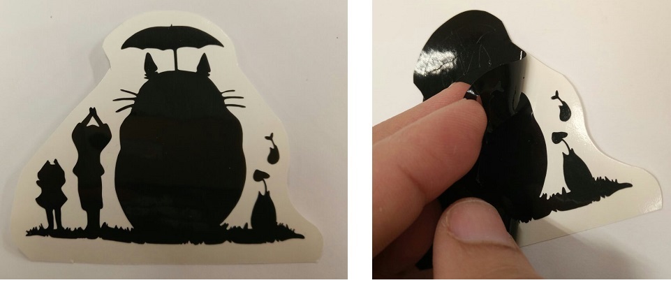 Figure 10.
 Peeling off the extra area.
Sandblasting
I used transfer paper to place the design from the vinyl sheet to the glass. First I laid a piece of transfer paper down on top of the design and press it well. Next I peeled off the back paper from the vinyl sheet.
Then, I sticked the design on the glass, and finally I sandblasted the glass using the sandblaster machine in the FabLab (figure 11). The final result can be seen in figure 12.
 Figure 11. sandblaster
 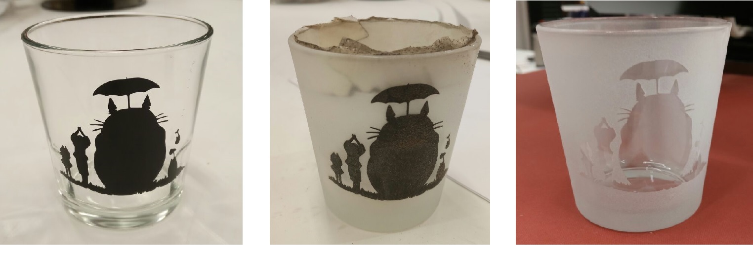 Figure 12. sandblasting process
Snap-lock Joint
I made a snap-lock irreversible joint as the press-fit construction kit. The design was done in Fusion 360. The process that I followed to create the pieces were:
Designing the blade with hook slot:
1. Defining the parameters at MODIFY > Change Parameters
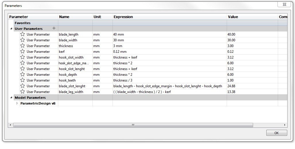 Figure 13. Defining the parameters.
2. Sketching a rectangle as the base of slot piece (blade_width by blade_length).
3. Extruding the rectangle and giving it the thickness.
4. Sketching a rectangle (thickness - kerf long) and using extrude (-blade_slot_length) to make the main slot in the blade.
 Figure 14.
5. sketching a square (hook_slot_length) and using extrude to make the hook slot.
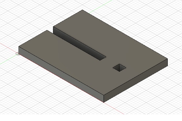 Figure 15.
 Designing the blade with hook:
1. Sketching a rectangle as the base of slot piece and assigning thickness to it (blade_width by blade_length).
2. Sketching two rectangles, then extrude cut them. The smaller one is thickness - kerf wide an extruded cut -hook_slot_edge_margin deep. The bigger
rectangle is hook_depth + hook_slot_width by thickness × 3.
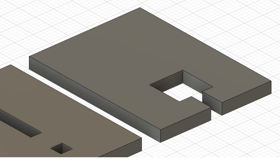 Figure 16.
4. sketching a rectangle (hook_depth+thickness-0.5mm by thickness) and extruding it (select new body).
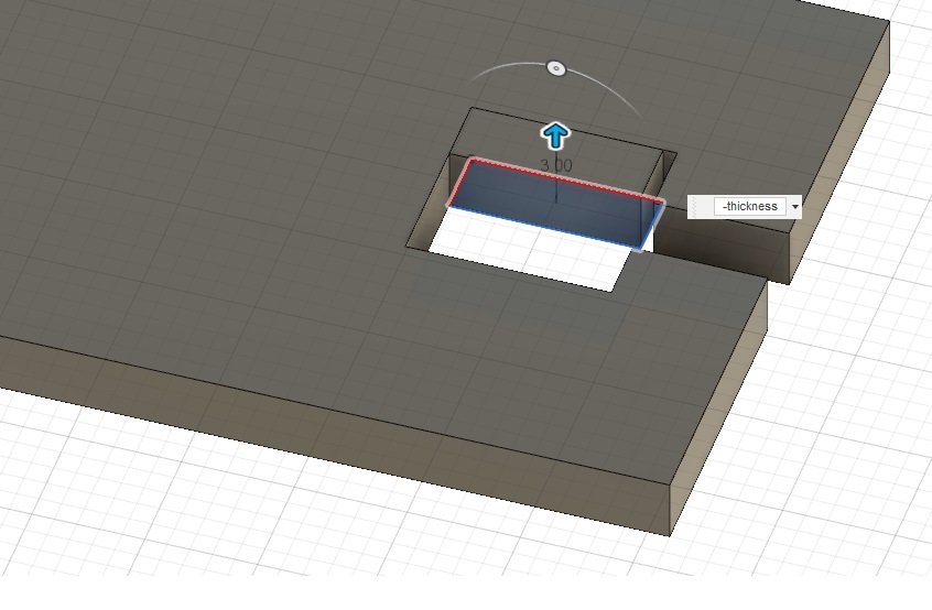 Figure 17.
5. To apply the bevel in the hook use MODIFY > Chamfer
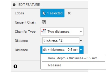 Figure 18.
6. To make the hook teeth sketch a right rectangle (
hook_teeth by
thickness-0.5mm), then extrude it to give it the thickness and finally apply bevel to its edge.
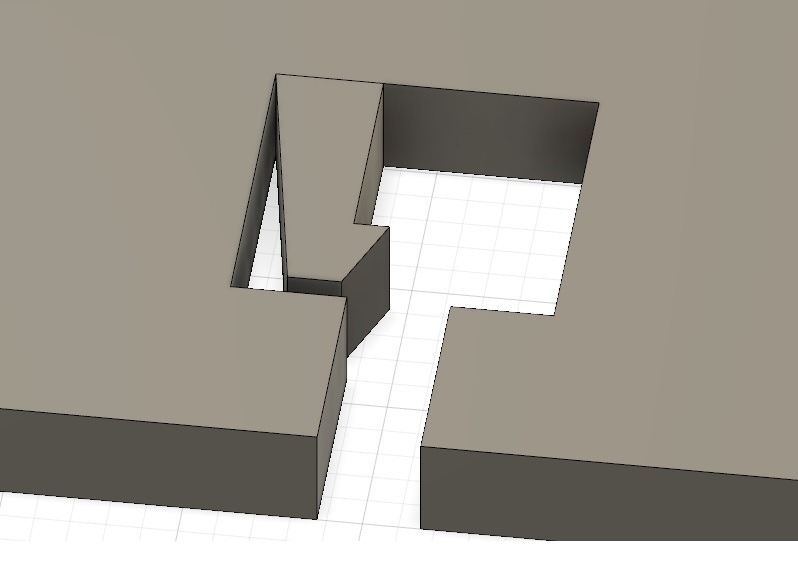 Figure 19.
7. Select the side of hook that is designed, then mirror it from CREATE > Mirror.
8. Select the second side of hook from body panel, then right click on the body and select MOVE / COPY.
and set the Move Type to Point to Point. Finally, click on the edge point of the hook body and then, click on the destination point.
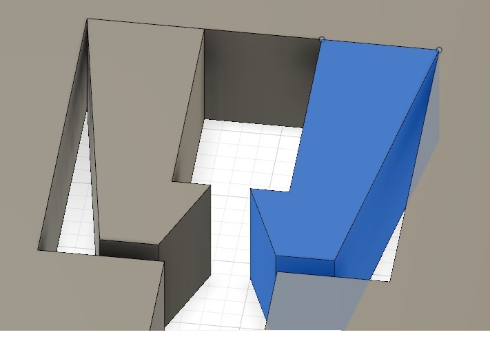 Figure 20.
9. Selecting hook parts and the main part, then choosing Modify->Combine to join the parts.
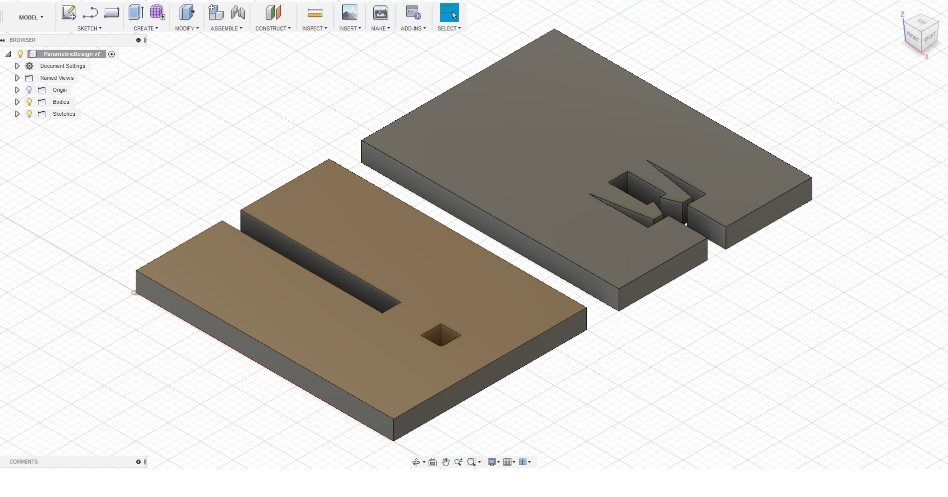 Figure 21.
 Creating a SVG file for laser cutting:
1. select the sketch that we want to cut
2. right click on it and select Save As DXF
3. open the DXF file in Inkscape with original size
4. Select these properties for the lines:
5. fill: no paint
- Stroke paint: flat color
- Stroke style: 0.02mm
- save the file as SVG
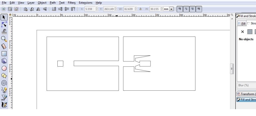 Figure 22.
 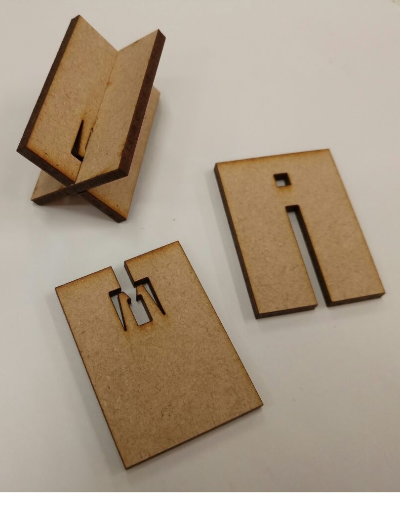 Figure 23.
Reflection
During this week, I worked with the vinyl cutter and sand blaster to etch on a glass. In addition, I designed parametric 3D models in Fusion 360. But, defining the
parameters properly is still a challenge for me. I think I need more practice to get used to parametric designing. I also learned what is the kerf
and how should I consider it in my designs.