8. Computer-controlled machining
In this week, I learned how to prepare a 3d-designed file for milling and how to use the CNC Router.
Assignment
Group assignment
- For the group task, we are to test runout, alignment, speeds, feeds, and tool paths for the milling machine.
Individual assignment
- The individual assignment was to make something (big).
Group assignment
For this week’s group assignment, we all did it as a group. Eino Antikainen, our instructor for the week, took as through the process of creating a file, setting the tools paths and exporting it for milling. Then Eino showed as how to use the CNC Router.
Operating the CNC Router
The process for creating the nc file for milling is outlined in the following section under CAM settings. Next, I describe the operation of the machine.
The process involves selecting (if they are not in place) the right milling bit, the CNC tool collet (in our case of 8mm diameter) and putting it in the collet clumping nut, tightening them on the Router and inserting the milling bit.
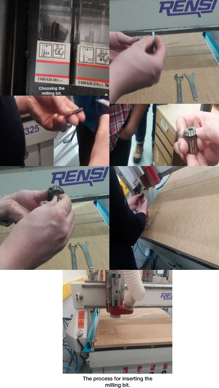
Then, powering on the machine and starting NcStudio (the software for operating the CNC Router) from the computer and setting the X, Y, and Z axes (the starting point for the milling process). The process for setting the axes can be done from the computer or with a handheld controller. For the Z axis (vertical position), there is also an option to automatically calibrate the vertical starting position of the bit.
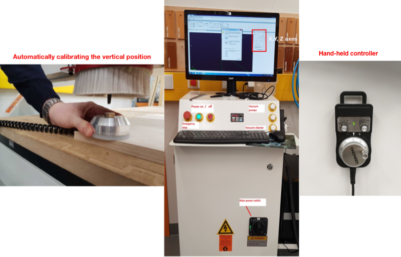
The X, Y and Z axes should be 0 when correctly positioned (W. Coor in the image below). Although for the Z axis, if the automatic calibrator is used, Z should be 45. Then, you upload the nc file, simulate it, reduce the Feedrate and Spindle values which can affect the quality of the milling process. The Feedrate should be set at about 80% of the maximum 6000 mm/min and Spindle speed also at around 80% of the maximum 15000 rpm. Finally, press the play button. We opened the design file that supports CMC machine (NC file). Once all the settings are ready, the board to be milled can be secured on the surface of the Router to ensure that it is cut as evenly as possible.
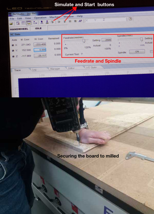
Feedrate and spindle and securing the board
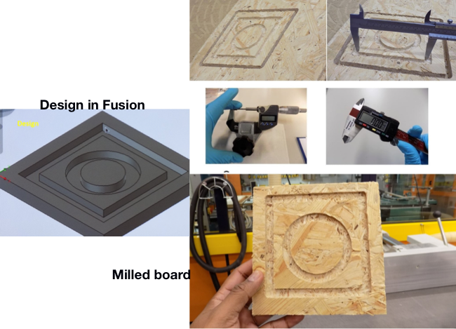
Below are images of Eino’s designed test file and the cut board for the group work.
 .
.
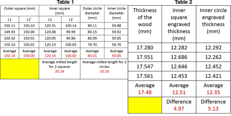
The measurements are also presented below. The average milling length for 2 squares is 20.14 mm while the average milling length for the 2 circles is 20.16 mm. Both the values are close, and error is minimal in comparison with the 3D design file (Table 1). We also measured the engraved area from the square and circular engraved thickness before and after milling using digital screw gauge. The results and difference in thickness of the squared and the circular areas are presented in table 2 below.
 .
.
Individual assignment
Designing a Laptop Stand
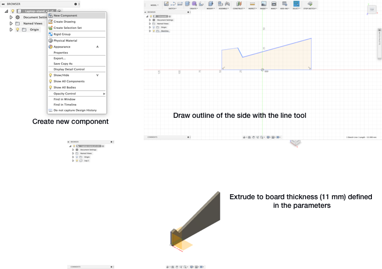
I thought to make something related to my final project but could not settle on the design, so decided to make a laptop stand instead. The material available for milling was Oriented Standard Board of 11 millimetre thickness which the design had to correspond to. Before beginning the design, I set different parameters for the laptop as outlined in Week04. Then under BROWSER in Fusion, I named my design and created a new component and named it leg. Using the line tool, I drew an outline of the side of the laptop stand, applied some constraints and then extruded (CREATE>Extrude) it.
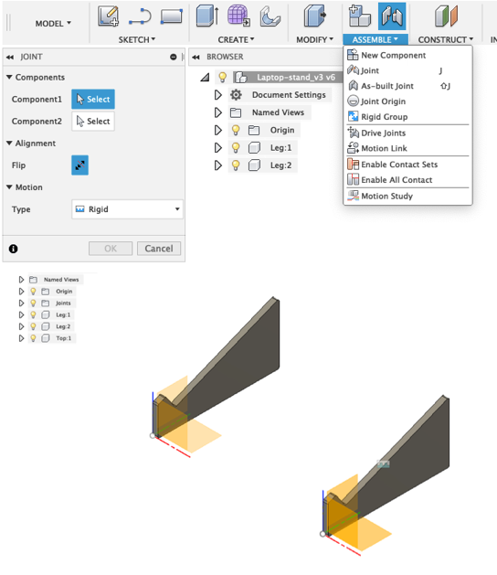
I then copied and pasted the leg component and positioned it 340 mm from the original one using the offset tool found in ASSEMBLE>Joint. Copying and pasting the component ensures that changes made in one are automatically applied in the other. This is the width of the top component of the laptop that was also defined in the parameters.
I created a new component for the top part, created a new sketch and with the Rectangle tool, drew a 2-point rectangle. Using constraints, I positioned it on top of the two legs. I drew a tab on the top edge of the base where it touches the leg, applied constraints to position it and mirrored (CREATE>Mirror), across the base to get four tabs.
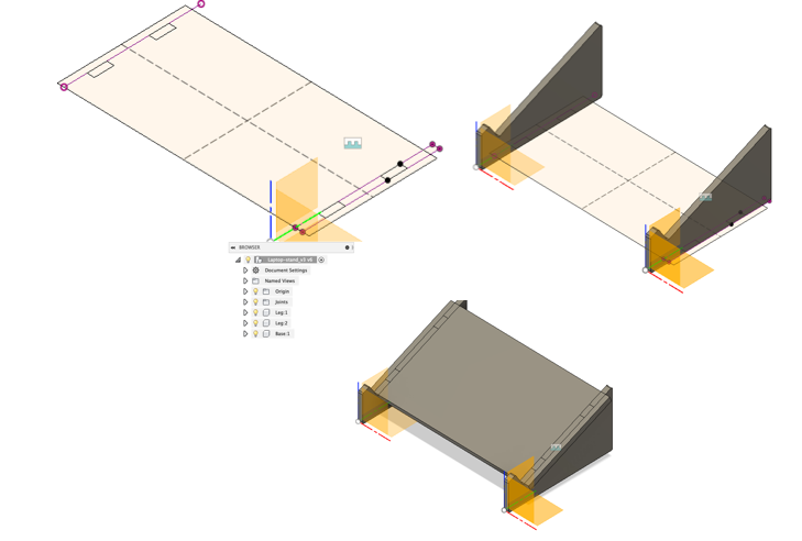
Then I selected all the profiles I needed and extruded down by -11 mm (the board thickness). After this, I performed a boolean operation (MODIFY>Combine) to subtract parts from the combined components and create slots.
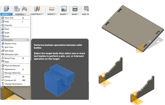
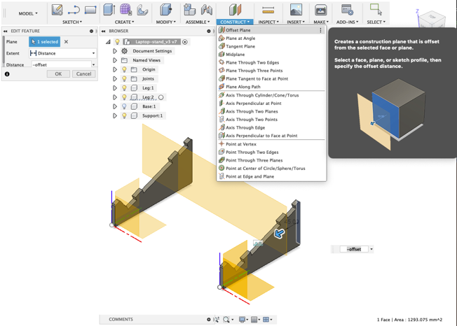
I modelled new supports by creating a new component and naming it support. The support was to hold the legs in place. On a new sketch, I modelled the supports by first creating an offset plane (CONSTRUCT>offset Plane).
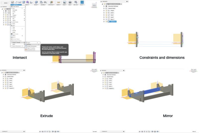
In order to see the intersection of the legs on the new offset plane you select SKETCH>Project/Include/Intersect. Then draw a rectangle, apply constraints and dimensions to position the support, create tabs as above but divide the thickness by half. Extrude it on a new plane (Construct>Midplane) and mirror (CREATE>Mirror) the support by positioning it further inside.
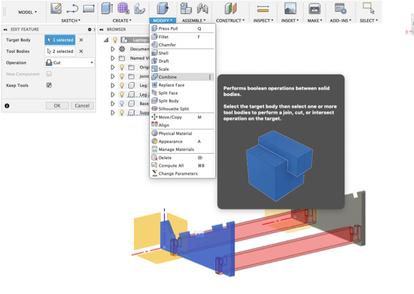
Then, I combined (MODIFY>Combine) the supports with the legs and rounded (MODIFY>Fillets) the edges.
This is the final result.
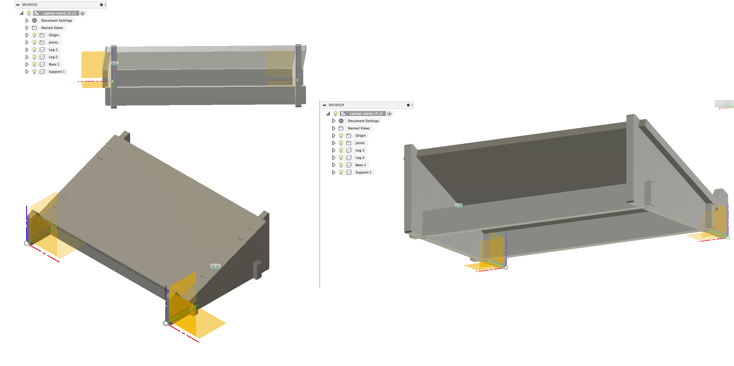 .
.
CAM settings
For creating the tool paths for milling, our instructor Eino Antikainen instructed us to download the CAM processor file and the setting files with values for different milling bits (included below in original files) from the Fab Lab Oulu Wiki site and add them to Fusion. Then, Eino also helped with the CAM settings, which were initially very confusing.
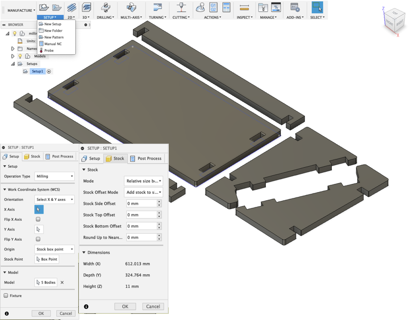
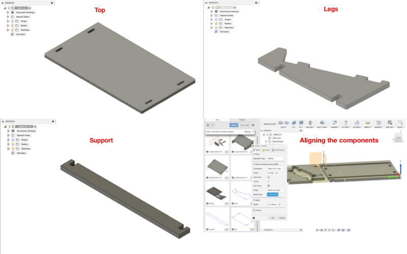
I arranged the components on a straight plane in preparation for creating the tool paths and then set the initial general properties for machining operations.
In Fusion’s manufacture workspace, we first went to SETUP>New Setup where we defined the Operation type, Orientation, Origin, and Box point in Setup options. Under Stock options we change all the offset values to 0mm and we can see the dimensions of the components as shown in the image below. It is important to ensure that the Height (Z/vertical axis) is the width of the actual board that will be milled.
 .
.
2D Pocket settings
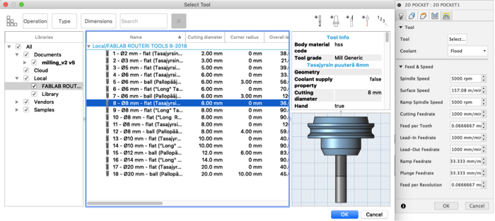
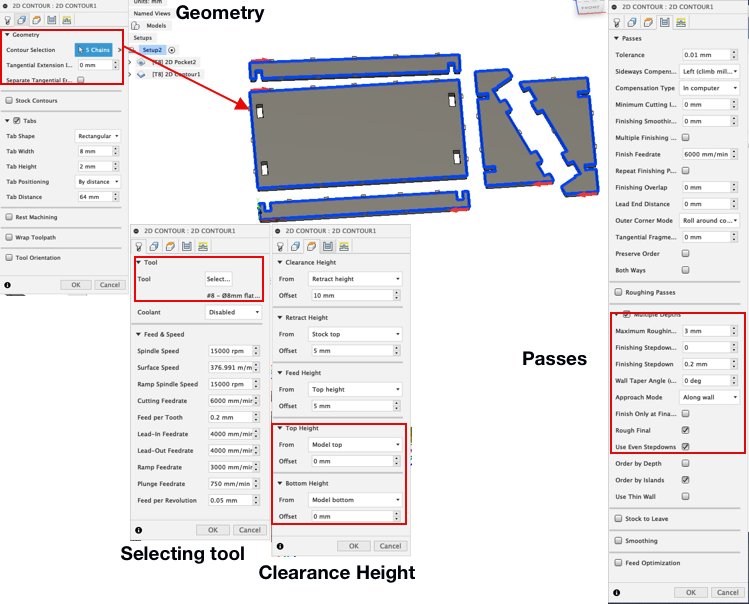
Under 2D>2D Pockets dialogue box in the Tool tab, you choose the milling bit from (the one we dowloaded from Fab Lab Wiki site). The milling bit is the 8 mm flat that is highlighted in the image below.
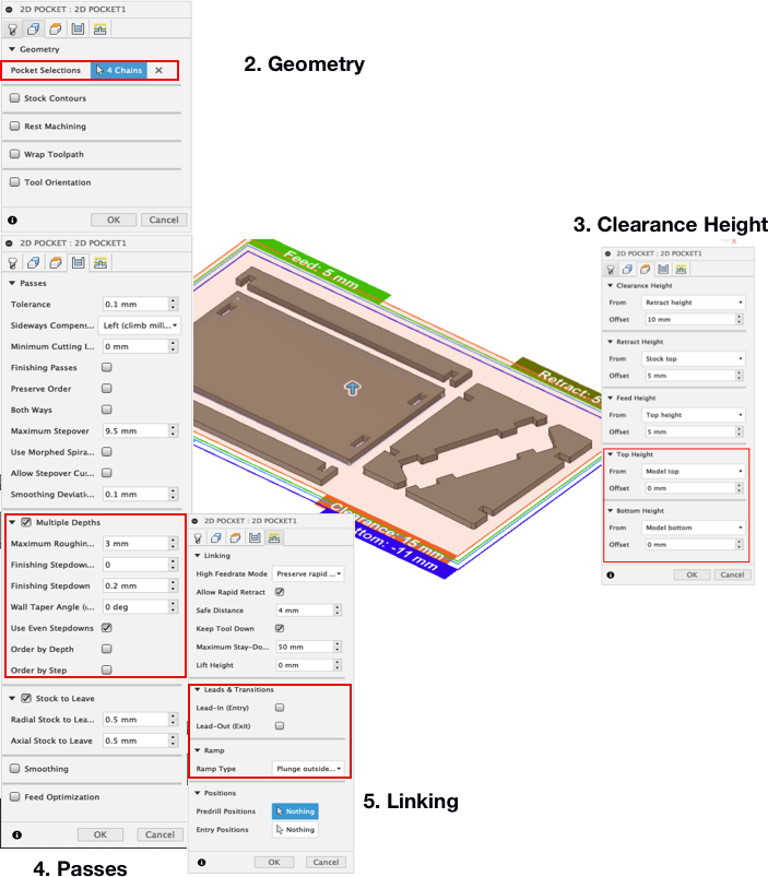
In the Geometry tab, you select the areas where you want to make tabs/pockets. In the Clearance Height tab, you set the top and bottom heights. In Passes tab, you set the maximum depth for drilling using even step downs. In Linking tab you deselect Leads and Transitions and set the Ramp Type—how the cutter moves down for each depth cut—to Plunge.
2D Contour settings
I then selected 2D>2D Contours and the below image shows the changes made which were mostly similar to those in the 2D pockets.
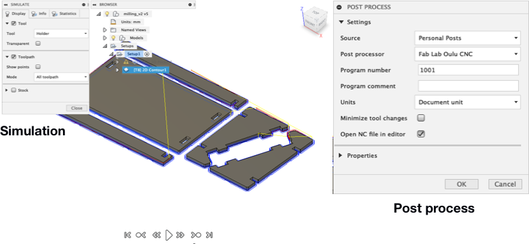
I then simulated the tool paths and stock material removal and created the post processor file recognised by the CNC Router.
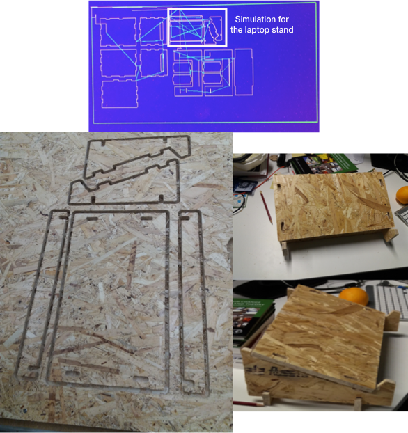
After creating the tools and exporting the nc files, I went through the same process outlined in the group work for operating the CNC Router.As mentioned above in the group work, I set both the Spindle speed (r/min) and Feedrate (mm/min) to be around 80% of their totals. These can be adjusted during cutting based on the performance of the machine and/or the material to be cut. If the values for Feedrate and Spindle are too high, there might be vibrations and a creaky sound when milling. Operating the machine with too much force and speed should be avoided. As my design was small, I used the same board as Sahan and Jobin for milling. Below are images of the final result.
Reflection
I found this week’s assignment interesting. It is a process (from CAD to that I never really think about and it was interesting to learn about converting 3D designs to nc files that can be manufactured.
Aligning the components of the laptop stand in preparation for milling was a challenge as there were components that mirrored each (were not separate) so they could not be arranged on flat surface. I had to first save each of the parts (top, legs, and support) as DXF files, import them to Fusion, Extrude them to the thickness of the board and align them.
After milling is done, the process of cutting out the milled board from the surface of the Router was not a pleasant one, even though I did not make something big. I also defined the wrong measurements in the parameters and the stand’s top part was wider than the laptop. This was just a trial and I am not planning to use the stand. Summarily, it was fun learning how to use the Router
Original Files
- Fusion - Laptop stand - Fusion file / Top - DXF file / Legs - DXF file / Support - DXF file
- NC file - Laptop stand