16. Interface and application programming
In this week, I wrote a simple application that interfaces a user with an RGB LED.
Individual assignment
Write an application that interfaces a user with an input &/or output device that you made.
Group assignment
Compare as many tool options as possible.
Group Assignment
We all did the group assignment together. Few of us used Processing, one used Blynk, one PyQt5 and others planned to use MatLab or Python.
A comparison of some of the different programs below and details of Processing, which I used, are in the individual assignment section.
Blynk
Blynk supports hardware platforms such as Arduino, Raspberry Pi, and similar microcontroller boards to build hardware for your projects.
Blynk supports the following connection types to connect your microcontroller board (hardware) with the Blynk Cloud and Blynk’s personal server:
- Ethernet
- Wi-Fi
- Bluetooth
- Cellular
- Serial
The Blynk platform includes the following components:
Blynk app builder: Allows to you build apps for your projects using various widgets. It is available for Android and iOS platforms.
Blynk server: Responsible for all the communications between your mobile device that’s running the Blynk app and the hardware. You can use the Blynk Cloud or run your private Blynk server locally. Its open source, could easily handle thousands of devices, and can even be launched on a Raspberry Pi.
Blynk libraries: Enables communication with the server and processes all the incoming and outgoing commands from your Blynk app and the hardware. They are available for all the popular hardware platforms.
Hello world with Blynk looks like this:
BLYNK_LOG1("Hello World"); // Print a string
PyQt5
Qt is set of cross-platform C++ libraries that implement high-level APIs for accessing many aspects of modern desktop and mobile systems. These include location and positioning services, multimedia, NFC and Bluetooth connectivity, a Chromium based web browser, as well as traditional UI development.
PyQt5 is a comprehensive set of Python bindings for Qt v5. It is implemented as more than 35 extension modules and enables Python to be used as an alternative application development language to C++ on all supported platforms including iOS and Android.
PyQt5 may also be embedded in C++ based applications to allow users of those applications to configure or enhance the functionality of those applications.
Hello world widget with PyQt5:
import sys
from PyQt5.QtWidgets import QApplication, QWidget
if __name__ == '__main__':
app = QApplication(sys.argv)
w = QWidget()
w.resize(250, 150) w.move(300, 300)
w.setWindowTitle('Hello World')
w.show()
sys.exit(app.exec_())
Python
Python is an interpreted, high-level, general-purpose programming language used for developing both desktop and web applications. Python is also used for developing complex scientific and numeric applications and its design philosophy emphasises code readability with its notable use of significant whitespace.
A simple program for addition and calculating savings in Python is presented below :
# Create a variable savings
savings = 100

# Create a variable factor
factor = 1.10

# Calculate result after 7 years
result = savings * (factor ** 7)

# Print out result
print (result)
Hello world is simply printing it print(“Hello, World!”), or you can save it in a variable as above and print it.
For the assignment, we followed this example for controlling an RGB LED with Python and Arduino. The files are linked at the end.

A video of the Python interface below.

Files
- Python - RGB Control
- Arduino - RGB Control 2
Individual assignment
When earlier thinking about the assignment for this week, I had planned to try out writing an application in Python and at least one other tool. After reviewing Processing, I settled on this.
Introduction to Processing
Processing is a flexible software sketchbook and a language for learning how to code within the context of the visual arts and is primarily used for learning and prototyping.
- Free to download and open source.
- Interactive programs with 2D, 3D, PDF, or SVG output.
- OpenGL integration for accelerated 2D and 3D.
- For GNU/Linux, Mac OS X, Windows, Android, and ARM.
- Over 100 libraries extend the core software.
- Well documented, with many books available 1.
I couldn’t attend the local lecture, so missed the introduction given by Ivan. To get familiar with Processing, I went through the Overview and few Tutorials from Processing’s website. I also went through the examples (File > Examples…) available from Processing’s IDE which cover different topics such as Arrays, Objects, Shapes etc.
In Processing, you can write both static sketch (programs written as a series of statements) and an interactive sketch (programs written as a series of frames). In static sketches, a series of functions are used to perform tasks or create images without any interaction or animation. For example,
 size(400, 400); // Defines the dimension of the display window width and height in units of pixels
 background(192, 64, 0); Sets the colour used for the background of the Processing window.
 stroke(255, 128, 0, 128); // Sets the colour used to draw lines and borders around shapes.
 line(150, 25, 270, 350); // Draws a line (a direct path between two points) to the screen.
Whereas interactive sketches are created by adding built-in functions that are called automatically as shown below.
 void setup() { // runs once and used for any initialisation
   size(400, 400); // should always be the first line inside setup()
   ellipse(width/2, height/2, 50, 50); // Always the middle, no matter how the size() line changes
   stroke(255);
   background(192, 64, 0); // used only once when inside setup
 }

 void draw() { // used to handle animation
   //background(192, 64, 0); // when moved here, a single line that follows the mouse is drawn clearing the displying window.
   line(150, 25, mouseX, mouseY); // starting position of the line and detecting the movement of the mouse
 }

 void mousePressed() { // called whenever the mouse is pressed
 }
Connecting Arduino to Processing
Blinking an LED
After going through the above examples, I searched for examples on how to connect Arduino to Processing and send data over the serial port. This one from SparkFun outlined both talking and listening to the flow of data in both directions involving an agreement of when to send and receive (“handshake”). It was a good and easy to follow example of communication over serial. Serial is used for communication between the Arduino board and a computer or some other device. The process for serial communication, at least in Arduino, was also outlined in the Networking and Communication week where we connected and sent data to different network nodes. For this set up, I used an Arduino Uno which I connected to my computer using a USB cable.
For serial communication between Arduino and a computer, the SoftwareSerial Library should be included, then you define the serial pins (RX and TX), and initialise the serial communication and set the baud rate.
#include <SoftwareSerial.h>

#define RX    0
#define TX    1

SoftwareSerial mySerial(RX, TX);

char val; // Data received from the serial port
int ledPin = 8; // No. of the LED pin
boolean ledState = LOW; //to toggle our LED


void setup() {
  pinMode(ledPin, OUTPUT); // Set pin as OUTPUT
  mySerial.begin(9600); //initialise serial communications at 9600 bps
}
The Serial library reads and writes data to and from external devices one byte at a time … This library has the flexibility to communicate with custom microcontroller devices and to use them as the input or output to Processing programs 2.
In Processing, you also import the Serial library, declare the Serial object, initialise the serial port and set the baud rate. The process is briefly presented below:
import processing.serial.*; //import the Serial library

Serial myPort; // the Serial port object
String val;   // Data received from the serial port

void setup() {
  size(200, 200);
  printArray(Serial.list()); // List all the available serial ports:
  myPort = new Serial(this, Serial.list()[1], 9600);  // initialise serial port and set the baud rate
}
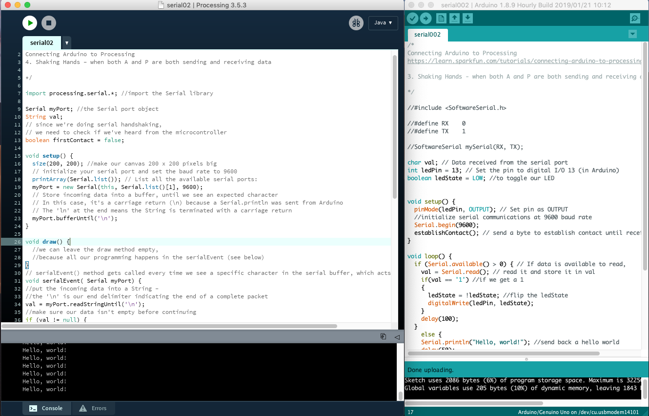 Connecting Arduino to processing
Processing receive’s “Hello World!” from Arduino and sends a “1” back to Arduino to toggle the LED. Arduino, has to be able to send “Hello World!”, while listening for a “1” from Processing. When you run the sketch, “Hello world!” is printed in the console and clicking in the Processing window (if (mousePressed == true)), turns on the LED that is connected to Pin 13 in the Arduino. The files for the above example are included in the end of the page with comments outlining the process.
NB: For just blinking the LED on the board, a simpler example with less code would suffice (like the one linked in the Reflection), but I thought this was a good example of a somewhat synchronous serial communication and introduces the connection Process between Arduino and Processing well.
In the video below, you can hear the sound when I press the mouse which toggles the LED on the Arduino.

NB: The Processing code for this subsection is linked at the bottom. In the Arduino sketch, the only change made was for the Serial call, from Serial… when Arduino is connected to the computer to mySerial… in order for it to work with the ATtiny44 as stated in the reflection. The processing code is similar in both the Arduino and ATtiny.
Files
- Arduino- Connecting Arduino to Processing
Controlling an RGB LED
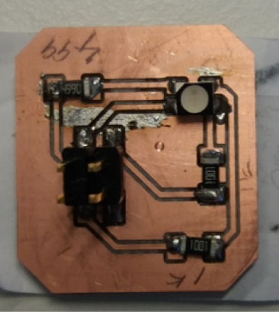
I had problems communicating via the serial port with all the ATtiny44 boards from previous assignments. I did not get a response whenever I programmed the boards via the Arduino IDE to communicate with Processing and there were no errors displayed. Therefore, I decided to connect the RGB LED board from Output devices to an Arduino Uno using Jumper cables. The board just has an RGB LED and current limiting resistors connected to a 2x2 pin header.
Each colour is connected to its own pin and the fourth pin to VCC as the board has a common anode (data sheet). In order to control the LED, each colour is connected to an Arduino pin and VCC is connected to 5V. I connected the board to pins 3, 5 and 6 which are 3 of the 6 PWM pins in Arduino boards with ATmega168 or ATmega328P. Like above, the Arduino was connected to the computer via a USB cable. The image below shows this set up.
I followed these instructions for changing the colour and intensity of an RGB LED according to the colour moused over in the Processing window.
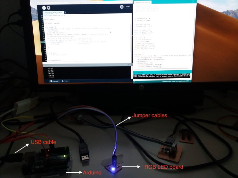 Connecting the RGB LED board to Arduino
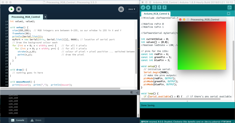
The colour and intensity of the LED change as you move the mouse across the Processing window shown in the image below (the one superimposed on the Arduino window). As the mouse moves, its position (x, y) is printed in Processing’s console. Tow bytes are sent through the line, the first one corresponds to Red and the second corresponds to Green.
 Programming the RGB LED board and testing
And a video showing the result.

For the Processing window, you give it a size (255, 255 the X and Y axes) equivalent to RGB values which are from 0-255 and then with the frameRate() function, you define the number of refresh times per second (30). In the for() loop, the colour of the pixels is defined with the stroke() function and the point() function draws the pixels. In mouseMoved(), values are stored in a byte array and the full array is sent over serial.
void setup() {
  size(255,255);  // RGB integers are between 0-255, so the size of the Processing window is 255 in X and Y
  frameRate(30);  // Specifies the number of frames to be displayed every second ... attempts to refresh per second
  printArray(Serial.list());
  myPort = new Serial(this, "/dev/tty.usbmodem14101", 9600); // location of serial port
  // Draw the background colour wash
  for (int x = 0; x < width; x++) {    // for all X pixels
    for (int y = 0; y < width; y++) {  // for all Y pixels
      stroke(x,y,0);                   // colour of pixel = pixel position ... switched between 0 and 255
      point(x,y);                      // draw the pixel
    }
  }
}

void draw() {
  // nothing goes in here
}

void mouseMoved() {
  print(mouseX);  print(",");  println(mouseY);
  byte out[] = new byte[2];
  out[0] = byte(mouseY);
  out[1] = byte(mouseX);
  //out[2] = byte(mouseY);
  //out[3] = byte(mouseX);
  myPort.write(out);
  //println(out);
}
And in Arduino, you set the pins as output in setup() and in the loop() you read the data coming from serial (the colour and values of the pixel).
void setup() {
  // initialize serial:
  Serial.begin(9600);
  // make the pins outputs:
  pinMode(redPin, OUTPUT);
  pinMode(greenPin, OUTPUT);
  pinMode(bluePin, OUTPUT);
}

void loop() {
  if (Serial.available() > 0) {   // if there's any serial available, read it:
    int incomingValue = Serial.read();
    values[currentValue] = incomingValue;
    currentValue++;
    if(currentValue > 1){
      analogWrite(redPin, values[0]);
      analogWrite(greenPin, values[1]);
      //analogWrite(bluePin, values[2]);
      currentValue = 0;
    }
    else {
      Serial.println("Nothing"); //
      delay(100);
    }
   }
  }
In this case, since the network activity always start after interaction with the user, we do not need a handshake or a preamble. However, it would have been nice to add this handshake before sending mouseY and mouseX (for instance, Neil’s codes always send the sequence 1, 2, 3, 4 before sending any kind of data).
Files
- Arduino - Arduino RGB Control
- Processing - RGB Control
Reflection
This past two weeks have been the slowest so far as I have been unwell. To make matters worse, in this week I could not get Processing to communicate with any of my boards from previous weeks (I am often slow, but in weeks like this one when it is beyond me, then it is a disaster!). Even replicating other examples from the Fab Academy, such as this one for controlling the LED in the hello echo board did not work. I could program the board to blink the LED, but couldn’t control it via Processing. As the boards, at least two of them, worked in the Networking and Communication haven’t yet figure out why the connection with Processing doesn’t work.
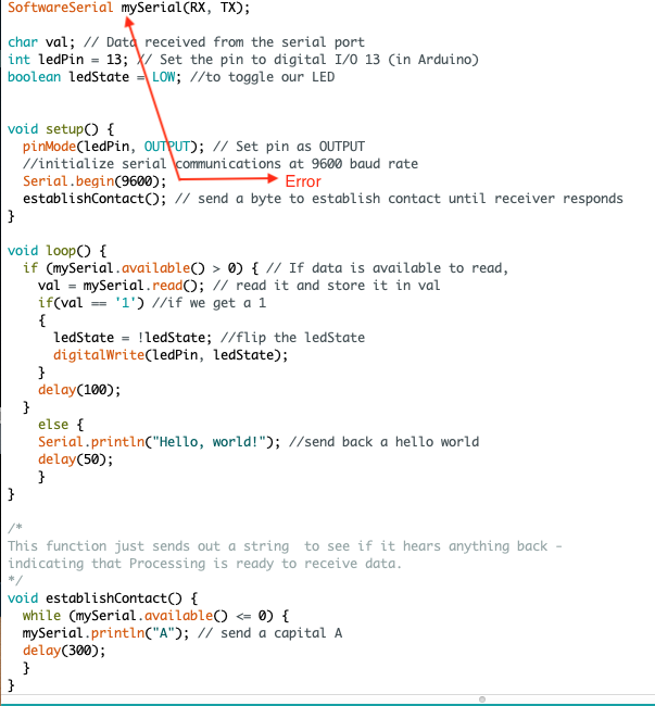
Update: With Ivan’s help, I managed to fix the problem. Turns out I had a small error in the Arduino sketch as shown in the image below (mixing Serial… with mySerial…) that led to the serial communication failure when trying to program my boards (the minor details can be a pain at times!). There are times, though, when serial communication just doesn’t work and a reboot is required. When the Arduino is connected to the computer like above, then it uses the serial port from the UART (Universal Asynchronous Receiver/Transmitter) which is not available in the Tiny’s. SoftwareSerial can still be used with Tiny’s for two-way communication but it should be modified to mySerial in order to work.
A video of Arduino-Processing working with the hello echo board is presented below. Pressing in the processing window turns the LED on or off. After the slight correction, I just connected the board and programmed it as in Embedded programming and some later weeks it worked. In this board, I just replicated Blinking the LED section above.
Processing has good documentation and plenty of online examples, but could not explore it as much as I would have liked to so there is still plenty to learn. Going through a few tutorials helped me to understand the basics of, for example, the coordinate system, colours and serial communication (even though it hasn’t yet worked with any of my boards). When I get it to work will also look at controlling at least two devices (servo motors, LEDs and IR sensors) and later also consider other applications for developing interfaces.
Files
- Hello Echo Board - Connecting Echo Board to Processing
- Processing - Connecting Arduino to Processing