8. Computer controlled machining
Abstract
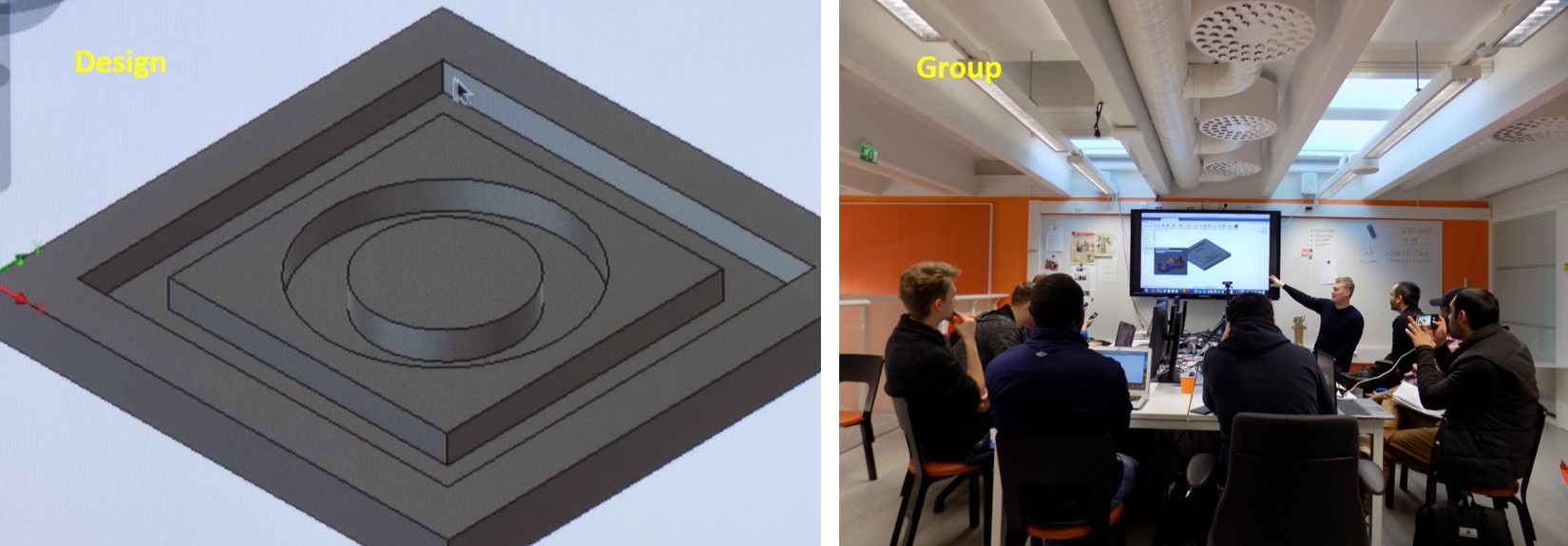
In this week we are started group work together with our local instructor Eino Antikainen. A simple design file for cutting and engraving the wood. We are selected for group work 18 mm thick wood. The first attempt is to learn how the design performs and simulated the design using Fusion 360 and how to get the tool paths in CAM workspace. Followed by how to prepare the machine and cut the model. I am just started to learn the Fusion 360 3D designing. For my assignment, I am planning a simple design which I can easily design in the fusion 360 in a short time. I decided to make a small foot rester table plan to design.
Group Assignment
Test runout, alignment, speed, feed and toolpath for the machine. This week all fab lab Oulu 2019 batch students start to do together due to time-saving. Our instructor helps us to design a simple 3D model, and while preparing the setups for the design, he explained essential points need to be considered.
See the figure below,
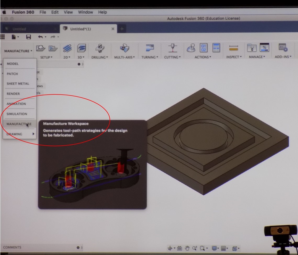
During the design process, the instructor guides us to define the thickness of the board during the extrusion process. Followed by open the design in manufacture workspace. See the figure below,
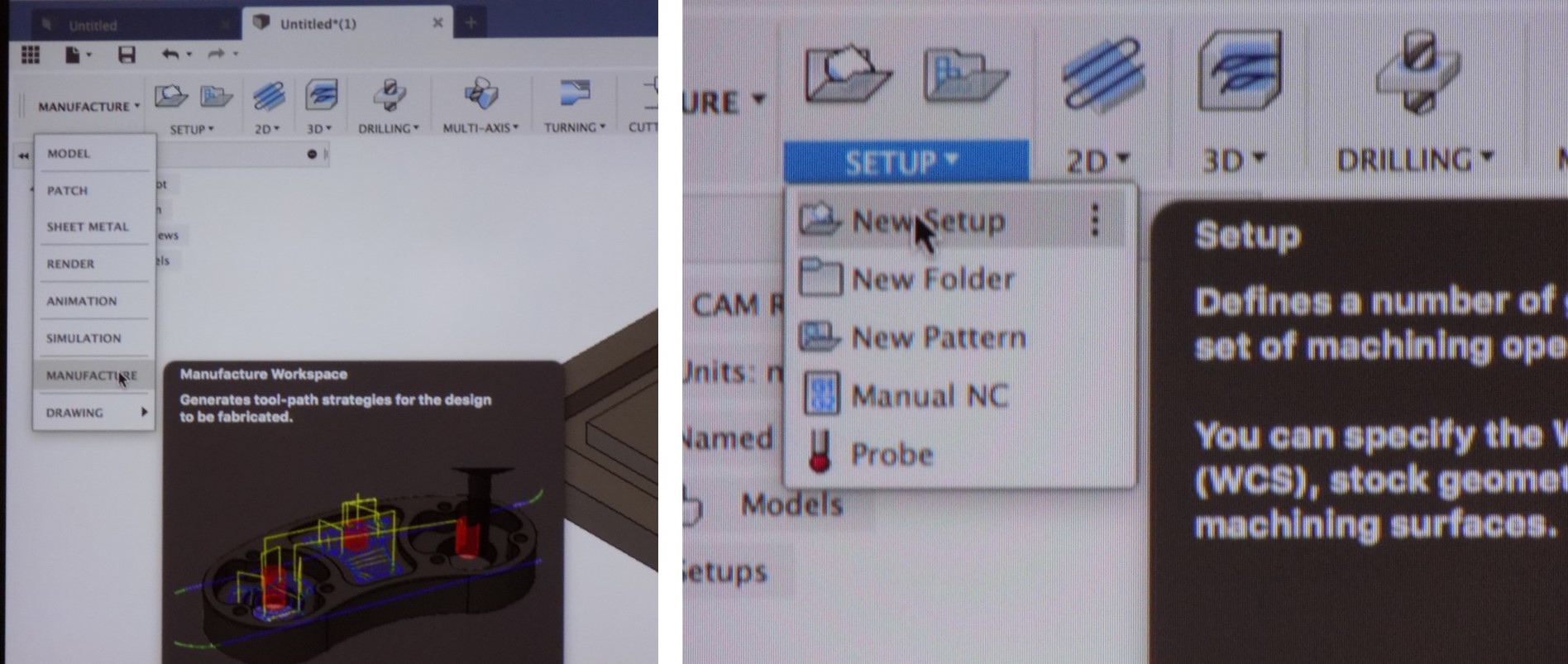
Next step is got to the setup and make a new setup, which opens up a new window as shown in the figure below,
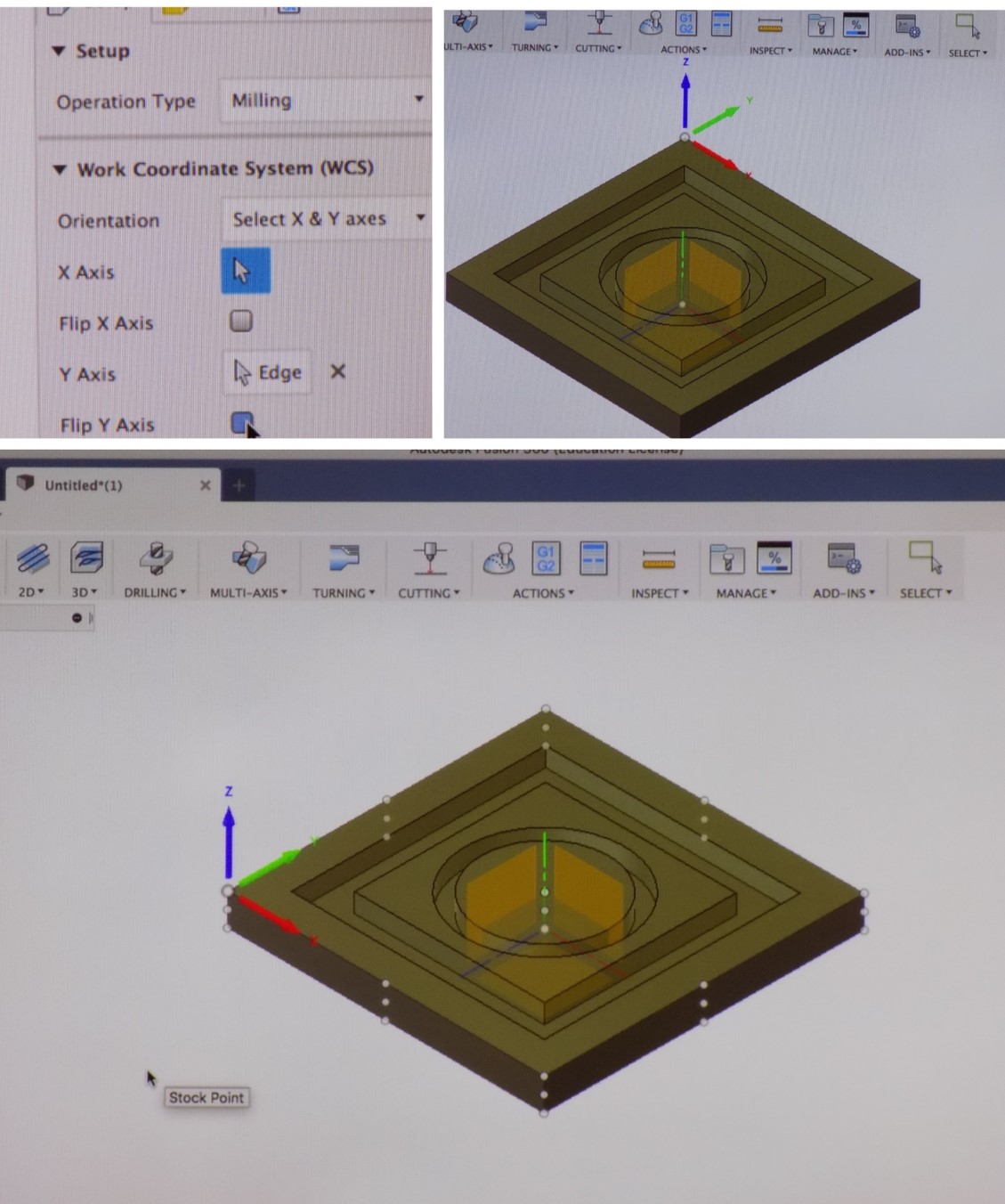
We discuss setup, stock and post process. Finally, we set the stocks point as shown in the below figure,
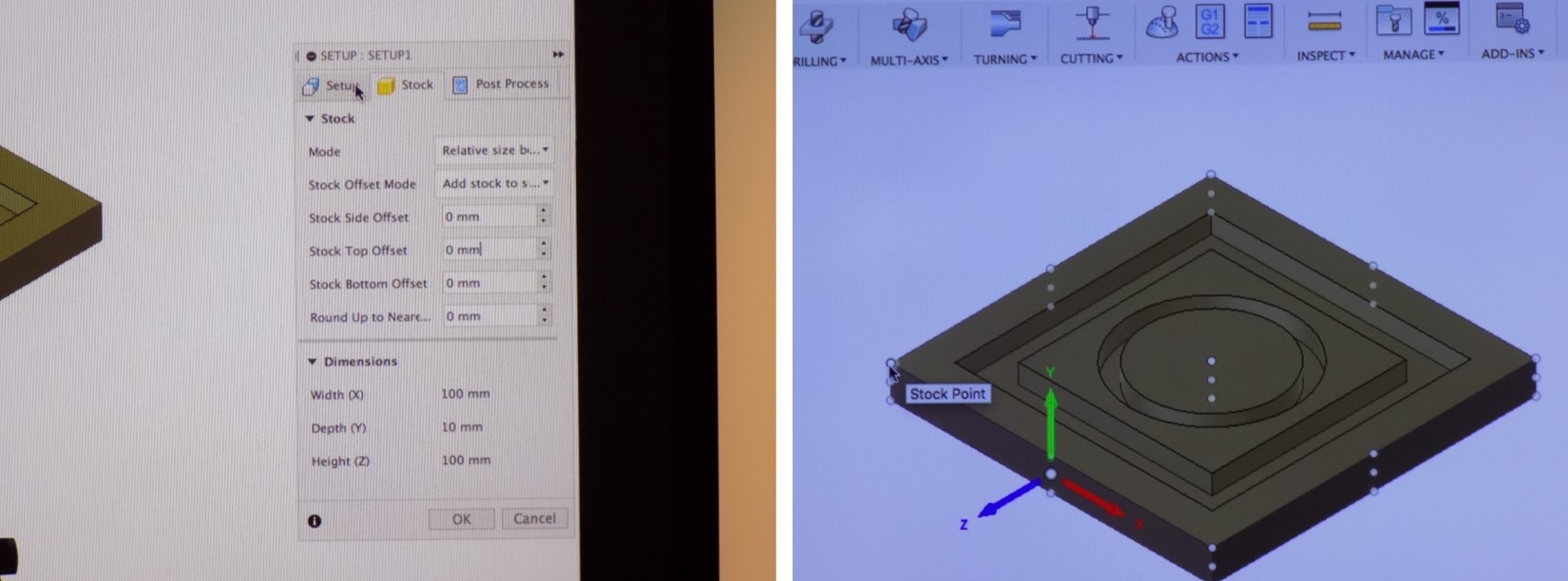
In order to define the cutting direction, we corrected the work coordinate system as XY as shown in the below figure,
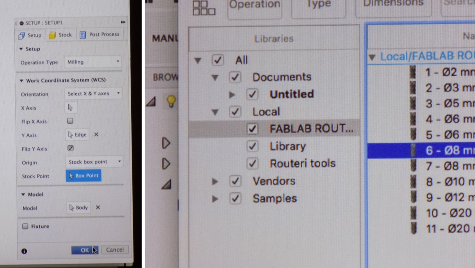
See below figure represent final setup1 and followed by accessing the Oulu fablab library for tool selection; our recommended tool diameter is 8 mm.
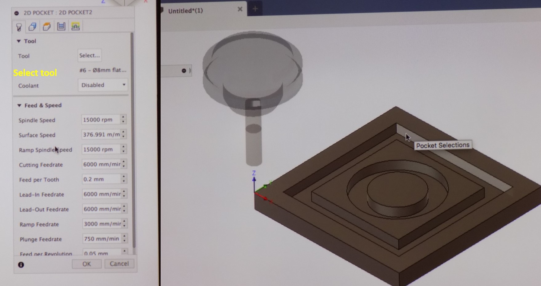
Next step is going to 2D and click 2D pocket, here we can select the tool and see the default speed of the milling. See the figure which presents the milling tool in the set stock point.
Defining the geometry and heights, see the figure below,
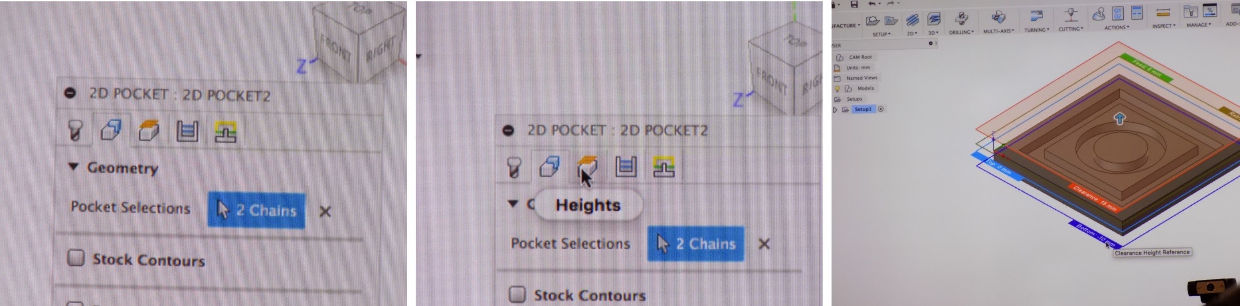
Finally defined 2D pocket 2 file and geometry is shown in the figure,
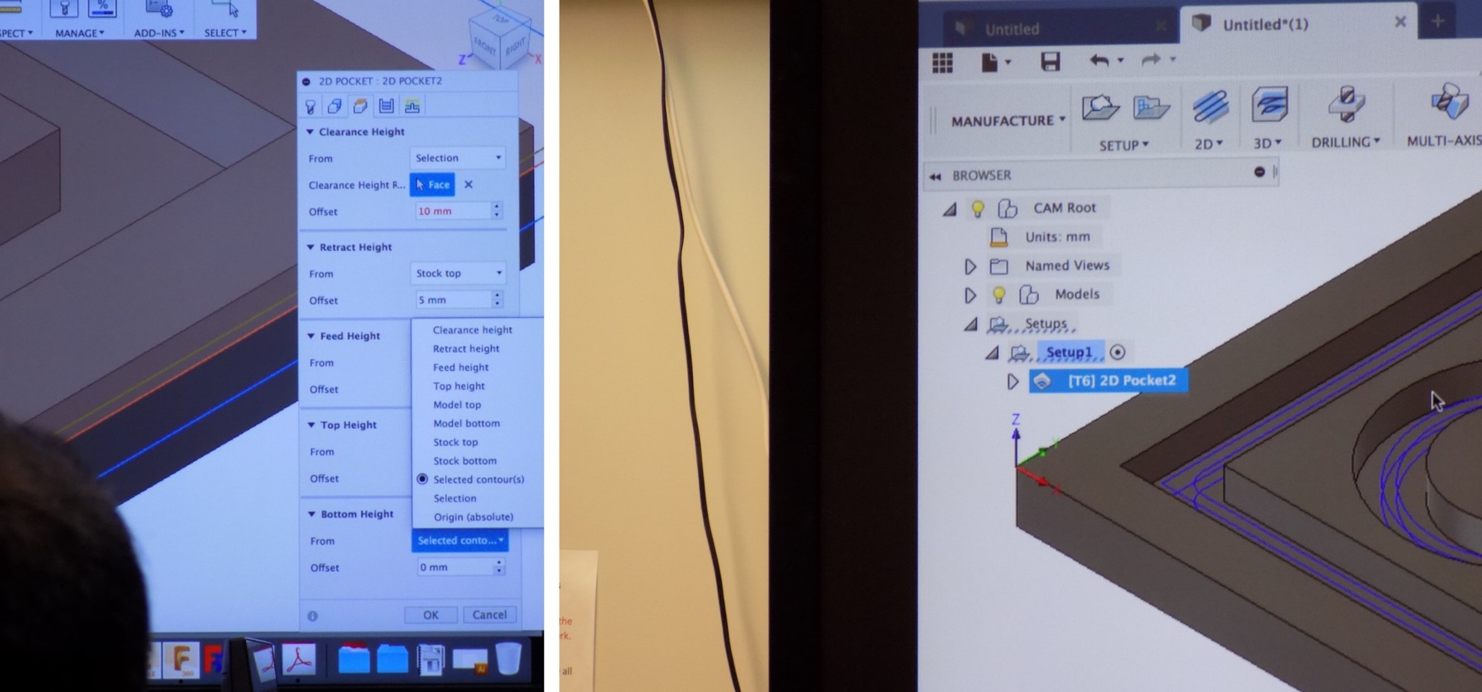
Always check the top height 0 mm, bottom -10 mm which represent the board thickness. See the illustration below,
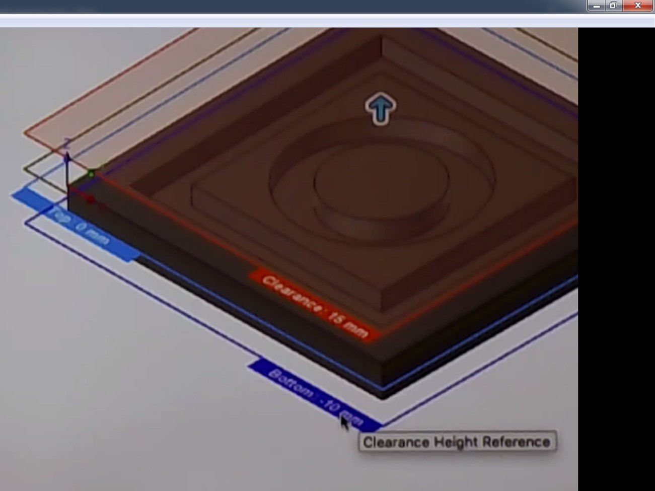
Finally simulated the design in the fusion 360 to see the machine cutting which we defined through the design.
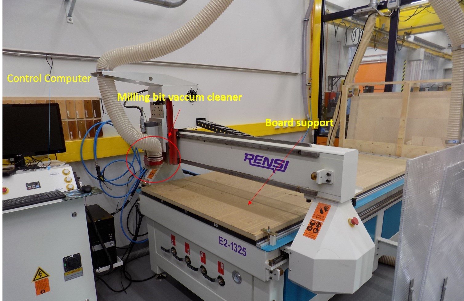
Then we all together move to the CMC milling machine, See the CMC milling machine we have in the Oulu fab lab.
Switch on the system and CMC machine, see the software NcStudio used to interface the CMC machine.
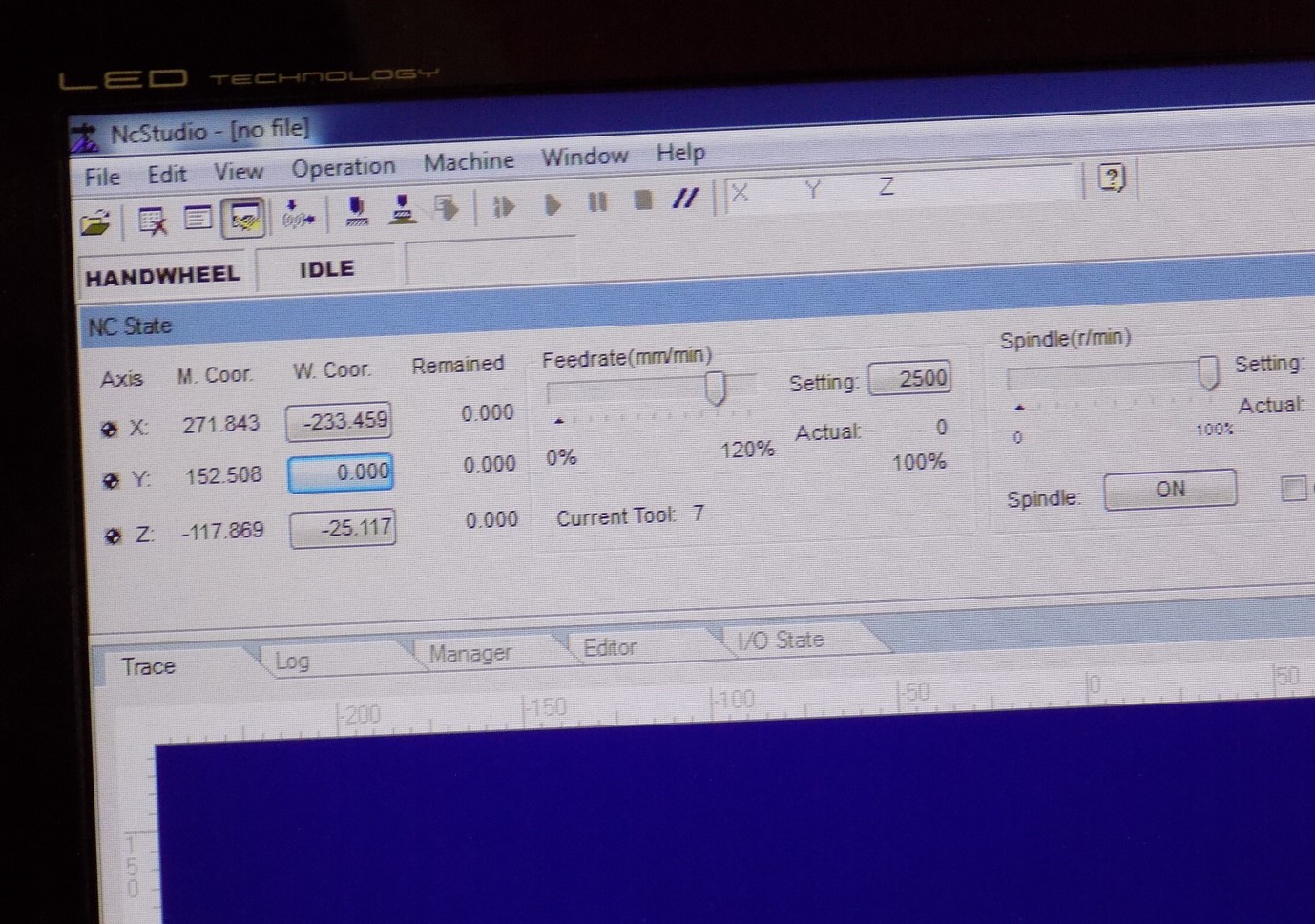
Followed by open the design file that supports CMC machine (NC file), We connected the flat milling bit of size 8 mm, the feed rate was 80% of the maximum 6000 mm/min to 4800 mm/min. Spindle speed is 80% of the maximum 15000 rpm-12000 rpm. Choose the board for cutting and fixed on the table by screwing it perfectly. Set the Z origin both manually and automatic to the learning process, XY position set to zero based on the convenient position considering screw region which avoids during the milling process. See our board, and we started to test using Vernier calliper and screw gauge for the engraved part.
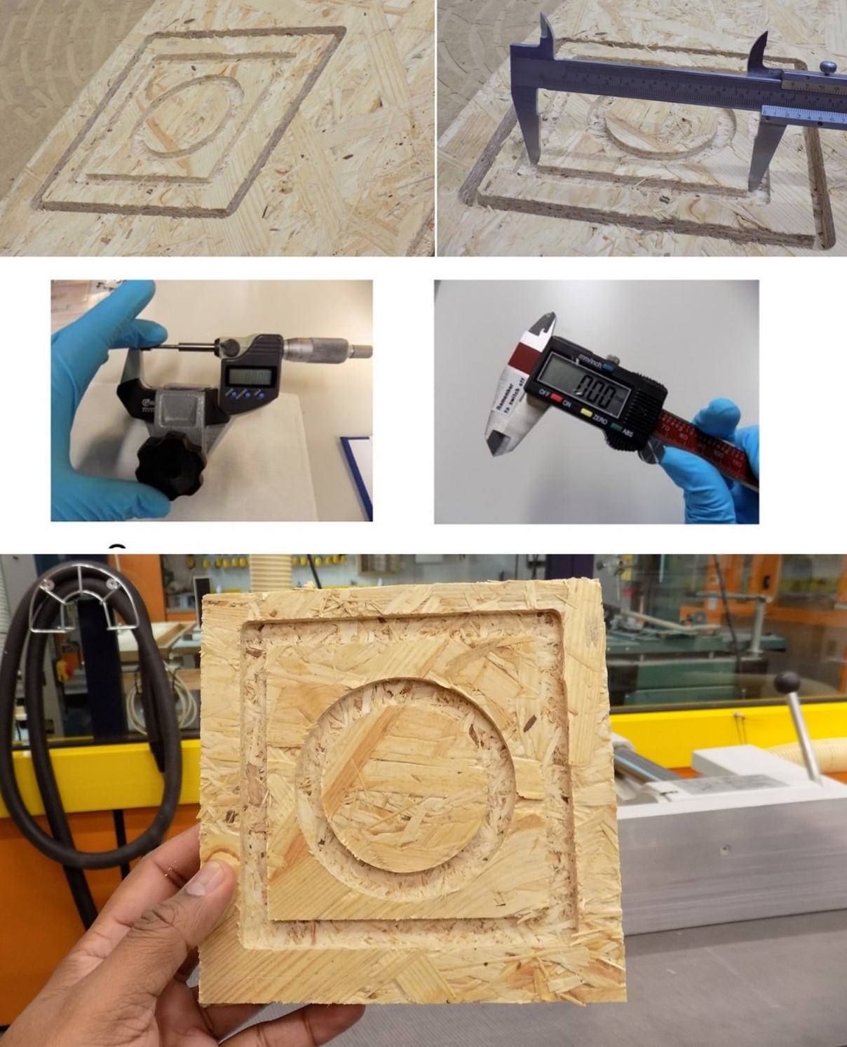
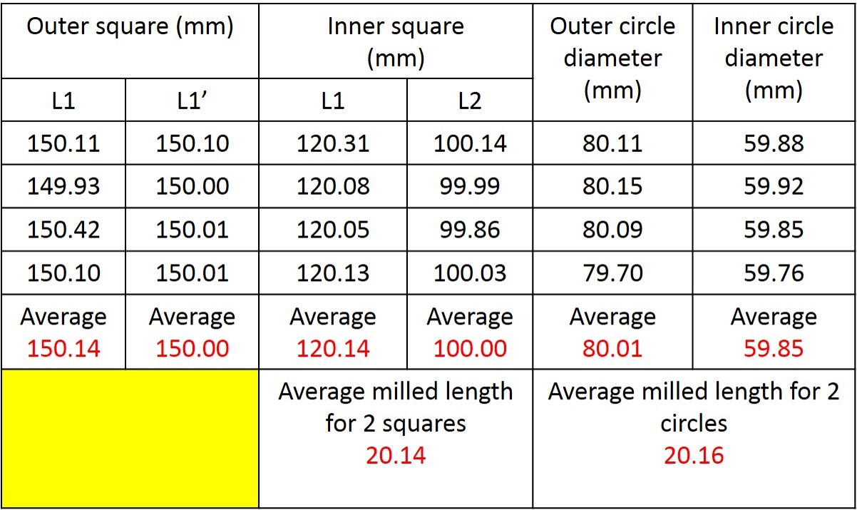
See the detailed measurements in the below table, which present the detailed measurement results of the milled design. We have measured the average milling length for 2 squares is 20.14 mm while the average milling length for the 2 circles is 20.16 mm. Both the values are close, and error is minimal in comparison with the 3D design file.
Similarly, we also documented the engraved area from the square, and circular engrave thickness measured before and after milling using digital screw gauge. See the results and difference in thickness from the square area and the circular area from the below table.
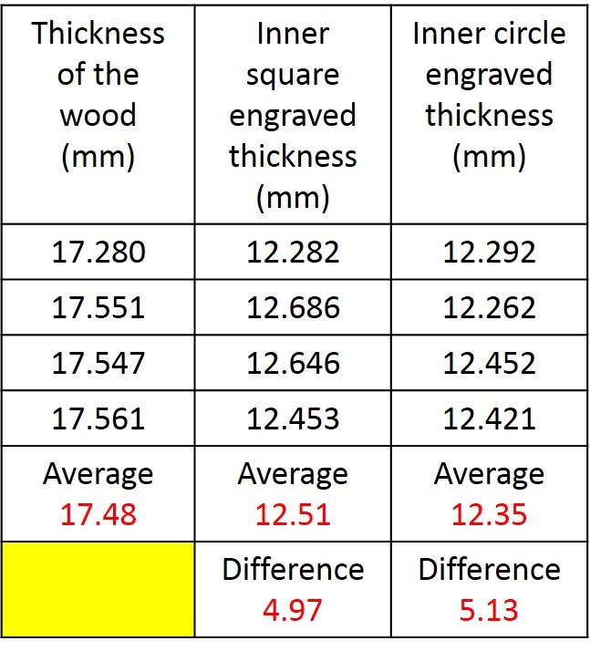
Target design values are, L1 = L1’ = 150 mm, square L1 = 120 mm, L2 = 100 mm, Outer circle diameter = 80 mm and Inner circle diameter = 60 mm and thickness of the wood board used is 18 mm and Engraved area is 5 mm. Here also we observe the difference is very little in comparison with the 3D design.
Individual Assignment
For the individual assignment, I am planned to start design in Fusion 360. I have followed last year documentation to understand how to design 3D models in Fusion 360. It is hard for me to understand the 3D design. I am slowly started to design my foot rester 3D model. I open a fusion 360 and start to save baby foot rester as my project name. Start a blank sketch and assign parametric features of my design. Which includes top and bottom plate with 4 connectors to support the top plate and bottom plate.
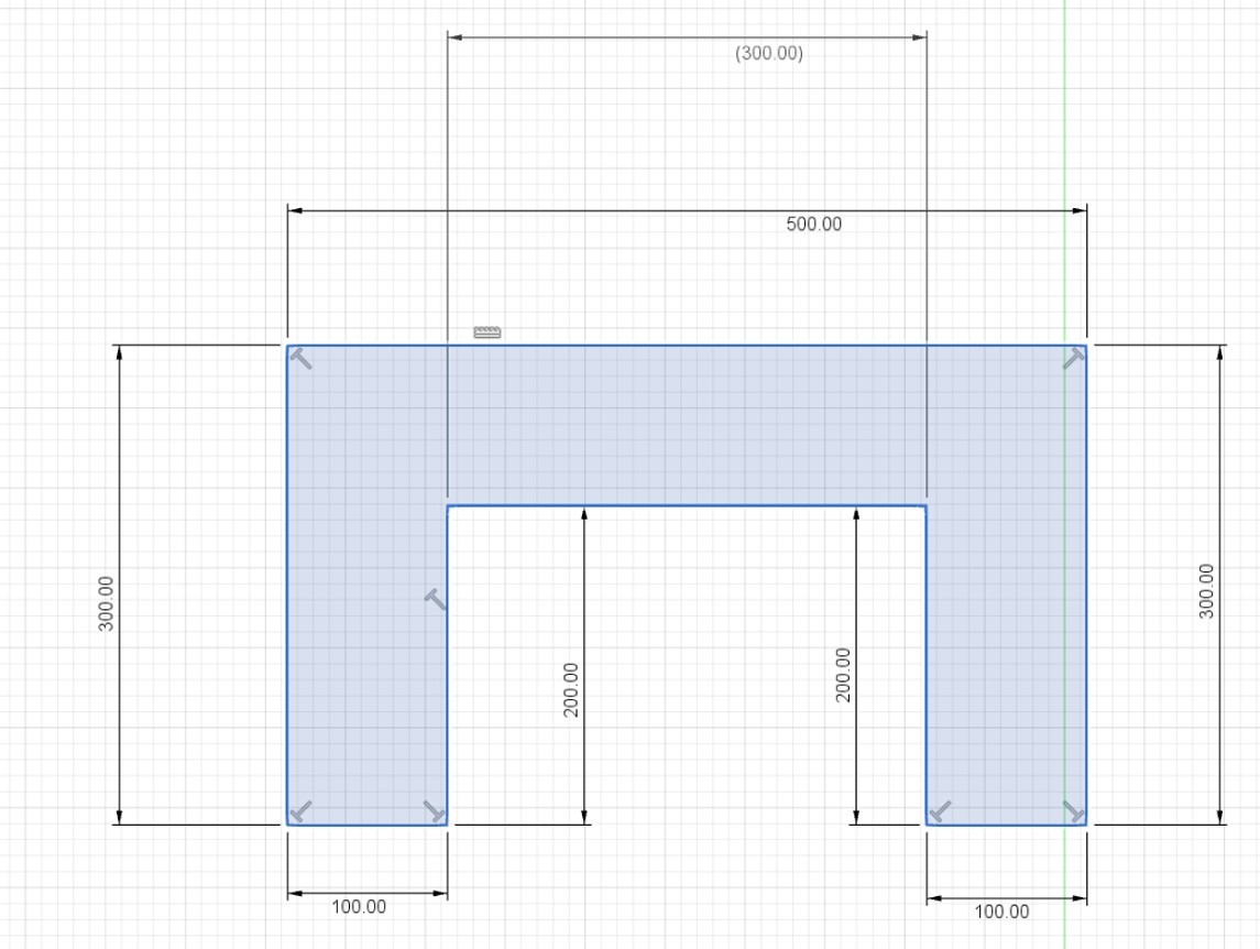
See my initial design sketch is shown in the figure, Top, a bottom plate with dimensions
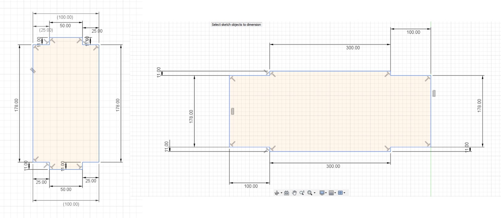
Below figure shows the sketch of legs with dimensions, total 2 number of legs, Front side use a wide plate leg for support, it is also shown in the figure below.
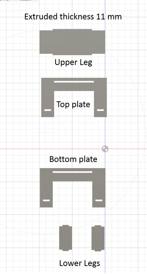
Finally, top, bottom plate and legs small 2 and front flat leg 1 extruded to 11 mm. Finally made a rectangular connection hole through the 11 thickness. After a careful sketch of the top, bottom layers, 2 small legs which support the 10 cm long layer side, 1 big leg which supports longer 50 cm plate with top and bottom press fit connection respectively. See below figure,
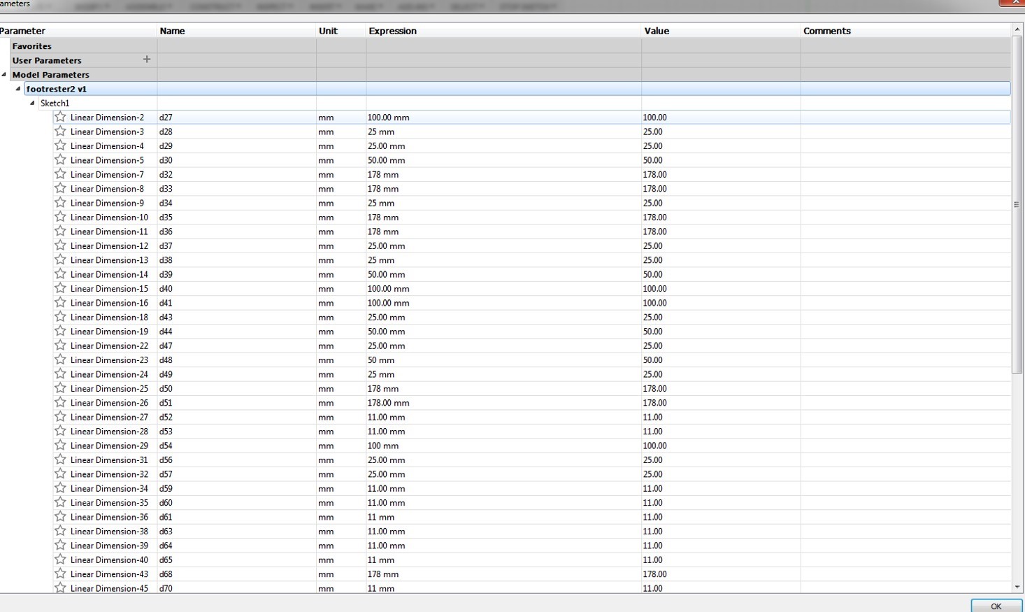
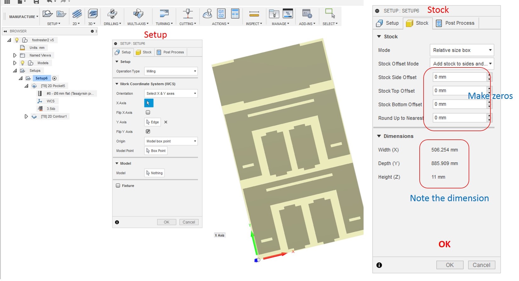
All designs are a little bit aligned to fit in the board for making the NC file which supports the milling machine. The main steps for creating the nc files, open the design in the manufacture workspace to generate tool path strategy for the work. Followed by Setup-orientations in XY axis and stocks-make zeros in the highlighted areas and note the dimensions. Which can be useful in wood materials dimension selection and then press OK. See the figure below.
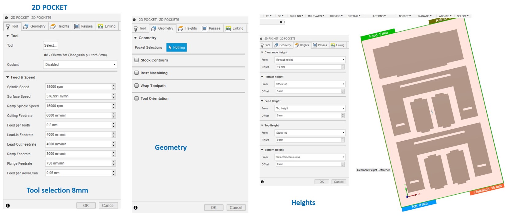
Next step is the 2D pocket assignment, which has tool selection, geometry assignments, heights definition. See the figure below,
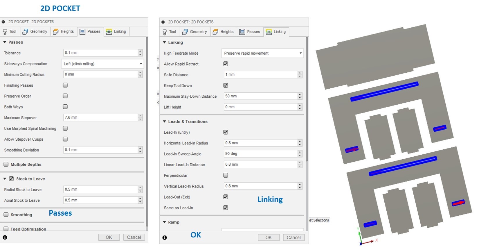
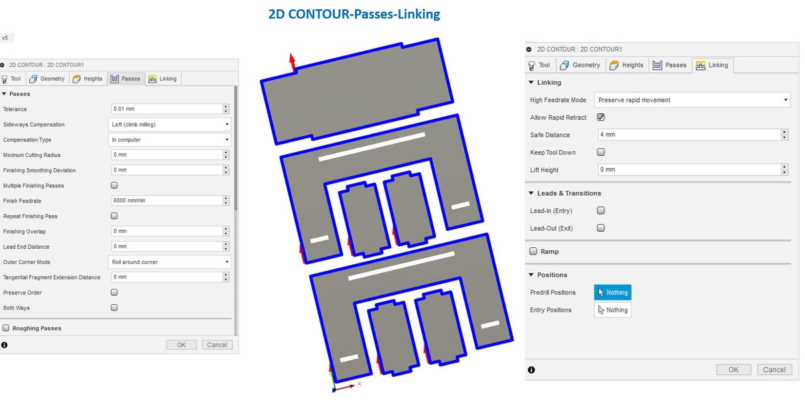
Followed by Passes settings and linking, see the selected 6 pockets in the design
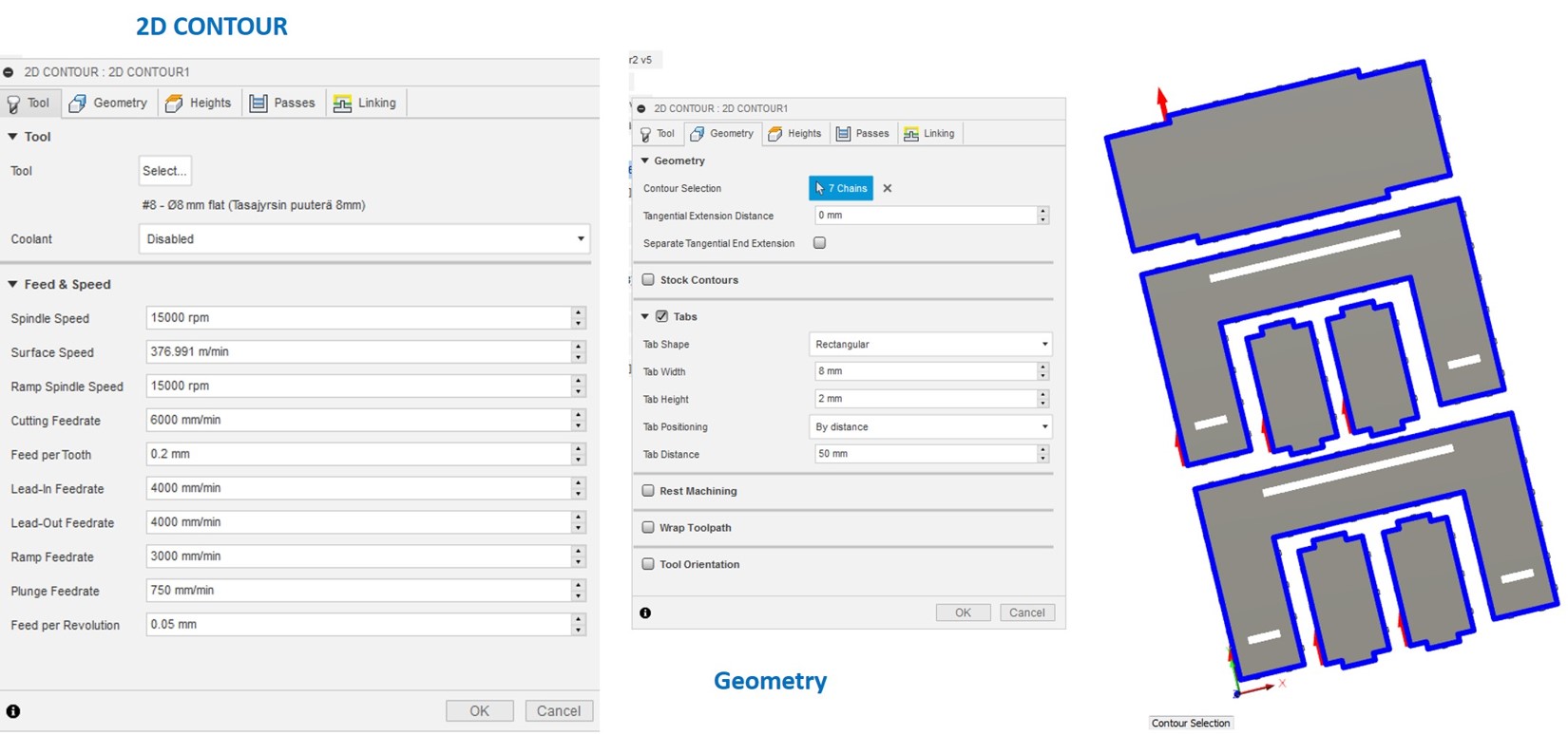
Next step is 2D contour, here also follows the tool selection, select the cutting edges that are in the geometry 7 chains as shown in the figure below,
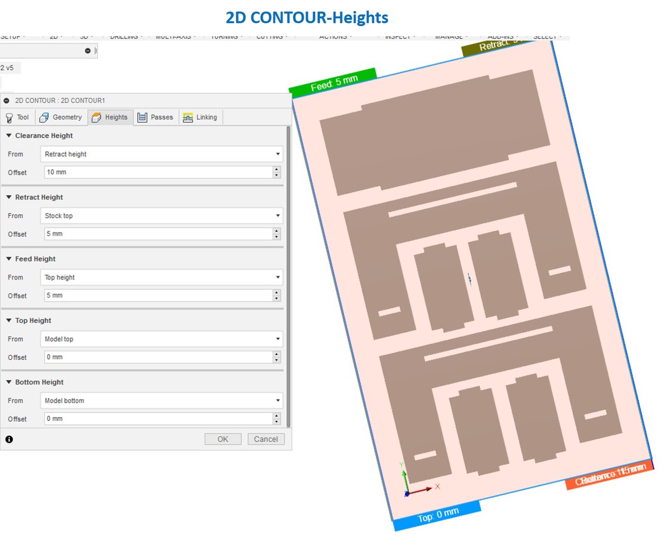
Followed by heights setting-Top height-model top-model bottom. See the height setting view in the below figure,
Similarly, passes and linking settings are also shown in the figure below,
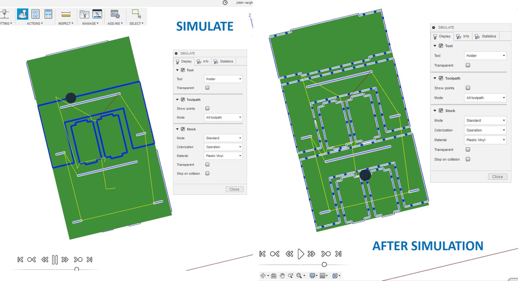
Finally, simulation, starting simulation and final simulated design is also shown in the figure,
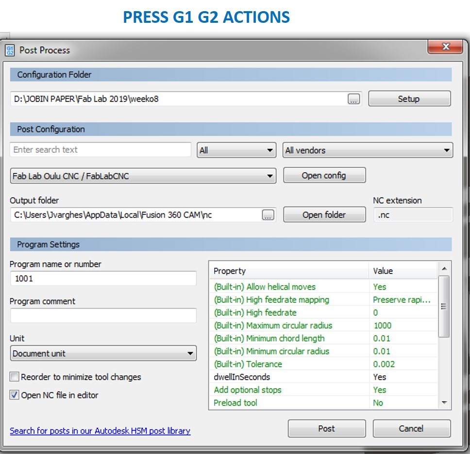
Press G1G2 Action file to save the nc file for cutting, the first set the configuration folder for access the FabLab CNC file. See the nc file creation window in the below figure,
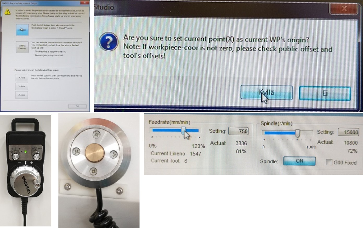
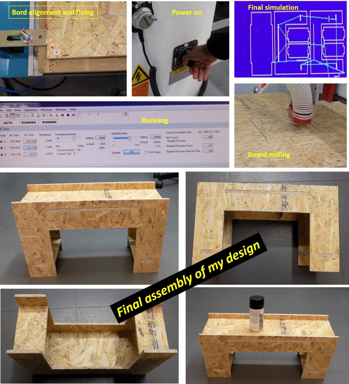
I move to CNC machine for cutting the design with colleagues and local instructor. First I turned on the main switch and power on. Then I set up the table. I attached the OSB board on the table with screws, close to edges so that the machine will not cut the screws. I used 8 mm flat bit that was already attached. Next, I opened the control SW and set the origins. I moved the router with XYZ arrows on the screen. When the bit was in good XY position, I zeroed X and Y as the origin. Next, I calibrated Z axis. I placed the mobile calibrator under the bit and lowered the bit about 10 mm above the calibrator with a hand wheel. Next, I select Operation -> Mobile calibrator. The software did the calibration of the Z origin. After that simulation did successfully.
For my design cutting, I used automatic z-axis setting tool. Cutting started; it takes around 20 minutes. After cutting, I removed all part and finish the edges by carpet knife and combined all the componet with wood glue and set it for 4 hrs. See some pictures of cutting and assembling the final product. Multi-purpose baby footstep table. We can also use a tabletop showcase.
- My design is just a press-fit construction of baby foot rester, I used a saw and sanding little bit for applying the wood adhesive to the slot. However, due to my limited knowledge in designing, I have used a press fit design. I haven’t done dog bone joints in my designing.
The parameters used in the machine are listed below for cutting the wood,
- Feedrate is 85 %,
- Current milling tool is 8 mm flat bit
- Spindle speed is 71 %
- Total time taken: 20 minutes
Additions
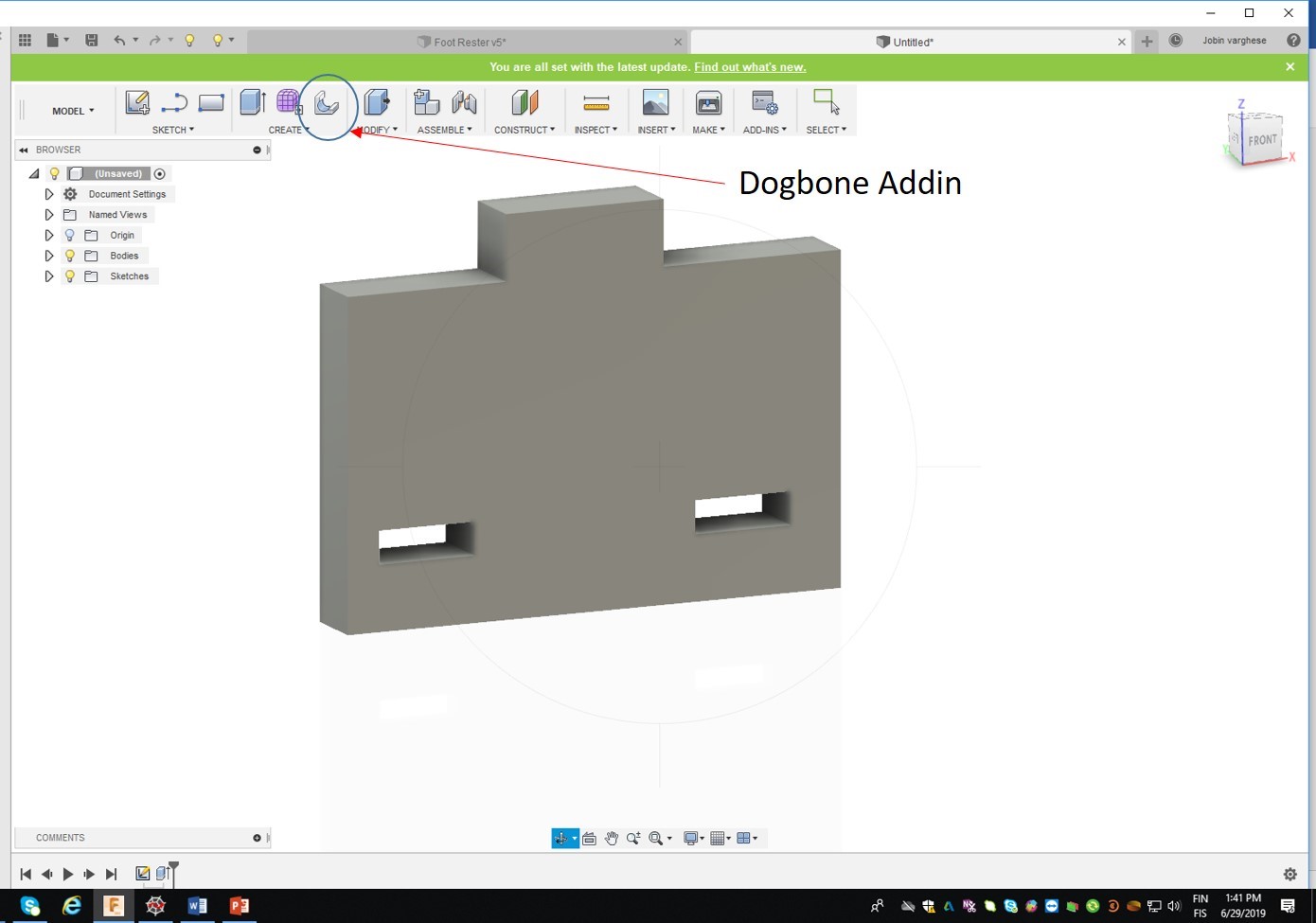
To understand the dog bone design using Fusion 360. I have learned something from Dogbone Gadgets. I have found an interesting video about how to do the dog bone structure using fusion 360. I follow the instructions and install the add-in. Further, I have designed a simple structure with 2 rectangular slots and one tab to create a dogbone structure in the design. See the dog bone addin and simple structure designed before dog bone creation.
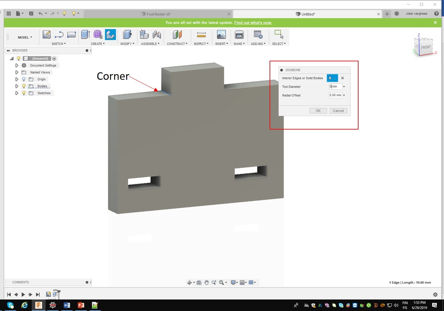
Dogbone structure is created by selecting the corner and clicks the dogbone icon, which opens a window to add diameter, I added 5 mm to both the tabs and click ok to create dogbone structure on both corners of the tab. See the steps in the below figure,
See the final picture below shows the design with dogbone structure,
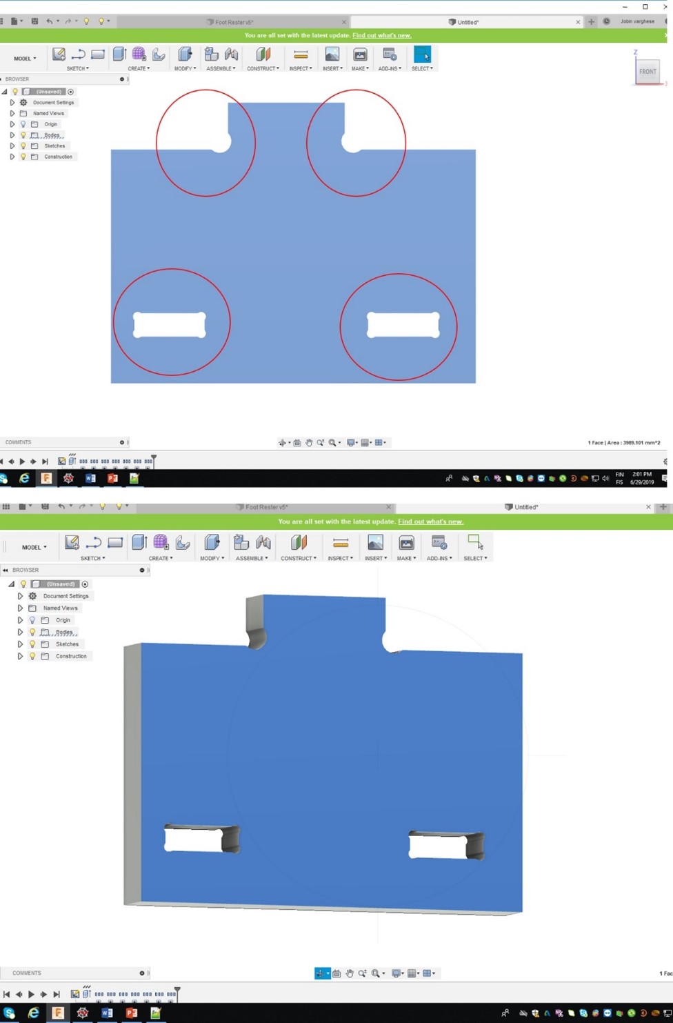
Dogbone structure in the design is used to overcut into a corner when the application of the part you are making needs to fit tightly with another. When cutting out internal corners on a CNC you are left with a round corner due to the round tool you have used; you would need to manually finish off each of these corners with a sanding file to remove the rounded corner. With dogbone structure, you can use the CNC to overcut into these corners by the radius of the tool so that any mating material will be able to slot into place. This method is great for concealed joints, where it will not affect the finish of the product. The above is an example of creating the dogbone structure in the design using CAD tool.
Summary
In the beginning, I am very much afraid to start my assignment due to difficulties in using fusion 360 first time. I need to make footstep for my son. I drew a sketch using paper and pensile and started to draw it in the fusion 360. Many difficulties I faced due to less knowledge in the design environment. Finally, I am thrilled to see my design in the form of a product. Group assignment, help me to start my design and fabrication much easier.