Final Project
Motivation Towards BiEn-HARVESTER
The motivation and idea of my final project is energy and health. To be medically fit and healthy, you need to be physically energetic. Consistent physical activity can help protect you from serious diseases such as obesity, heart disease, cancer, mental illness, diabetes and arthritis. Riding your bicycle regularly is one of the best ways to reduce your risk of health problems associated with a sedentary lifestyle. Cycling is a healthy, low-impact exercise that can be enjoyed by people of all ages, from young children to older adults. It is also fun, cheap and good for the environment.
Another aspect of my project is Energy. Energy is an essential part of our daily lives. We use energy to heat and cool our homes, schools and businesses. We use energy for lights and appliances. Energy makes our vehicles go, planes fly, boats sail, and machines run. All living things need energy too. Plants use light from the sun to grow. Animals and people eat the plants and use the energy that was stored. Food is fuel for our bodies’ energy needs like muscle power. We also use our bodies to make heat energy. When you have been running or working hard, your body produces heat energy. When you wear clothing like a jacket in the winter, it holds in that heat energy and keeps you warm. Also, the increasing population of low power electronic gadgets demands more and more energy. I want to club these all ideas to make a unique and easy solution which can afford to everyone. In my project, I integrate bicycling energy to store it for low power electronic gadgets. In addition to this, I will display the speed of the bicycle in the LCD panel. Hall sensor based magnetic switch used for the detection of the speed of the bicycle.
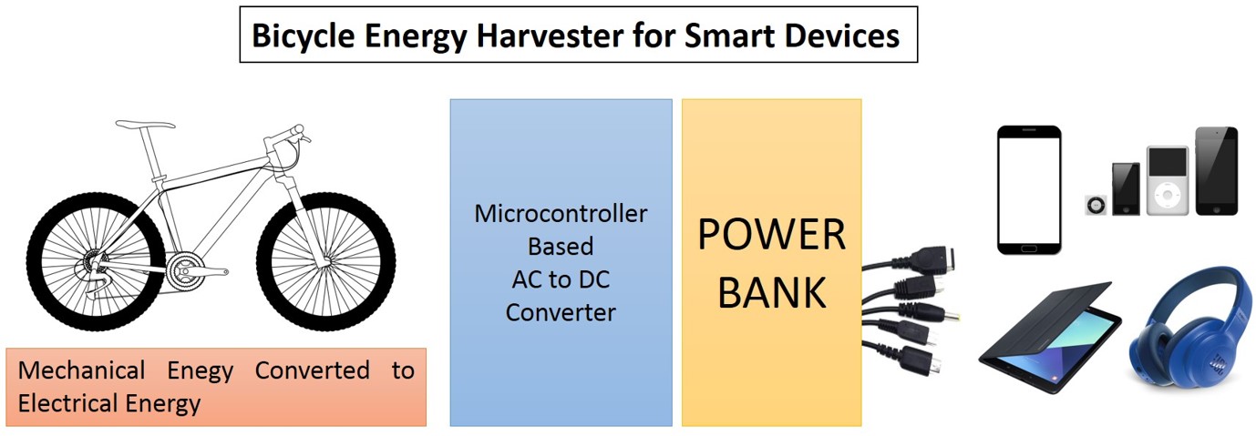
Worldwide, the number of bicycle lists are increased tremendously as health seek, eco-friendly and cost-effective mode of transportation. I am cycling every day around 5-10 km by pedalling force is applied approximately 21.68 N for achieving 30.4 kph or more. Finland has a wide bicycle route nearly 72 marked national cycle routes and many bicycle riders. My idea is an effective way to harvest energy from bicycle dynamo to a power bank. The project describes developing an energy harvesting from bicycle riding for our day today smart devices. The present plan is an attempt to establish an energy harvester module for smart devices power sources. Below figure present a brief idea about my final project,
List of requirements
- Bicycle
- Commercial bicycle dynamo generator
- Electronic parts (PCB, Power supply, Microcontroller, LCD display, USB charging port)
- Acrylic press fit box for project packing
- 3D printed package for electronics
- Power bank
- Connectors (USB)
Current and Previous Work in Bicycle Projects
I have found there are several bicycle energy project during google search, I have made a detailed project survey on bicycle based energy projects. I gather most of the information from all the projects in google search, fab lab projects and made a list which is listed below,
- Commercial Energy Harvester KIT
- JAY_2019 Solar Powered Bike
- Bike Battery tracker_2019FAB LAB
- Pressure Sensing Pedals
- Haptic Navigation Bicycle Handlebars
- 48V Electric Flat Tracker
- Speedometer_2017 Fablab
Electronic Circuit Design and Fabrication
I have used my design files and fabrication for the Input and Output devices. In my final project, I have used my input device hall sensor for detecting the bicycle speed. Similarly, I have used output week LCD for the speedometer display. In the final project, I combine these input and output devices in a single board with changes only done with programming.
See the images of the final project PCB board with all component soldered designed and fabricated.

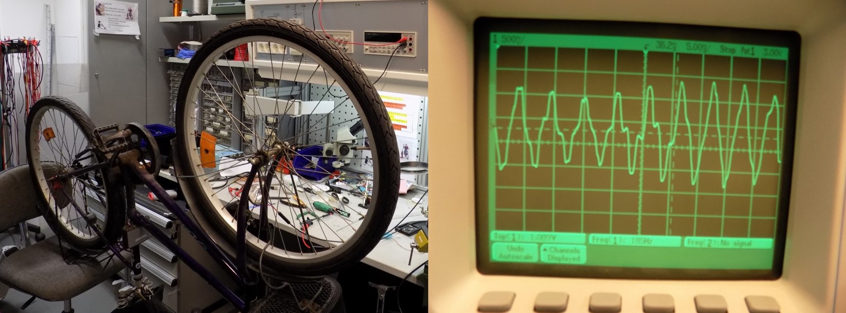
My project electronic circuit fabrication is done with Eagle (schematic and board). I used Roland PCB milling machine for both hall sensor and LCD board. I also develop AC to DC voltage converter by conventional bridge rectifier and voltage regulations for 5 V with minimum voltage dropout. Also made a separate PCB for hall sensor. My final project electronic boards were already done in my Week 11 and week 12 assignments. Both LCD and Hall Sensor working perfectly. For the power supply circuit fabrication, I take long time trial and error methods. I have made a conventional way to connect shortkey diode based bridge rectifier with filter capacitor and regulator available in the Fablab Oulu. Some of the initial testing are shown below, that is AC dynamo output with oscilloscope, its shows the expected voltage level of 6V (AC) and 3 Watts power average.
I used RB-See-266 Bicycle Dynamo. It has output rating based on constant-resistance load (18 ohms) are
- 5 km/h-output power of 0.45 W-output voltage of 2.45 V, output current of 0.115 A
- 15 km/h-output power of 1.89 W-output voltage of 5.78 V, output current of 0.325 A
- 30 km/h-output power of 3.21 W-output voltage of 7.23 V, output current of 0.435 A
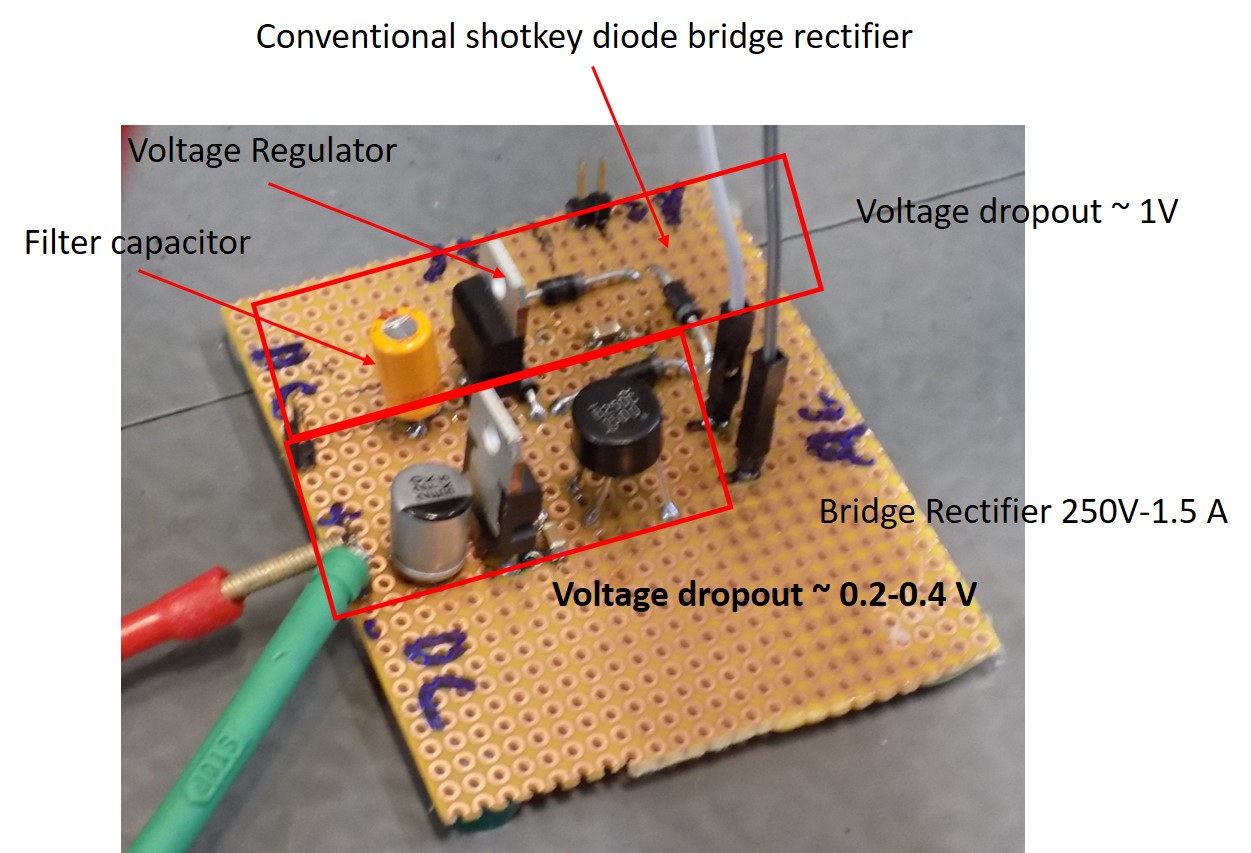
Hence, I decided to use low voltage drop regulator for my bicycle project. See the fabricated regulator board for my final project. I compare the conventional shortkey diode based bridge rectifier and bridge rectifier pack with difference voltage regulator based on its low voltage dropout. Finally, I optimized bridge package with voltage regulator L4940V5. See the board with two type of rectifier for the optimization.
Programming
Hall Sensor
Program done in week 11. For the final project, I used one board for LCD and Hall Sensor. I used Attiny 44A microcontroller for both input and output devices
LCD
Program done in week 12. For the final project, I used one board for LCD and Hall Sensor. I used Attiny 44A microcontroller for both input and output devices
Speedometer
In my final project, one part is harvested energy is used for speedometer. Initially, I faced several issued when both the codes are combined. The major problem is limited memory of Attiny44. I have discussed with our local instructor and finally we made a code for both hall sensor and LCD in a single board that developed in output week. Final code is shown below with explanations in the sting
/*
  Attiny44 Speedometer
  by Cesare Brizio | CC by-sa-nc// Modified by Jobin Varghese
  this sketch is in the public domain

  Version 2.0 - 17 jun 2019
  ------------------------------
  The implementation is relatively rough:
  - wheel circumference has to be hard-coded
  - an attempt at debouncing has been made both at ohysical and software
    level - to no avail. Will be revised soon.
  A few more details here:
  http://www.cesarebrizio.it/Arduino/Speedometer.html

  Modified from an original by John Boxall
  Example 37.3 – Basic speedometer using millis();
  http://tronixstuff.com/tutorials > chapter 37
  John Boxall | CC by-sa-nc

  Hardware – you will need a sensor. For example – a reed switch and magnet.
  Consider the reed switch to be a normally-open button, and connect as usual
  with a pull-down resistor.

  ==========================
  The circuit for LCD board
  (HD4770 compatible display)
  4-wire dialogue
  ==========================
 * LCD RS pin to digital pin 5
 * LCD Enable pin to digital pin 4
 * LCD D11 pin to digital pin 3
 * LCD D12 pin to digital pin 2
 * LCD D13 pin to digital pin 1
 * LCD D14 pin to digital pin 0
 * LCD R/W pin to ground
 * LCD VSS pin to ground
 * LCD VCC pin to 5V
 * 10K resistor:
 * ends to +5V and ground
 * wiper to LCD VO pin (pin 3)

*/
// include the library code:
#include <LiquidCrystal.h>
// initialize the library with the numbers of the interface pins
const int rs = 5, en = 4, d11 = 3, d12 = 2, d13 = 1, d14 = 0;
LiquidCrystal lcd(rs, en, d11, d12, d13, d14);
 float start, finished;
float elapsed, time;
float circMetric=2.093; // wheel circumference (in meters)
float circImperial; // using 1 kilometer = 0.621371192 miles
float speedk, speedm;    // holds calculated speed vales in metric and imperial

void setup()
{
  // convert metric to imperial for MPH calculations
  circImperial=circMetric*.62137;
  // the syntax with digitalPinToInterrupt should allow portability
  //among different Arduino models - see https://www.arduino.cc/reference/en/language/functions/external-interrupts/attachinterrupt/
  attachInterrupt(digitalPinToInterrupt(8), speedCalc, RISING); // interrupt called when sensors sends digital 2 high (every wheel rotation)
  //attachInterrupt(0, speedCalc, RISING); // interrupt called when sensors sends digital 2 high (every wheel rotation)

  //start now (it will be reset by the interrupt after calculating revolution time)
  start=millis();

  // set up the LCD's number of columns and rows:
  lcd.begin(16, 2);

  // Print a transitory message to the LCD.
  lcd.print("  Bi_SPEED");
 // delay(5000); //just to allow you to read the initialization message

 }

void speedCalc()
{
  //Function called by the interrupt

  if((millis()-start)>100) // 100 millisec debounce
    {
    //calculate elapsed
    elapsed=millis()-start;

    //reset start
    start=millis();

    //calculate speed in km/h
    speedk=(3600*circMetric)/elapsed;

    //calculate speed in mph
    speedm=(3600*circImperial)/elapsed;
    }
}
 void loop()
{
  // The loop will be interrupted by the sensor each time the
  // magnet passes near the sensor, in other words once per revolution

  // Top line in the 16 char, 2 lines display - speed data
  lcd.setCursor(0,1);
   lcd.setCursor(0,1);
  lcd.print(int(speedk));
  lcd.print(" km/h ");
 lcd.print(int(speedm));
 lcd.print(" MPH ");
  }
Trials
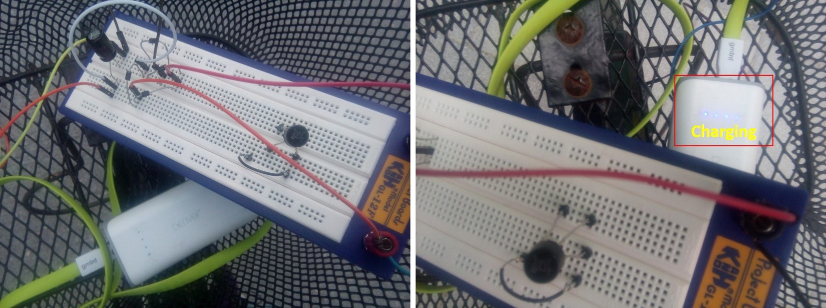
I have done several trial before reaching the final projects, test trials images are shown below, Power bank charging test using breadboard measurement as shown below, after several trials for changing the filter capacitor, regulator, finally I chosen bridge package with L4940 regulator which has low dropout voltage,
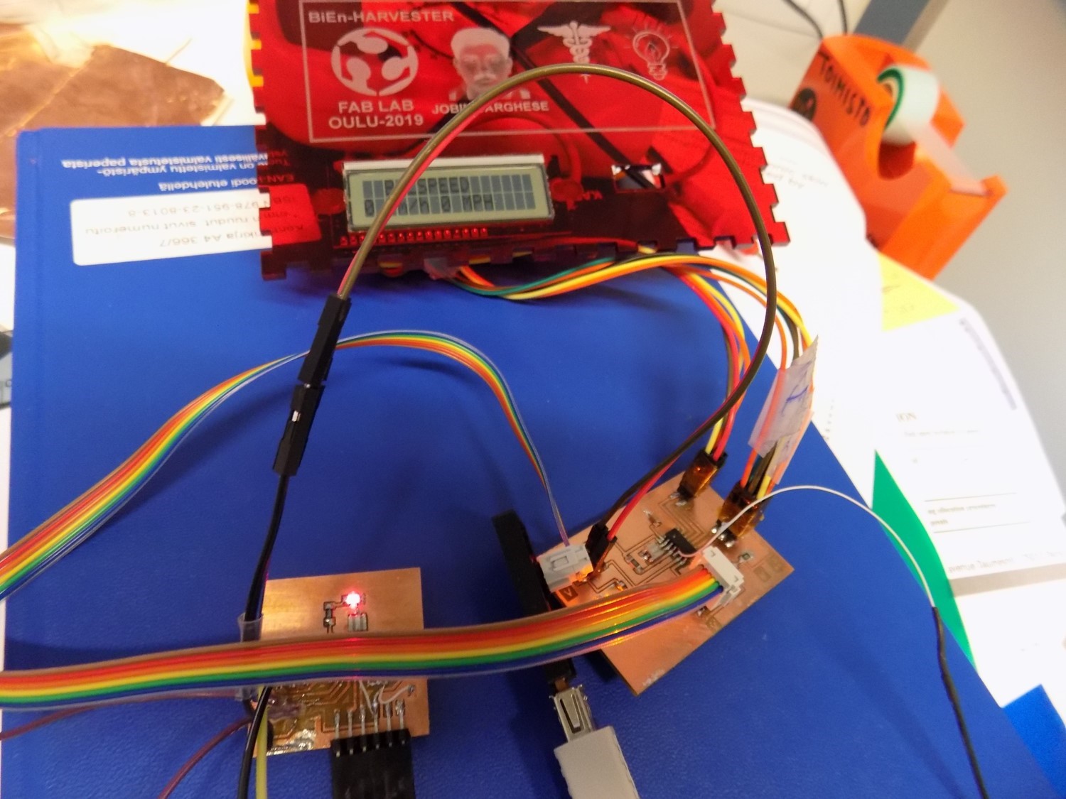
The final program after burning the code, LCD output with Hall Effect sensor as shown in below figure,
Package Design and Fabrication
I have used 2D and 3D design modules based on my final project requirements. I have designed a Pressfit 3 mm acrylic box for my final project. I used laser cutting and engraving as a subtractive technique in my final project. While 3D printed using Formlab Printer for circuit board spacer 50 x 50 mm with or without equally spaced holes for the arranging the PCB board in the final project box. Also, I have done design and 3D print using FORTUS 380MC a small case for a hall sensor to attach the bicycle. 3D printing is an example of an additive manufacturing technique used in my final project.
Simple 3D printed PLA based spacer for final project packing for separating the PCB board in the box. A spacer for hall sensor are also designed using Fusion 360, the detailed design files screenshot are given below (circuit spacer 3D printed with PLA using form Lab printer),

Another 3D printed part for hall sensor support are shown below

Laser cutting and laser engraving is utilized for developing a Pressfit box for the final project. Total lasering time taken is 10 minutes for all parts. 3 mm red color acrylic board used for the full package for the project. I inserted several holes (0.5 cm) in the sides, top, bottom, front and back. Also provided space for LCD and USB female port and Power bank in the box. See the Inkscape designed box in the below figure for the final project,

Finally all the parts assembled together and connections are made, See the inside view, I used hot glue gun used for attaching the parts such as LCD, USB, PCB board, Regulator board, Hall sensor etc, Of course, I am not good in packing things, see my box inside view,

All Design files
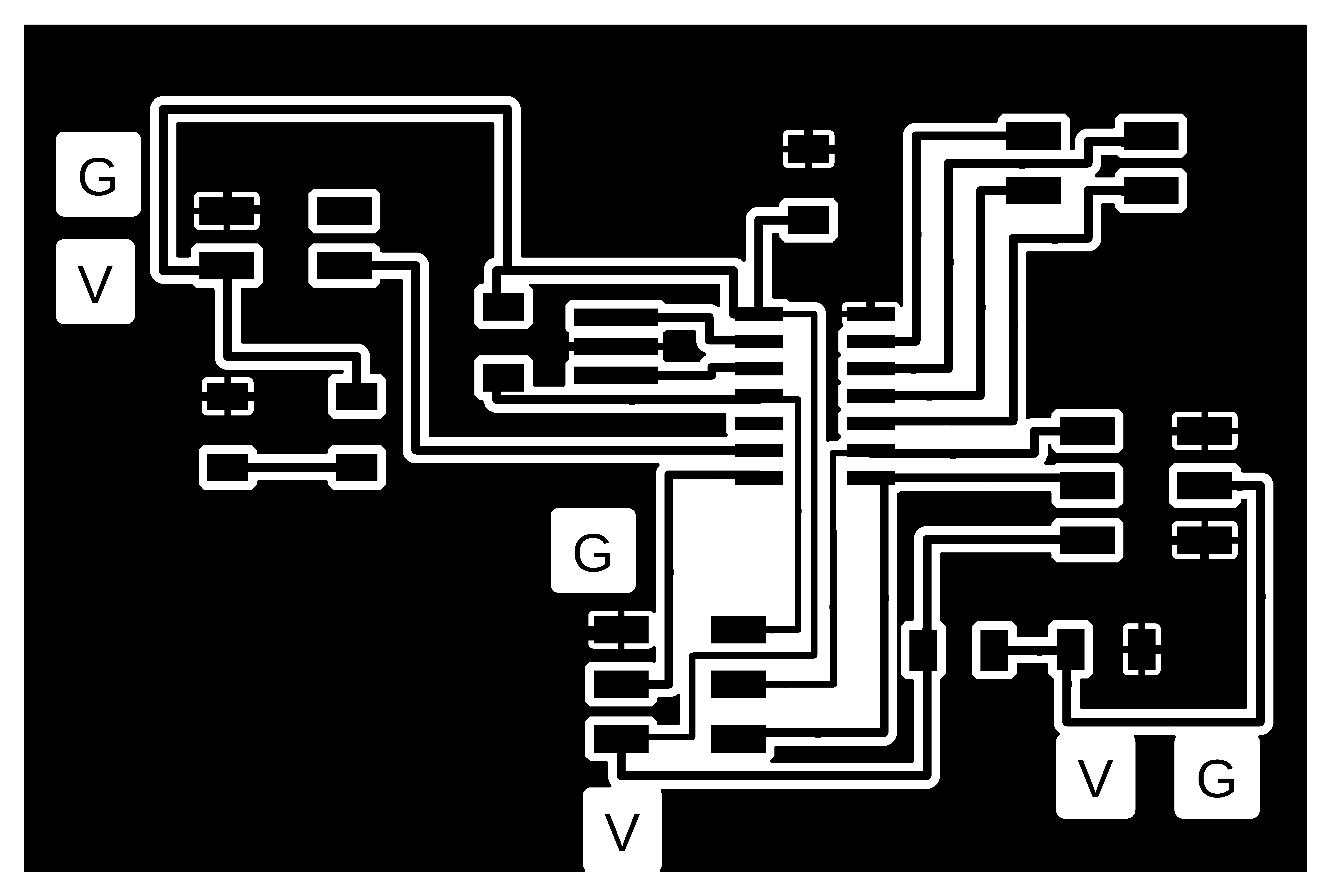
- LCD Board
- LCD Schematic
- LCD board trace PNG file
- LCD board outline PNG file
- LCD board trace RML file
- LCD board outline RML file
- PCB Support 3D Printing f3D file
- PCB Support 3D Printing stl file
- Press Fit Box SVG File
- Press Fit Box PDF File
- 3D Printing Hall Sensor Package F3D File
- 3D Printing Hall Sensor Package STL File
- Final Code Speedometer
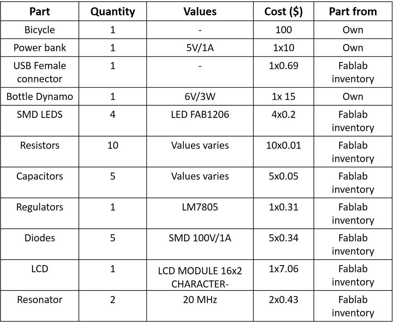
Project Cost
An approximate estimation of my final project is shown in below table, which is excluded from 3D printing, Laser cutting and PCB milling and final assembly. Overall cost of my final project is 30 euro, I excluded the Bicycle, Power Bank and Dynamo from the list.
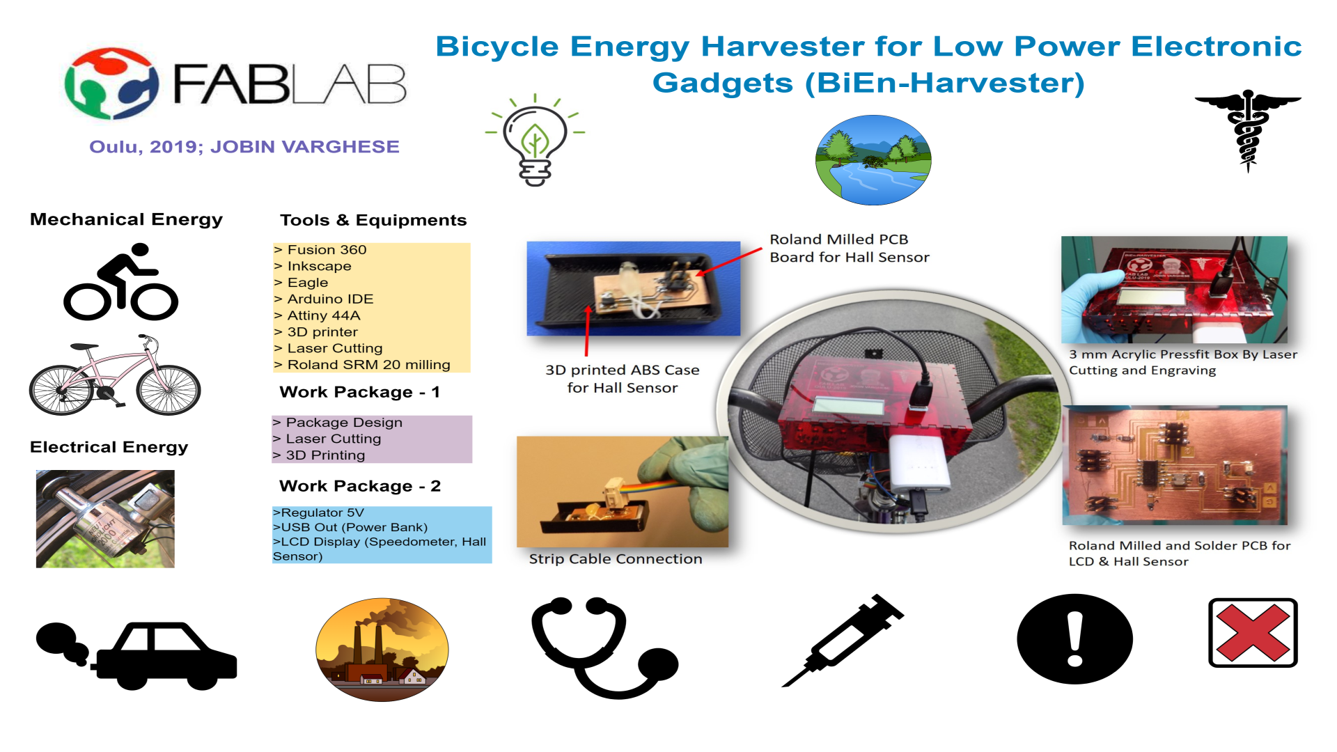
Final Project Slide
Final Project Video
License
Licenses are one of the most important part of every invention. Mainly, two types of copyright licenses, which are involved in our program that are creative commons and MIT licenses. Creative common license is for creative works. It allows to add certain conditions to the open distribution of your work. For example, you can state if you allow the work to be modified, and if your work or the modified version can be used commercially. MIT licenses are meant for software works. It gives freedom to modify, distribute, sell or sublicense the software. However, the original license must be included in any derivative work. More importantly, my project is an awareness for sustainability and health concerns of present day world. Anyone can replicate and use my project if they found interest in my project. My plan is to use open licenses, following the Fablab model. I will use a MIT license for my code and Attribution, Noncommercial, ShareAlike, and Creative Commons licenses are for the rest of the work. Attribution means anybody can use my work while it is attributed to me, Noncommercial means the product and its derivatives cannot be sold and ShareAlike means derivative licenses cannot have proprietary licenses.
Acknowledgement
I wish to express my most profound gratitude to my thesis supervisor, Prof. Heli Jantunen for allow me to attend the Fablab course in our busy schedules of project works. I greatly acknowledge FabLab_Oulu instructors for their timely help, support and excellent facilities. I am grateful to Prof. Neil Gershenfeld for the wonderful fab schedules, comments, suggestions and encouragements throughout the courses. I can assure that, I will be in touch with Fab Academy rest of my research carrier. I am also grateful to my colleagues in the Fablab Oulu for their support and help during the courses.