Week 18: Applications and Implications + Project Development
Final Project: OrquiWall Smart System
Assignment Checklist Evidence
- ✅ What will it do? Documented in the section What Will It Do?.
- ✅ Who has done what beforehand? Documented in Who Has Done What Beforehand?.
- ✅ Similar Fab Academy Global projects reviewed in Fab Academy Global Similar Projects.
- ✅ What sources will I use? Documented in What Sources Will I Use?.
- ✅ What will be designed? Documented in What Will Be Designed?.
- ✅ What materials and components will be used? Documented in What Materials and Components Will Be Used?.
- ✅ Where will they come from? Documented in Where Will They Come From?.
- ✅ Where can the materials and components be purchased? Documented in Real Purchase Links and Real Prices.
- ✅ How much will it cost? Documented in How Much Will It Cost? and in the detailed BOM.
- ✅ What parts and systems will be made? Documented in What Parts and Systems Will Be Made?.
- ✅ What processes will be used? Documented in What Processes Will Be Used?.
- ✅ What questions need to be answered? Documented in What Questions Need to Be Answered?.
- ✅ How will it be evaluated? Documented in How Will It Be Evaluated?.
- ✅ Track the progress of your project: documented in Track the Progress of My Project.
- ✅ Country of origin of materials and components: documented in Where Will They Come From? and in the Detailed Bill of Materials — BOM.
- ✅ Detailed BOM updated with one distributor, one real purchase link and one real price for every material and component.
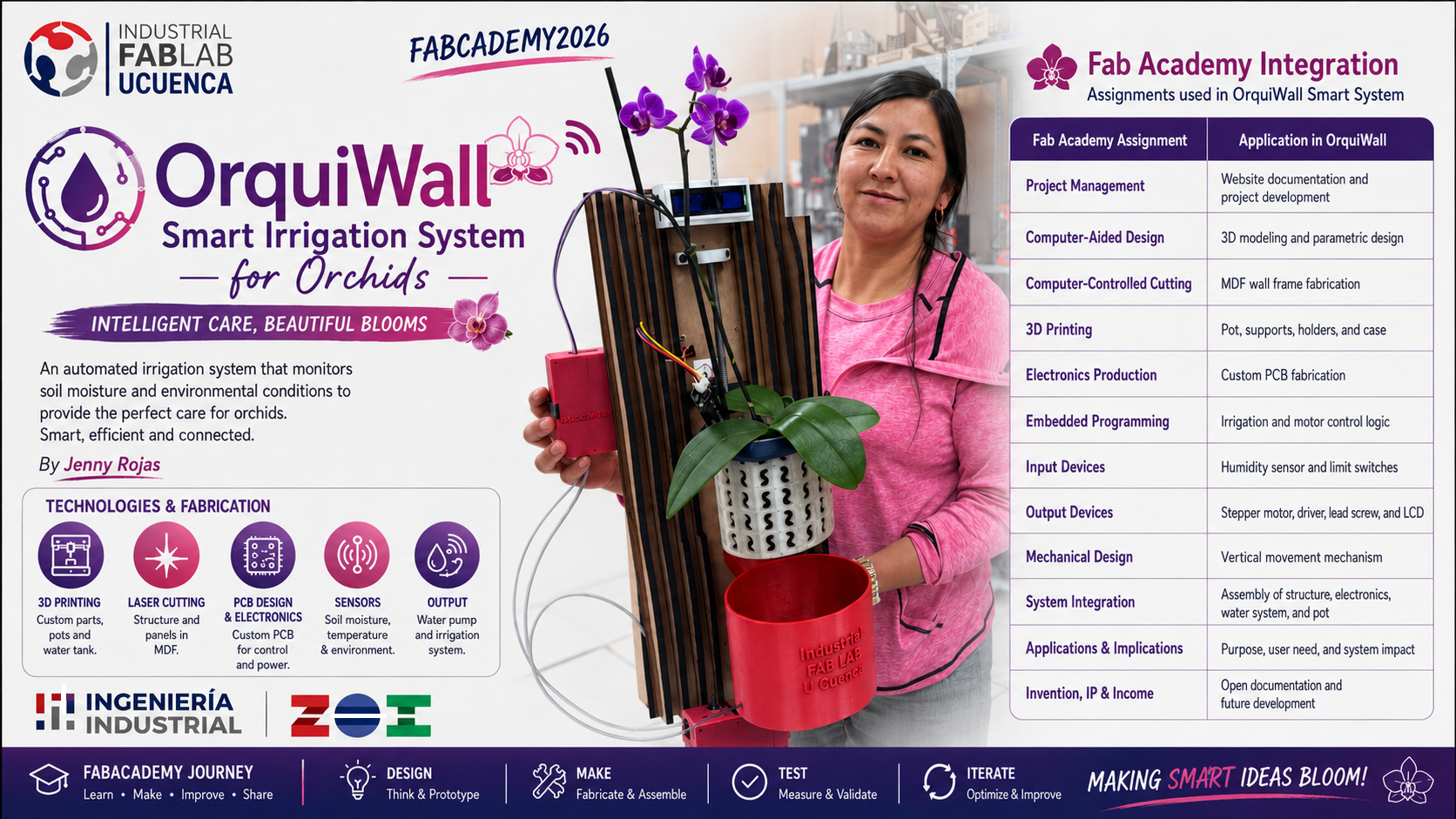
- ✅ Summary slide linked as presentation.png.
- ✅ Video clip linked as presentation.mp4.
Assignment Objective
In this week I documented the application, implications, planning, sourcing, progress tracking, and evaluation strategy of my final project. As a Fab Academy student, I used this assignment to clarify what my project does, who it is for, what parts I need to make or buy, which fabrication processes I will use, where the materials and components can be purchased, and how I will evaluate the final prototype.
I also reviewed the final project communication requirements, especially the need to prepare a project summary slide and a short video showing the concept, construction, and operation of the project.
Project Scope and Fab Academy Integration
The scope of my final project is to develop an independently operable smart orchid irrigation system that integrates the main skills learned during Fab Academy. The project is not only a decorative object or a plant support; it is a complete system that combines design, fabrication, electronics, programming, mechanical movement, and final packaging.
OrquiWall Smart System was planned as a final project masterpiece because it brings together different units covered during the program. The objective is to demonstrate individual mastery by designing and making the main structural, mechanical, and electronic integration parts instead of only assembling commercial modules.
| Fab Academy Requirement | How It Is Integrated in My Project | Evidence |
|---|---|---|
| 2D Design | I designed the wall frame layout and prepared the cutting files for the MDF sliced structure. | DXF file and MDF frame assembly. |
| 3D Design | I modeled the orchid pot, water reservoir, cable case, motor supports, and bearing holders. | Fusion 360 files, F3D files, and STL files. |
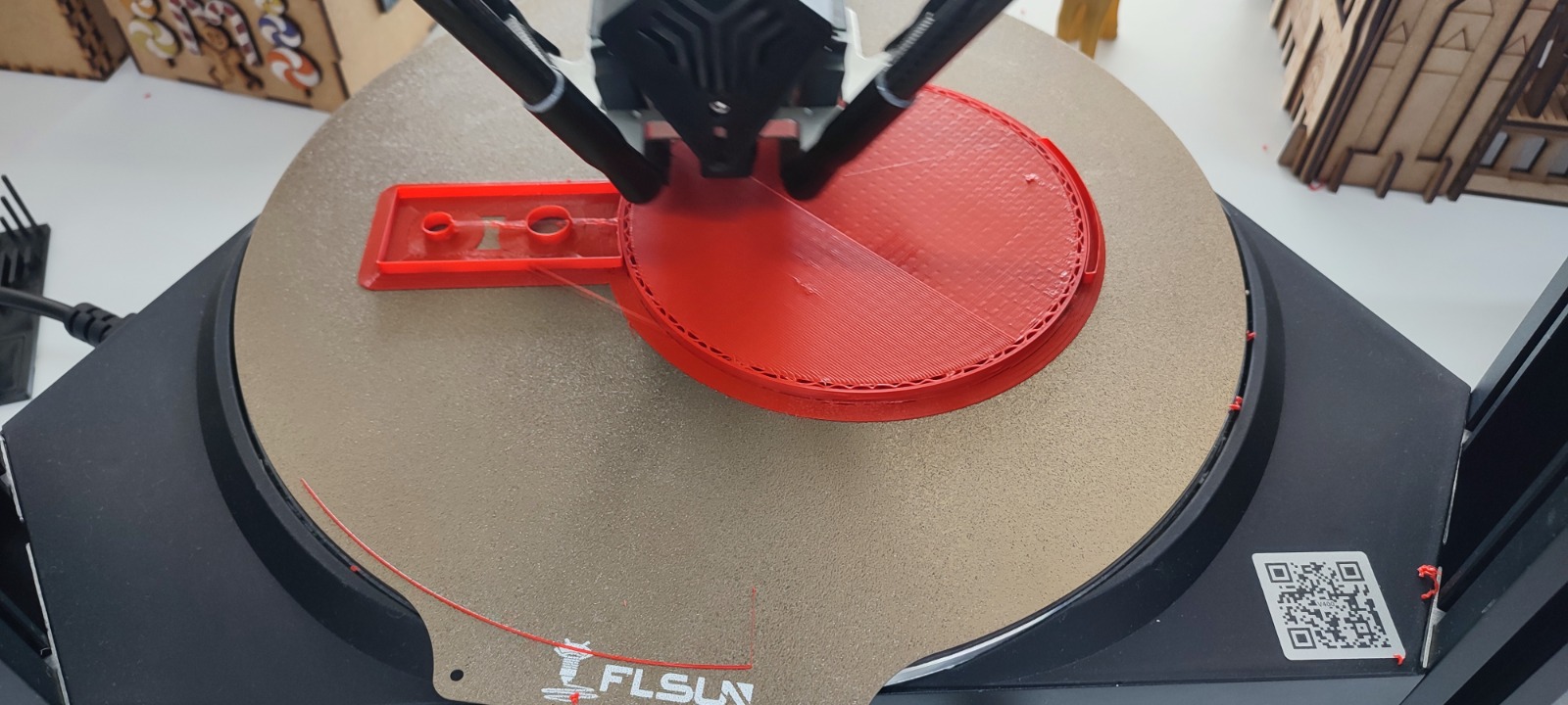
| Additive Fabrication | I fabricated the custom parts using FDM 3D printing in PLA. | Printed reservoir, pot, supports, and wiring case. |
| Subtractive Fabrication | I used laser cutting for the MDF frame and fiber laser fabrication for the PCB. | Laser-cut structure and fabricated PCB. |
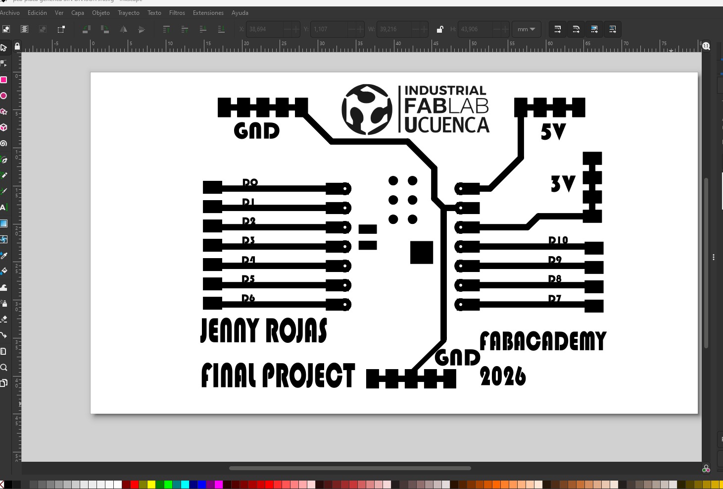
| Electronics Design | I designed a custom PCB to organize the ESP32 XIAO C3, A4988 driver, sensors, display, and limit switches. | KiCad schematic and PCB layout. |
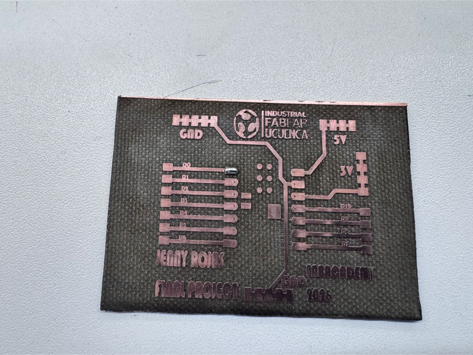
| Electronics Production | I fabricated, soldered, and tested the custom PCB. | Engraved board, soldered components, and continuity testing. |
| Embedded Microcontroller Interfacing and Programming | I programmed the ESP32 XIAO C3 to read sensors, control the display, move the stepper motor, and respond to the limit switches. | Arduino IDE code and functional tests. |
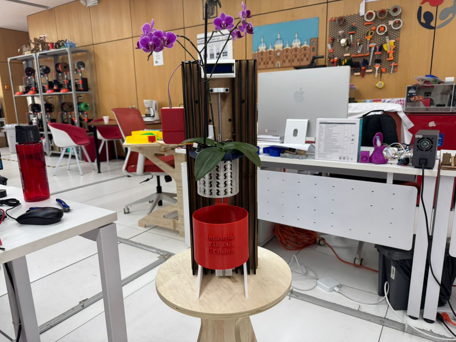
| System Integration and Packaging | I integrated the structure, electronics, wiring, mechanism, reservoir, orchid pot, and user interface into one final prototype. | Final assembled prototype, slide, video, and documentation. |
Make rather than buy: The commercial components used in the project are mainly electronic and mechanical standard parts such as the ESP32 XIAO C3, A4988 driver, sensors, motor, lead screw, and display. However, the project-specific parts were designed and made by me, including the MDF wall frame, 3D printed reservoir, orchid pot, wiring case, motor supports, bearing holders, custom PCB, programming, and final integration.
What Will It Do?
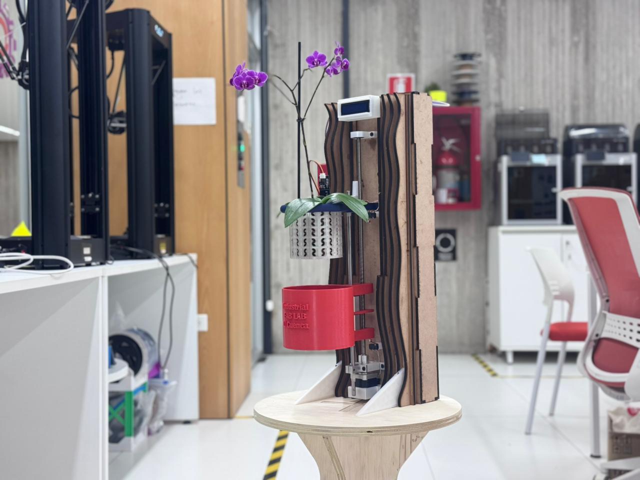
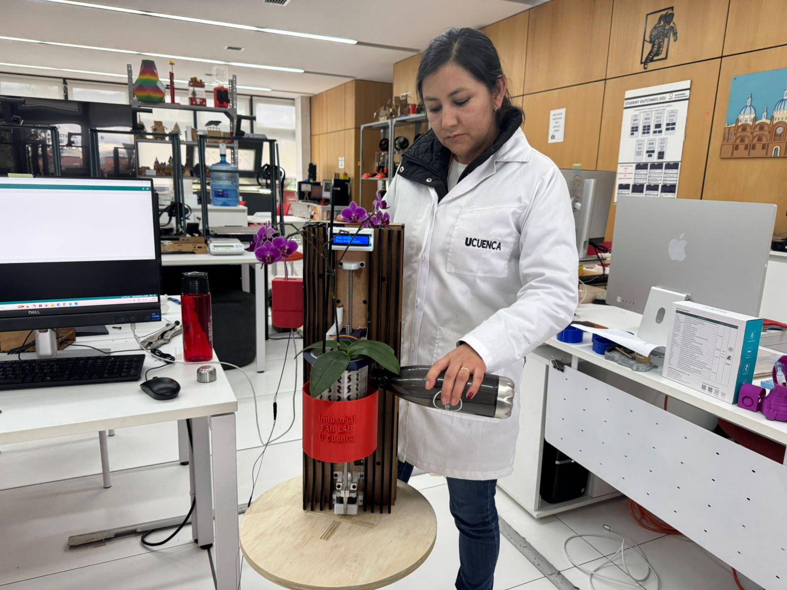
My final project, OrquiWall Smart System, will work as a smart wall module for orchid care. I designed it to combine a digitally fabricated MDF frame, a 3D printed orchid pot, a water reservoir, a custom PCB, sensors, an LCD/OLED interface, and a motorized mechanism. The system supports a real orchid, monitors humidity conditions, displays information, and validates an automated irrigation concept inside a biophilic wall object.
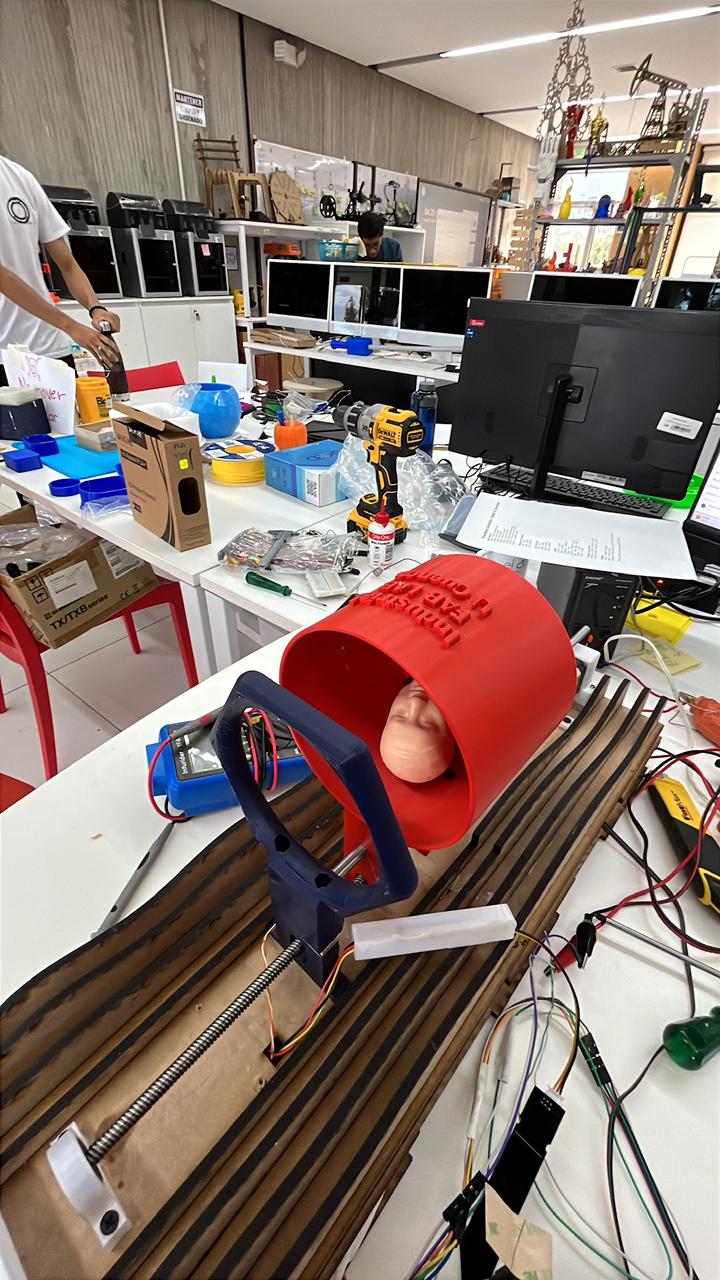
The main idea is to automate orchid watering by immersion. Instead of using a conventional drip system, the project uses a motorized lifting mechanism to move the water reservoir until the orchid pot reaches the immersion level. After the watering time, the reservoir returns to its lower position. This approach is useful for orchids because their substrate usually requires controlled wetting and drainage instead of continuous water saturation.
Who Has Done What Beforehand?
Before developing my final project, I reviewed previous projects related to ESP32 smart irrigation, automatic orchid watering, 3D printed orchid watering systems, and immersion-based orchid care. These projects are useful references, but none of them is exactly the same as my proposal. They helped me identify existing solutions and define the specific contribution of my project.
The references show different approaches: some projects focus on remote monitoring and automation using ESP32, while others focus on orchid watering through 3D printed containers or soaking systems. My project combines these ideas into one integrated Fab Academy prototype: a wall-mounted orchid care system with digital fabrication, custom electronics, sensors, display, and a motorized immersion mechanism.
| Previous Project / Reference | What It Does | Link | Similarity with My Project | Difference in OrquiWall |
|---|---|---|---|---|
| ESP32 IoT Smart Irrigation System: Remote Monitoring and Automation | This type of project uses an ESP32 microcontroller, moisture sensors, wireless communication, and an online dashboard to monitor plant conditions and automate irrigation remotely. | ESP32 Smart Irrigation reference | It is similar because it uses ESP32-based control, sensors, and remote monitoring for plant irrigation. | My project is not a conventional irrigation system with a pump or valve. OrquiWall applies the irrigation decision to an orchid-specific immersion process using a mechanical lifting system. |
| MissOrchidGirl - 3DPing Automatic Watering System | This reference presents an automatic watering system for orchids developed by 3DPing. It is focused on orchid care and shows a product-oriented solution for watering orchids automatically. | MissOrchidGirl reference | It is similar because it is specifically focused on orchids and automatic watering. | My project is developed as a Fab Academy prototype. It includes my own fabricated wall frame, 3D printed parts, custom PCB, sensors, display, and mechanical movement system. |
| My 3D printed automatic orchid watering systems - r/orchids | This community project shows automatic orchid watering systems designed and 3D printed by the author. The system uses the idea of soaking orchids in water for a controlled period of time. | Reddit orchid watering reference | It is very close to my project because it also uses the concept of temporary immersion or soaking. | My version does not only present a 3D printed watering device. It integrates the immersion concept into a vertical biophilic wall object with electronics, an ESP32 XIAO C3, end stops, LCD feedback, and a motorized axis. |
| Automatic Orchid Watering System - 17 cm by Lev / 3DPing - Printables | This is a downloadable 3D printable orchid watering system. It includes 3D printed parts designed to support automatic watering for orchids. | Printables model | It is similar because it uses digital fabrication and is designed specifically for orchid watering. | OrquiWall is not only a printable pot or reservoir. It is a complete integrated system with MDF laser cutting, 3D printing, electronics design, embedded programming, sensors, display, and mechanical movement. |
Project differentiation: These references show that automatic orchid watering and ESP32-based smart irrigation already exist, but my project is different because it combines orchid immersion watering with a custom digitally fabricated wall structure, a motorized lifting mechanism, a custom PCB, sensors, limit switches, and an interface display.
Fab Academy Global Similar Projects
I also searched the Fab Academy global documentation to identify projects related to smart irrigation, plant care, agriculture, and digitally fabricated plant systems. I did not find an identical project that combines orchid immersion irrigation, a wall-mounted structure, a motorized reservoir, a custom PCB, sensors, display, and packaging in the same way as OrquiWall Smart System. However, I found related projects that helped me compare my idea and clarify the difference of my final project.
| Fab Academy / Global Reference | What It Does | Similarity with OrquiWall | Difference with OrquiWall | Link |
|---|---|---|---|---|
| Smart Irrigation System for Potted Plants - Fab Academy 2024 | This project proposes a smart irrigation system for potted plants using soil moisture monitoring and automatic watering. | It is similar because it uses sensors and automatic irrigation for plant care. | OrquiWall is focused on orchids and uses an immersion irrigation mechanism with a motorized lifting system instead of a conventional pump-based watering system. | Open Fab Academy Smart Irrigation Project |
| Forest Fairy - Fab Academy 2026 | This project is a conversational potted-plant robot that monitors a live plant, moves, and connects over Wi-Fi. | It is similar because it combines plant care, sensing, electronics, programming, and system integration. | OrquiWall does not move as a robot. It is a wall-mounted orchid care module with a motorized reservoir movement for immersion irrigation. | Open Forest Fairy Project |
| Fab Academy Projects around Agriculture - AgriAcademy | This page collects previous Fab Academy projects related to agriculture, irrigation, monitoring, and plant systems. | It is useful because it shows that agriculture and plant care have been explored before in Fab Academy. | OrquiWall contributes a specific orchid immersion irrigation approach with digital fabrication, electronics, mechanical movement, and packaging. | Open AgriAcademy Agriculture Projects |
Conclusion from Fab Academy global search: I found related projects about smart irrigation, plant monitoring, agriculture, and potted plant systems. However, OrquiWall Smart System is different because it combines orchid-specific immersion irrigation, a digitally fabricated wall structure, a custom PCB, a motorized lifting mechanism, sensors, display, limit switches, and final packaging into one integrated prototype.
What Sources Will I Use?
For the development of OrquiWall Smart System, I used different types of sources: previous orchid watering projects, ESP32-based irrigation references, component datasheets, Fab Academy documentation, purchase links, supplier pages, and my own weekly assignments. These sources helped me make technical decisions for the mechanical system, electronics, programming, sourcing, and final integration.
| Source Type | Source / Reference | How I Used It |
|---|---|---|
| Previous projects | Automatic orchid watering systems and ESP32 irrigation systems | To compare existing solutions and define the difference of my project. |
| Fab Academy Global projects | Smart irrigation and plant-care projects documented by other Fab Academy students | To compare the project scope and show that OrquiWall has a different integration approach. |
| Component documentation | ESP32 XIAO C3, A4988 driver, LCD/OLED, sensors, and limit switches | To define wiring, voltage levels, pin configuration, and programming logic. |
| Purchase and supplier sources | Centro Madera, Plexylab, Orellana Electrónica, Tecmikro, Supermaxi, Mouser, and Amazon | To validate the BOM values with real purchase links, distributors, country of origin or supply, and real prices. |
| Fab Academy assignments | My previous weeks: CAD, 3D printing, electronics design, production, input, output, networking, and interface programming | To reuse and integrate the skills developed during the Fab Academy cycle. |
| Fabrication sources | Fusion 360, KiCad, Arduino IDE, slicer software, laser cutting workflow, and fiber laser PCB workflow | To design, fabricate, program, and assemble the final prototype. |
What Will Be Designed?
For this project I designed the parts that make the system specific to my final idea. I did not want to use only commercial modules; I wanted the frame, pot, reservoir, electronics case, motor supports, and PCB to be part of the same design language and fabrication workflow.
| Designed Element | Software / Method | Role |
|---|---|---|
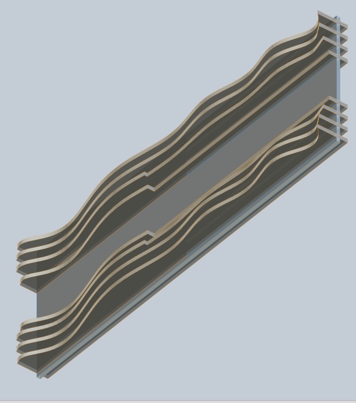
| Organic wall frame | Fusion 360 and Slicer for Fusion 360 | Main structural and aesthetic support. |
| Water reservoir and orchid pot elements | Fusion 360 and Ultimaker Cura | Biological and irrigation interface. |
| Wiring case | Fusion 360 and FDM printing | Protects and organizes system wiring. |
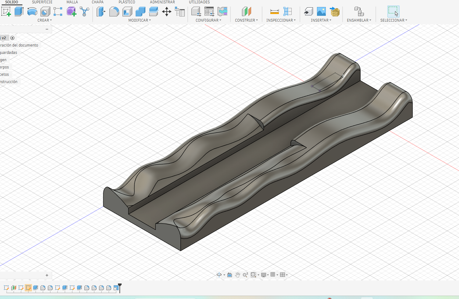
| Motor supports and bearing holders | Fusion 360 and FDM printing | Supports lead screw, motor, and moving axis. |
| Custom PCB | KiCad and vector trace preparation | Connects ESP32 XIAO C3, A4988, sensors, display, and switches. |
What Parts and Systems Will Be Made?
The project is divided into several physical and electronic systems. Some components are purchased, but the main integration parts are designed, fabricated, assembled, and tested by me. This allows the final project to show individual mastery of digital fabrication, electronics, programming, and system integration.
| Part / System | Will Be Made or Integrated | Fabrication / Development Method |
|---|---|---|
| Wall frame | Made by me | 2D design, slicing, and laser cutting in MDF. |
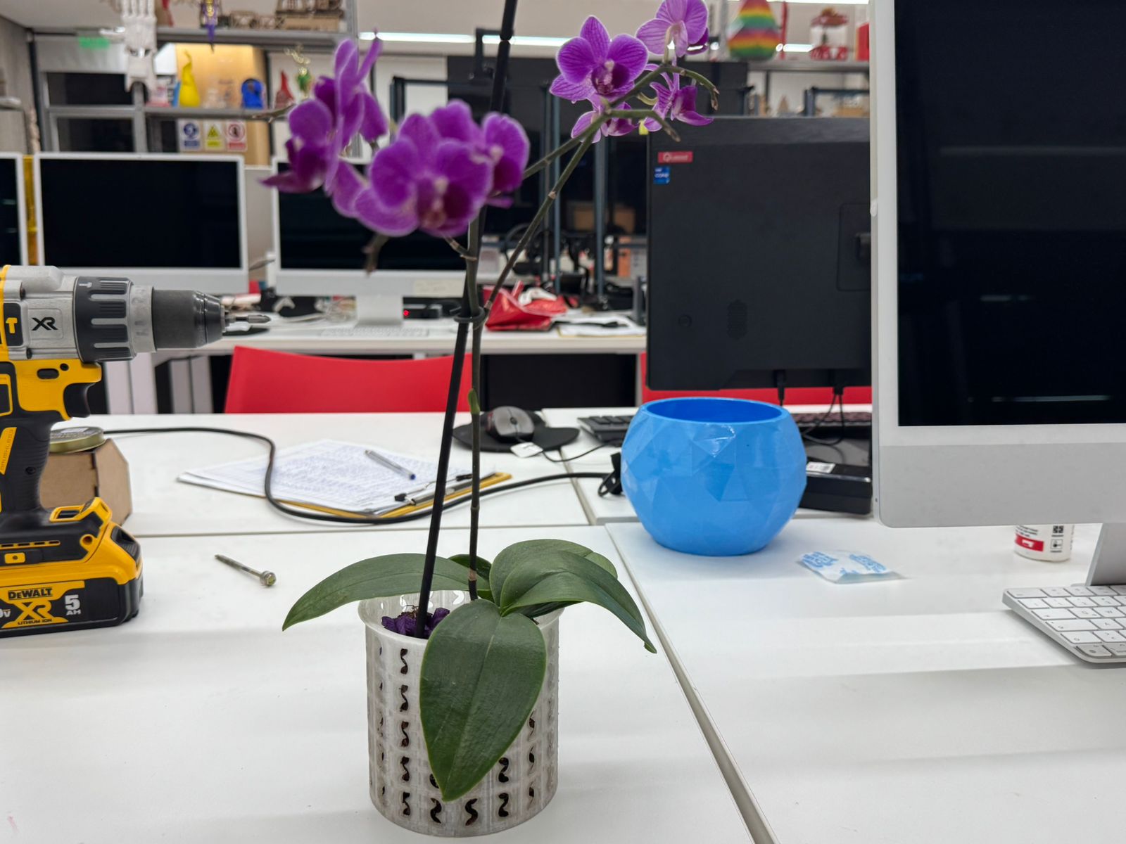
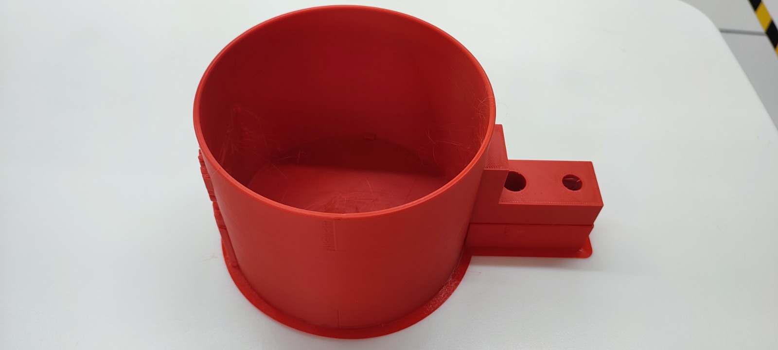
| Orchid pot and water reservoir | Made by me | 3D design and FDM 3D printing. |
| Motor supports and bearing holders | Made by me | 3D design and FDM 3D printing. |
| Wiring case | Made by me | 3D design and FDM 3D printing. |
| Custom PCB | Made by me | KiCad design, PCB fabrication, soldering, and testing. |
| Embedded control system | Programmed and integrated by me | Arduino IDE programming for ESP32 XIAO C3. |
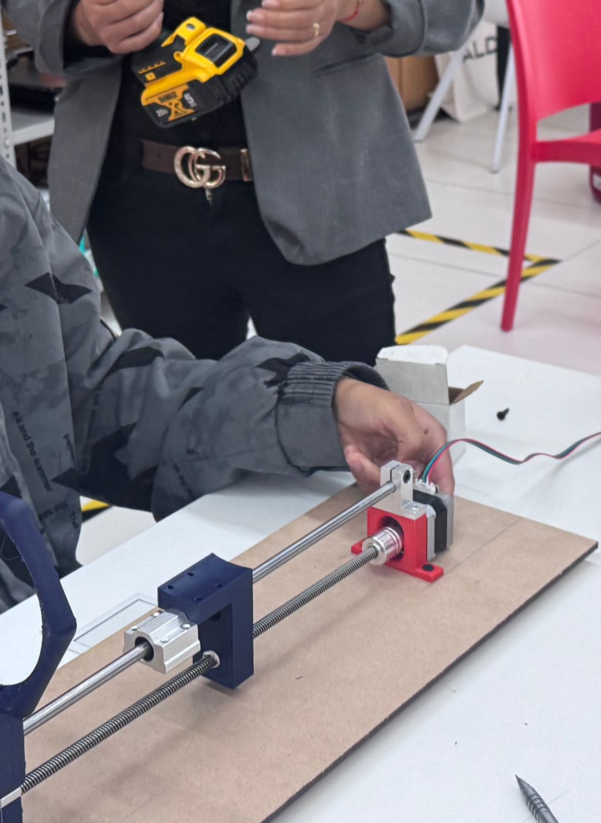
| Automatic immersion mechanism | Integrated by me | Stepper motor, A4988 driver, lead screw, guide rods, and limit switches. |
| User interface | Integrated by me | LCD/OLED display showing humidity, movement, and system status. |
| Final integrated prototype | Assembled and tested by me | Integration of structure, electronics, mechanism, reservoir, plant, and interface. |
What Materials and Components Will Be Used?
I selected the materials according to the fabrication process and the role of each component. MDF is used for the cut frame, PLA for the printed parts, and electronic/mechanical components for sensing, display, and movement. The project uses both fabricated and purchased parts because the goal is system integration.
| Category | Materials / Components | Use |
|---|---|---|
| Structure | MDF 5.5 mm | Laser-cut sliced frame and press-fit support. |
| 3D printed parts | PLA filament | Pot, reservoir, cable case, motor supports, bearing holders, and internal holders. |
| Control electronics | Custom PCB, ESP32 XIAO C3, A4988 stepper motor driver | Central control, motor driving, and circuit organization. |
| Input devices | Capacitive humidity sensor, water level/contact sensor, 2 limit switches | Moisture monitoring, water detection, and motion end-stop references. |
| Output devices | LCD/OLED display, stepper motor, status LED | User feedback, mechanical movement, and visual system indication. |
| Electronic support parts | 220 Ω resistor, 10 kΩ resistors, 100 µF capacitor, pin headers, screw terminals, jumper wires, copper board | Signal conditioning, LED protection, A4988 power stabilization, wiring, and PCB assembly. |
| Mechanical system | Stepper motor 12-15 V, 40 cm lead screw, bearing, guide rods, screws, nuts, washers | Movement and positioning mechanism. |
| Power system | 12 V power supply, USB cable, power terminals, switch | Power supply for microcontroller testing and motor movement. |
| Plant system | Orchid, substrate, reservoir water | Biological validation and irrigation test. |

Where Will They Come From?
The project combines materials and components available in the Fab Lab with commercial electronic and mechanical parts. Whenever possible, I made the structural, mechanical, and electronic integration parts myself instead of buying finished assemblies. I also identified the distributor, country of origin or supply reference, and purchase link for each material and component to strengthen the sourcing and planning section of the project.
| Item / Material | Distributor / Supplier Type | Country of Origin / Supply | Use in the Project |
|---|---|---|---|
| MDF sheet | Centro Madera Ecuador / local supplier | Ecuador | Laser-cut wall frame. |
| PLA filament | Plexylab Ecuador / local supplier | Ecuador / imported material | 3D printed pot, reservoir, case, and supports. |
| Custom PCB | Plexylab FR4 board and Fab Lab fabrication | Ecuador supply / fabricated in Ecuador | Main control board for the final project. |
| ESP32 XIAO C3 | Mouser Ecuador | China / international distributor | Microcontroller for control, sensing, and output management. |
| A4988 stepper motor driver | Plexylab Ecuador | Ecuador supply / imported component | Driver used to control the stepper motor. |
| Electronic components | Plexylab Ecuador, Tecmikro Ecuador, Orellana Electrónica, and Amazon | Ecuador supply / imported electronic components / international supplier | Input, output, signal conditioning, PCB assembly, and system wiring. |
| Mechanical components | Tecmikro Ecuador and Amazon | Ecuador supply / international supplier | Motorized lifting mechanism. |
| Orchid and substrate | Supermaxi / local plant supplier | Ecuador | Biological validation of the irrigation concept. |
Real Purchase Links and Real Prices
To make the BOM values realistic, I added direct purchase links for the main materials and components. The prices shown in this table are real supplier prices checked during the documentation process. Some prices may change over time depending on stock, supplier updates, shipping, taxes, import conditions, or local availability.
Supplier selection criteria: For this BOM, I prioritized local Ecuadorian suppliers when available. When a local supplier was not clearly available, I used an international supplier such as Amazon or an official distributor such as Mouser as the purchase reference. Each item has only one distributor to make the BOM clearer and easier to review.
| Material / Component | Distributor | Purchase Link | Real Price | Country / Supply | Used For |
|---|---|---|---|---|---|
| MDF sheet 5.5 mm | Centro Madera Ecuador | Buy MDF 5.5 mm | $24.00 | Ecuador | Laser-cut wall frame. |
| PLA filament 1 kg | Plexylab Ecuador | Buy PLA filament | $20.00 | Ecuador / imported material | 3D printed parts. |
| FR4 PCB copper board | Plexylab Ecuador | Buy FR4 board | $2.25 | Ecuador supply / imported PCB material | Custom PCB fabrication. |
| Seeed Studio XIAO ESP32C3 | Mouser Ecuador | Buy XIAO ESP32C3 | $4.99 | China / international distributor | Main microcontroller. |
| A4988 stepper motor driver | Plexylab Ecuador | Buy A4988 driver | $1.90 | Ecuador supply / imported electronic component | Stepper motor control. |
| NEMA 17 stepper motor | Tecmikro Ecuador | Buy NEMA 17 stepper motor | $16.92 | Ecuador supply / imported component | Motorized lifting mechanism. |
| Lead screw T8 400 mm | Amazon | Buy T8 lead screw 400 mm | $15.99 | United States / international supplier | Linear movement system. |
| KP08 bearing support | Amazon | Buy KP08 bearing support | $5.00 | United States / international supplier | Lead screw support. |
| 8 mm linear guide rods | Amazon | Buy 8 mm linear guide rods | $4.99 | United States / international supplier | Movement alignment. |
| Capacitive soil moisture sensor | Plexylab Ecuador | Buy capacitive humidity sensor | $2.70 | Ecuador supply / imported electronic component | Substrate humidity reading. |
| Water level sensor | Plexylab Ecuador | Buy water level sensor | $1.25 | Ecuador supply / imported electronic component | Water presence detection. |
| Limit switches | Tecmikro Ecuador | Buy limit switches | $0.92 each | Ecuador supply / imported component | Upper and lower end-stop references. |
| LCD 16x2 I2C display | Orellana Electrónica | Buy LCD 16x2 I2C | $4.20 | Ecuador supply / imported component | User interface. |
| LED 5 mm | Amazon | Buy LED 5 mm | $0.20 | United States / international supplier | Status indication. |
| Resistors 220 Ω and 10 kΩ | Amazon | Buy resistor kit | $0.03 each | United States / international supplier | Signal conditioning and LED protection. |
| 100 µF capacitor | Plexylab Ecuador | Buy electrolytic capacitor | $0.09 | Ecuador supply / imported component | A4988 power stabilization. |
| Pin headers | Plexylab Ecuador | Buy pin headers | $0.55 | Ecuador supply / imported component | PCB connections. |
| Screw terminals | Plexylab Ecuador | Buy screw terminals | $0.18 each | Ecuador supply / imported component | Secure wire connections. |
| Dupont jumper wires | Plexylab Ecuador | Buy jumper wires | $1.40 | Ecuador supply / imported component | System wiring. |
| 12 V 2 A power supply | Plexylab Ecuador | Buy 12 V power supply | $4.40 | Ecuador supply / imported component | Motor driver power. |
| Power switch | Tecmikro Ecuador | Buy power switch | $0.52 | Ecuador supply / imported component | Manual system control. |
| Screws, nuts, and washers kit | Amazon | Buy screws, nuts and washers kit | $12.50 | United States / international supplier | Mechanical assembly. |
| Orchid and orchid substrate | Supermaxi | Buy mini orchid | $13.40 | Ecuador | Biological validation. |
Project Plan and Schedule
I developed the project plan as a sequence of design, fabrication, electronics, programming, integration, sourcing validation, and communication tasks. This schedule helped me organize the work and connect each task with the final evaluation requirements.
| Stage | Task | Expected Result | Status |
|---|---|---|---|
| 1. Concept definition | Define the final project idea, application, user context, and orchid irrigation method. | Clear project scope and application. | Completed |
| 2. Reference review | Review previous projects related to ESP32 irrigation, orchid watering, Fab Academy global plant projects, and 3D printed watering systems. | Comparison table and project differentiation. | Completed |
| 3. 2D and 3D design | Design the MDF wall frame, pot, reservoir, motor supports, bearing holders, and wiring case. | CAD files, STL files, and DXF files. | Completed |
| 4. Additive fabrication | 3D print the pot, reservoir, supports, and electronic case. | Functional PLA parts. | Completed |
| 5. Subtractive fabrication | Laser cut the MDF structure and fabricate the PCB using the fiber laser process. | MDF frame and custom PCB. | Completed |
| 6. Electronics design and production | Design the schematic, prepare the PCB, solder components, and test continuity. | Functional custom control board. | Completed |
| 7. Embedded programming | Program the ESP32 XIAO C3 to read sensors, show information, and control the motorized mechanism. | Working embedded control code. | Completed |
| 8. Mechanical testing | Test the motor, A4988 driver, lead screw, bearing, guide rods, and limit switches. | Validated movement concept. | Prototype tested |
| 9. System integration | Assemble the structure, electronics, reservoir, plant support, mechanism, wiring, and interface. | Integrated prototype. | Completed |
| 10. Sourcing and BOM validation | Add country of origin, distributor, purchase link, and real price for every material and component. | Updated sourcing table and BOM. | Completed |
| 11. Final communication | Prepare the summary slide, video, project files, BOM, and final documentation. | presentation.png, presentation.mp4, project files, and updated documentation. | Completed |
Detailed Bill of Materials — BOM
The following BOM includes all the main materials, components, and support elements used in the project. Each item includes one distributor, one purchase link, country of origin or supply, and one real price obtained from supplier pages or online purchase references.
Supplier selection criteria: For this BOM, I prioritized local Ecuadorian suppliers when available. When a local supplier was not clearly available, I used an international supplier such as Amazon or an official distributor such as Mouser as the purchase reference. Each item has only one distributor to make the BOM clearer and easier to review.
| # | Component / Material | Qty. | Type | Function in the System | Make / Buy | Distributor | Country of Origin / Supply | Purchase Link | Real Unit Price | Real Total |
|---|---|---|---|---|---|---|---|---|---|---|
| 1 | MDF sheet 5.5 mm | 1 | Structure | Laser-cut sliced wall frame. | Buy + fabricate | Centro Madera Ecuador | Ecuador | Buy MDF 5.5 mm | $24.00 | $24.00 |
| 2 | PLA filament 1 kg | 1 roll / partial use | 3D printing | Pot, reservoir, case, motor supports, and bearing holders. | Buy + fabricate | Plexylab Ecuador | Ecuador / imported material | Buy PLA filament | $20.00 | $20.00 |
| 3 | FR4 PCB copper board 100 x 150 mm | 1 | Electronics production | Base material for fabricating the custom PCB. | Buy + fabricate | Plexylab Ecuador | Ecuador supply / imported PCB material | Buy FR4 PCB board | $2.25 | $2.25 |
| 4 | Seeed Studio XIAO ESP32C3 | 1 | Microcontroller | Reads sensors, controls outputs, and manages the irrigation logic. | Buy | Mouser Ecuador | China / international distributor | Buy XIAO ESP32C3 | $4.99 | $4.99 |
| 5 | A4988 stepper motor driver | 1 | Motor driver | Controls the stepper motor movement. | Buy | Plexylab Ecuador | Ecuador supply / imported electronic component | Buy A4988 driver | $1.90 | $1.90 |
| 6 | NEMA 17 stepper motor | 1 | Actuator | Moves the lifting mechanism for immersion watering. | Buy | Tecmikro Ecuador | Ecuador supply / imported electronic component | Buy NEMA 17 stepper motor | $16.92 | $16.92 |
| 7 | Lead screw T8 400 mm with nut | 1 | Mechanical transmission | Converts motor rotation into vertical linear movement. | Buy | Amazon | United States / international supplier | Buy T8 lead screw 400 mm | $15.99 | $15.99 |
| 8 | KP08 bearing support 8 mm | 1 | Mechanical support | Stabilizes the lead screw rotation. | Buy | Amazon | United States / international supplier | Buy KP08 bearing support | $5.00 | $5.00 |
| 9 | Linear guide / 8 mm rod support set | 1 set | Mechanical guide | Helps the moving platform stay aligned. | Buy | Amazon | United States / international supplier | Buy 8 mm linear guide rods | $4.99 | $4.99 |
| 10 | Capacitive soil moisture sensor | 1 | Input sensor | Monitors substrate moisture conditions. | Buy | Plexylab Ecuador | Ecuador supply / imported electronic component | Buy capacitive humidity sensor | $2.70 | $2.70 |
| 11 | Water level sensor | 1 | Input sensor | Detects water presence for irrigation validation. | Buy | Plexylab Ecuador | Ecuador supply / imported electronic component | Buy water level sensor | $1.25 | $1.25 |
| 12 | Limit switches | 2 | Input / safety | Upper and lower end-stop references for the moving mechanism. | Buy | Tecmikro Ecuador | Ecuador supply / imported electronic component | Buy limit switches | $0.92 | $1.84 |
| 13 | LCD 16x2 I2C display | 1 | Output interface | Displays system status, humidity level, and movement messages. | Buy | Orellana Electrónica | Ecuador supply / imported electronic component | Buy LCD 16x2 I2C | $4.20 | $4.20 |
| 14 | Status LED 5 mm | 1 | Output indicator | Visual indication of system state. | Buy | Amazon | United States / international supplier | Buy LED 5 mm | $0.20 | $0.20 |
| 15 | 220 Ω resistor | 1 | Electronic component | Limits current for the LED indicator. | Buy | Amazon | United States / international supplier | Buy 220 Ω resistor | $0.03 | $0.03 |
| 16 | 10 kΩ resistors | 2 | Electronic component | Pull-up or pull-down support for stable digital input readings. | Buy | Amazon | United States / international supplier | Buy 10 kΩ resistors | $0.03 | $0.06 |
| 17 | 100 µF electrolytic capacitor | 1 | Electronic component | Stabilizes the motor driver power input near VMOT and GND. | Buy | Plexylab Ecuador | Ecuador supply / imported electronic component | Buy electrolytic capacitor | $0.09 | $0.09 |
| 18 | Pin headers 1x40 | 1 | PCB assembly | Connects XIAO, driver, sensors, and display to the PCB. | Buy | Plexylab Ecuador | Ecuador supply / imported electronic component | Buy pin headers | $0.55 | $0.55 |
| 19 | Screw terminals KF301 | 10 units | PCB assembly | Provides secure connections for motor power, sensors, and outputs. | Buy | Plexylab Ecuador | Ecuador supply / imported electronic component | Buy screw terminals | $0.18 | $1.80 |
| 20 | Dupont jumper wires 40 units | 1 set | Wiring | Connects electronic modules, sensors, display, and power lines. | Buy | Plexylab Ecuador | Ecuador supply / imported electronic component | Buy jumper wires | $1.40 | $1.40 |
| 21 | 12 V 2 A power supply | 1 | Power | Provides external power for the stepper motor driver. | Buy | Plexylab Ecuador | Ecuador supply / imported electronic component | Buy 12 V power supply | $4.40 | $4.40 |
| 22 | Power switch | 1 | Power / safety | Allows the system to be turned on and off manually. | Buy | Tecmikro Ecuador | Ecuador supply / imported electronic component | Buy power switch | $0.52 | $0.52 |
| 23 | Screws, nuts, and washers kit | 1 kit | Assembly | Used for mechanical fastening and component mounting. | Buy | Amazon | United States / international supplier | Buy screws, nuts and washers kit | $12.50 | $12.50 |
| 24 | Orchid and orchid substrate | 1 plant + 1 substrate bag | Plant system | Biological element used to validate the irrigation concept. | Buy | Supermaxi | Ecuador | Buy mini orchid | $13.40 | $13.40 |
| Real total | $140.98 | |||||||||
Note: The BOM includes only one distributor, one purchase link, and one real price for each material or component. Local Ecuadorian suppliers were prioritized when available. For components that were not clearly available locally, Amazon or official international distributors were used as real purchase references. Prices may change over time depending on stock, shipping, supplier updates, and local availability.
How Much Will It Cost?
For the cost estimate, I used real values from supplier pages, local availability, Fab Lab material use, and commercial purchase links. I also considered that some materials, such as MDF and PLA, are only partially used in the final prototype even if the full sheet or full filament roll is purchased.
| Cost Group | Included Items | Real Cost | Reference / Notes |
|---|---|---|---|
| Structure and fabricated parts | MDF sheet, PLA filament, screws, nuts, and washers. | $56.50 | MDF, PLA, and mechanical assembly kit values were updated using real purchase links. |
| Control electronics | ESP32 XIAO C3, FR4 PCB board, A4988 driver, pin headers, and screw terminals. | $11.49 | Includes real XIAO, PCB board, A4988, headers, and terminals supplier values. |
| Sensors and interface | Humidity sensor, water sensor, limit switches, LCD/OLED, LED, and resistors. | $10.21 | Includes humidity sensor, water level sensor, LCD, switches, and small electronic components. |
| Mechanical movement | Stepper motor, 40 cm lead screw, bearing, and guide rods. | $42.90 | Mechanical parts were priced using local or international purchase links. |
| Power and wiring | 12 V power supply, switch, capacitor, jumper wires, cables, and connectors. | $6.48 | Includes wiring, capacitor, power supply, and switch. |
| Plant system | Orchid and orchid substrate. | $13.40 | Plant and substrate values are included as biological validation materials. |
| Total project cost | All project subsystems | $140.98 | Total cost using real purchase links and real supplier values. |
Note: These values may vary depending on availability, shipping, supplier updates, and whether some materials are already available in the Fab Lab.
What Processes Will Be Used?
As a Fab Academy student, I used different digital fabrication processes to make each layer of the project. I used CAD to design the objects, laser cutting for the MDF frame, 3D printing for the pot and supports, KiCad for PCB design, fiber laser for PCB fabrication, and embedded programming for system control.
| Fab Academy Area | Process Used in My Final Project | Evidence / Result |
|---|---|---|
| 2D Design | DXF layout for the MDF sliced wall frame. | Laser cutting files and frame assembly. |
| 3D Design | Fusion 360 models for the pot, reservoir, case, and motor supports. | F3D and STL files. |
| Additive Fabrication | FDM 3D printing in PLA. | Printed reservoir, pot, and mechanical supports. |
| Subtractive Fabrication | Laser cutting MDF and fiber laser PCB fabrication. | Frame parts and fabricated PCB. |
| Electronics Design | Custom PCB designed in KiCad. | PCB project files and schematic. |
| Electronics Production | PCB fabrication, soldering, and continuity testing. | Functional board with connected modules. |
| Embedded Programming | Arduino IDE code for ESP32 XIAO C3. | Motor, sensors, LCD/OLED, and end-stop control. |
| System Integration | Assembly of frame, plant, reservoir, electronics, mechanism, and interface. | Final integrated prototype. |
What Questions Need to Be Answered?
Can my MDF sliced frame support the reservoir, orchid pot, and electronics?
I needed to verify that the frame was not only decorative. In my project, the sliced MDF structure has to support the pot, the reservoir, the LCD/OLED, the cable routing, and part of the mechanical system. I evaluated this by assembling the frame and placing the real components on it.
Can my motor, lead screw, and supports move reliably without blocking the structure?
I tested the motorized mechanism separately before integrating it into the final frame. This helped me understand if the lead screw, bearing, guide rods, and printed supports were aligned enough to allow movement without excessive friction.
Can my PCB control the motor and read the sensor signals safely?
I designed and fabricated a custom PCB because I wanted the electronics to be part of the final system, not only a breadboard prototype. I checked the board through soldering, continuity testing, and connection tests with the ESP32 XIAO C3, A4988 driver, LCD/OLED, humidity sensor, water sensor, and limit switches.
Can I route the wiring without interfering with moving parts or the reservoir?
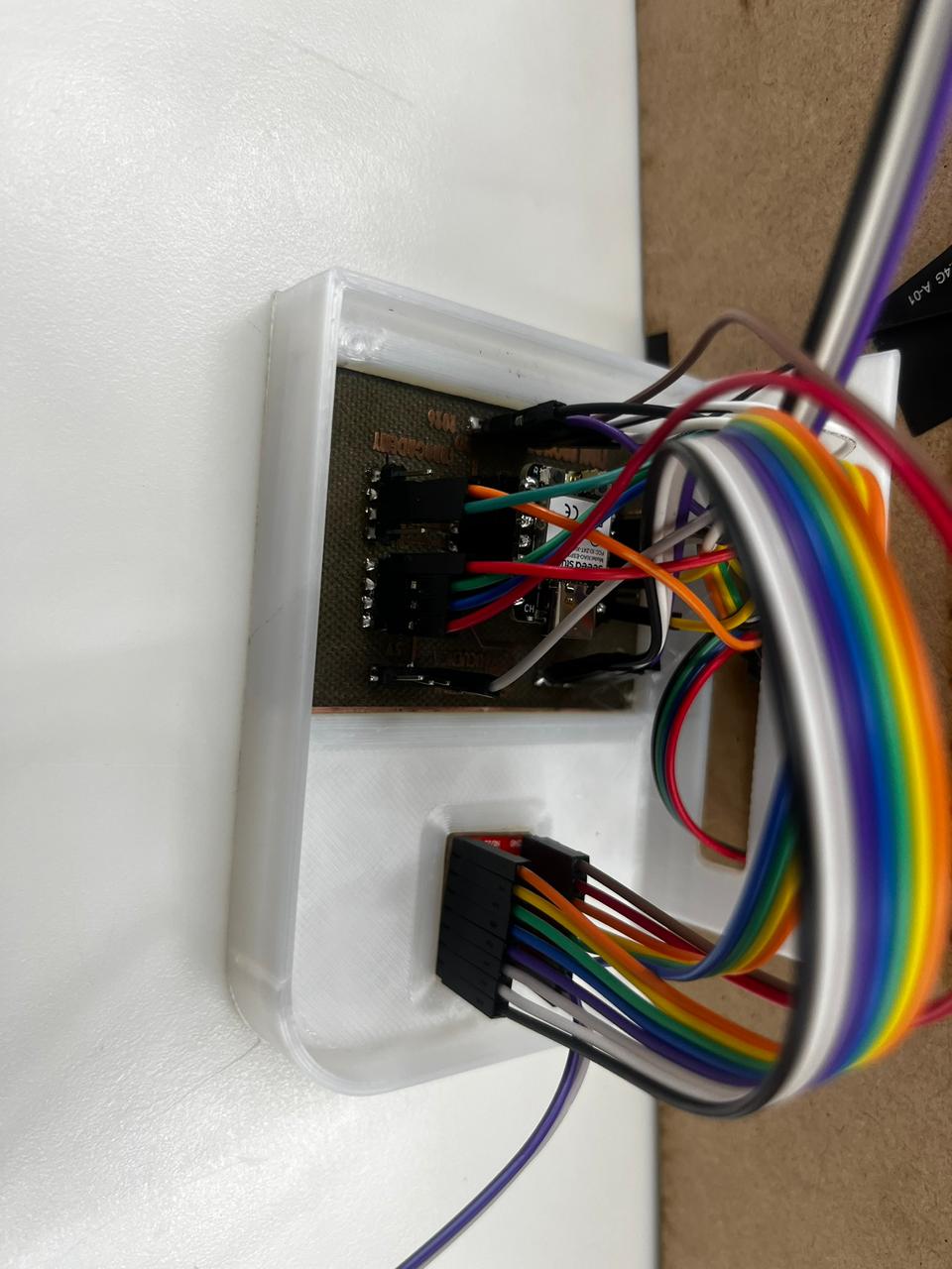
I had to organize the wiring through openings in the MDF frame and inside a printed case. This was important because loose cables could touch the lead screw or make the final prototype difficult to maintain.
Does my final object communicate a smart biophilic product?
I wanted the final result to look like an integrated orchid care object, not only a technical test. For that reason, I used the organic sliced frame, visible orchid, red reservoir, display interface, and final presentation photos to evaluate the design language.
How Will It Be Evaluated?
I evaluated the project as a complete system. My success criteria were not only that each part existed, but that the parts could work together: structure, electronics, movement, irrigation, plant presentation, and documentation.
| Evaluation Area | Success Criteria | Status |
|---|---|---|
| Structure | The frame stands vertically and holds the main components. | Documented / tested |
| Electronics | PCB, ESP32, driver, display, sensor, and switches connect correctly. | Documented / tested |
| Mechanism | Motor and lead screw move without excessive friction or misalignment. | Prototype tested |
| Irrigation concept | Reservoir and pot can be tested with water and orchid placement. | Demonstrated |
| Sourcing and cost | The BOM includes one distributor, country of origin, one purchase link, and one real price for every material and component. | Updated |
| Documentation | Design, fabrication, code, BOM, references, slide, video, and files are explained and downloadable. | Updated in this page |
Track the Progress of My Project
I tracked the progress of OrquiWall Smart System as a sequence of milestones, from the first project idea to the final integrated prototype. I used a progress matrix to connect each task with a deliverable, a verification method, the related Fab Academy week, and its final status. This helped me avoid treating the project as separate assignments and instead follow it as one complete system.
The reference structure for this tracking section was the project progress tracking format used in Rodrigo Guaman's Week 18 documentation. I adapted that logic to my project by organizing the work into planning, design, fabrication, electronics, programming, mechanical movement, integration, communication, and final review tasks.
Tracking method: each milestone was considered complete only when it had visible evidence: design files, fabrication photos, test images, working code, assembly validation, linked files, or final presentation material. When a task affected another subsystem, I added the risk or dependency in the table.
Project Progress Matrix
| Stage | Related Fab Academy Work | Main Task | Deliverable / Evidence | Verification Criteria | Status |
|---|---|---|---|---|---|
| 1. Concept definition | Final project planning | Define OrquiWall as a smart orchid irrigation wall module. | Project description, target users, problem statement, and application explanation. | The project explains what it does, who it is for, and why orchid care needs controlled irrigation. | Completed |
| 2. Reference review | Applications and Implications | Compare previous irrigation, orchid care, and Fab Academy plant projects. | Reference tables, source links, and differentiation notes. | The documentation shows how OrquiWall is different from commercial or previous projects. | Completed |
| 3. System architecture | Project development | Divide the project into structure, electronics, sensing, actuation, interface, and plant-care subsystems. | System description, architecture notes, and integration plan. | Each subsystem has a clear role and connects to the final prototype. | Completed |
| 4. CAD and frame design | W02 CAD / W03 Cutting | Design the MDF sliced wall frame and prepare cutting files. | CAD model, DXF file, laser-cut pieces, and frame assembly photos. | The frame supports the pot, reservoir, interface, and mechanical axis. | Completed |
| 5. Printed components | W05 3D Scanning and Printing | Design and print the orchid pot, water reservoir, cable case, motor supports, and bearing holders. | F3D files, STL files, printed PLA parts, and assembly evidence. | The printed parts fit the mechanical and electronic layout without blocking access. | Completed |
| 6. PCB design | W06 Electronics Design | Design the custom PCB for XIAO ESP32C3, A4988, sensors, display, switches, and connections. | KiCad schematic, board layout, trace artwork, and 3D preview. | The board organizes all main electronic signals and power connections. | Completed |
| 7. PCB fabrication | W08 Electronics Production | Fabricate, drill, solder, and test the custom PCB. | Engraved PCB, drilled board, soldered board, and continuity tests. | The traces are separated correctly and the board is safe to connect. | Completed |
| 8. Input validation | W09 Input Devices | Test humidity sensor, water level sensor, and limit switch references. | Sensor wiring, readings, input tests, and threshold notes. | The system can detect substrate humidity, water presence, and movement limits. | Completed |
| 9. Output validation | W10 Output Devices | Test LCD messages, LED indication, and stepper motor control. | Display tests, motor tests, LED behavior, and wiring evidence. | The output devices respond to the programmed logic. | Completed |
| 10. Embedded logic | W04 Embedded Programming / W16 System Integration | Program the ESP32 XIAO C3 to coordinate sensors, display, motor movement, and safety switches. | Arduino code, serial/debug tests, and functional behavior. | The system follows the irrigation sequence without losing sensor or end-stop control. | Completed |
| 11. Mechanical movement | W12 Mechanical Design, Machine Design | Assemble and test the NEMA 17 motor, A4988 driver, lead screw, bearing, and guide rods. | Motor support tests, lead screw alignment, and movement photos. | The vertical movement is aligned and can support the irrigation concept. | Prototype tested |
| 12. System integration | W16 System Integration | Join the frame, electronics, wiring, mechanism, reservoir, pot, orchid, and interface. | Final assembly photos, wiring case, integrated prototype, and irrigation test. | The prototype works as one system and the wiring does not interfere with movement or water. | Completed |
| 13. Sourcing and cost control | W18 Applications and Implications | Document materials, links, quantities, prices, country/supply reference, and Ecuador referential prices. | Shared BOM, supplier links, published prices, and Ecuador referential total. | All main components have quantity, link, price, and project cost subtotal. | Completed |
| 14. Final communication | W20 Final Project Presentation | Prepare the final slide, video, project files, and final project page. | presentation.png, presentation.mp4, downloadable files, and final project documentation. | The final material communicates the problem, process, prototype, and operation. | Completed |
Gantt by Fab Academy Weeks and Final Project Components
The Gantt chart below shows how each component of my final project was developed across the Fab Academy weeks. I used the weeks as checkpoints because every assignment contributed evidence or a technical layer to OrquiWall.
| Component / Work Package | W01 | W02 | W03 | W04 | W05 | W06 | W07 | W08 | W09 | W10 | W11 | W12 | W13 | W14 | W15 | W16 | W17 | W18 | W19 | W20 |
|---|---|---|---|---|---|---|---|---|---|---|---|---|---|---|---|---|---|---|---|---|
| Project definition and documentation | Scope | Review | Plan | IP | Final | |||||||||||||||
| Wall frame and visual structure | CAD | Cut | Scale | Fit | Review | Integrate | Cost | Present | ||||||||||||
| 3D printed pot, reservoir, case, supports | Model | Mount | Review | Integrate | BOM | Present | ||||||||||||||
| Custom PCB and electronics board | Pins | KiCad | PCB | Review | Wire | Cost | Files | |||||||||||||
| Input sensors: moisture, water level, limits | Code | PCB | Inputs | Review | System | BOM | Demo | |||||||||||||
| Outputs: LCD, LED, stepper motor | Logic | PCB | Outputs | Motor | Review | System | BOM | Demo | ||||||||||||
| Embedded programming and control logic | Base | Read | Move | Comms | Review | UI | Final code | Doc | Files | |||||||||||
| Mechanical movement and irrigation test | Parts | Scale | Motor | Mechanism | Review | Irrigate | Risk | Demo | ||||||||||||
| Interface, files, BOM, and final communication | Repo | Review | Interface | Files | Assets | BOM | License | Slide/video |
Checkpoint Tracking
| Checkpoint | Target Output | Completed Evidence | Decision / Next Action |
|---|---|---|---|
| Midterm review | Confirm final project direction and identify missing technical pieces. | Project scope, preliminary design direction, and subsystem plan. | Continue with the smart orchid irrigation concept and focus on system integration. |
| Before electronics production | Have the PCB schematic and wiring logic ready. | KiCad schematic, board layout, and PCB trace artwork. | Fabricate the PCB and verify continuity before connecting components. |
| Before mechanical integration | Validate that the motor, lead screw, and printed supports can move together. | NEMA 17 motor test, A4988 driver wiring, lead screw support, and alignment checks. | Improve cable routing and avoid friction near moving parts. |
| Before final assembly | Confirm that the electronics, structure, reservoir, and pot can fit in one prototype. | Full system layout photos, wiring case, printed parts, and MDF structure. | Mount the components in the final configuration and test irrigation behavior. |
| Before final presentation | Complete the website evidence, BOM, files, slide, and video. | Updated W18, W20, Final Project page, shared BOM, presentation.png, and presentation.mp4. | Review links, file downloads, visuals, and final project narrative. |
Risk and Dependency Tracking
| Risk / Dependency | Possible Effect | Control Action | Result |
|---|---|---|---|
| Sensor threshold variation | Humidity or water readings could trigger incorrect irrigation decisions. | Test readings in dry, wet, and intermediate conditions and document the logic. | Controlled through sensor testing and code thresholds. |
| Motor and lead screw misalignment | The moving system could block, vibrate, or lose stability. | Use printed supports, bearing support, guide rods, and manual alignment checks. | Prototype movement validated. |
| Water near electronics | Risk of short circuits or unsafe wiring. | Separate the PCB in a wiring case and route cables away from the reservoir. | Controlled in final assembly. |
| Frame load and stability | The MDF frame could deform or fail to hold the plant/mechanism. | Use a sliced frame structure and test the final component placement. | Frame supports the visible prototype. |
| Documentation completeness | Final review could miss evidence if files, prices, or process images are not linked. | Update W18, W20, Final Project page, project files, slide, video, and BOM. | Documentation updated and linked. |
Current Status Summary
By the end of this tracking process, the project reached an integrated prototype stage. The MDF structure, printed pot and reservoir, custom PCB, ESP32 controller, sensors, LCD interface, motorized mechanism, wiring, orchid, final files, BOM, slide, video, and final documentation were completed or linked. The remaining work after each checkpoint was not a new subsystem, but refinement: improving presentation clarity, checking links, making the BOM consistent across pages, and making the website easier to review.
Progress conclusion: OrquiWall moved from a project concept to a documented final prototype. The tracking process shows that the project was developed through measurable milestones: concept definition, design, fabrication, electronics production, input/output testing, programming, mechanical validation, final system integration, sourcing validation, and final communication.
Final Project Communication: Slide and Video
As part of the Project Development requirement, I prepared draft versions of the final project summary slide and video clip. These files communicate the concept, development process, fabrication methods, electronics, integration, and expected operation of OrquiWall Smart System.
The summary slide was prepared as presentation.png in 1920 x 1080 format, and the video clip was prepared as presentation.mp4 in HTML5-compatible format. Both files are placed in the root directory of the project website so they can be accessed during the final presentation review.
Project Development note: At this stage, the slide and video can work as drafts or placeholders. They will be improved as the final prototype is completed and the final evidence is available.
I also checked that the final slide and video are linked in the final presentation schedule so they can be reviewed during the final project presentation process.
Project Development Status
This section summarizes the project development progress and helps verify that the main Fab Academy final project requirements are covered before requesting a new review.
| Requirement / Task | Evidence in the Project | Status |
|---|---|---|
| Project scope | The project scope is defined as a smart orchid irrigation wall system integrating design, fabrication, electronics, programming, and packaging. | Completed |
| 2D design | DXF layout for the MDF wall frame. | Completed |
| 3D design | Fusion 360 models for pot, reservoir, case, and supports. | Completed |
| Additive fabrication | PLA 3D printed parts. | Completed |
| Subtractive fabrication | MDF laser cutting and PCB fiber laser fabrication. | Completed |
| Electronics design | KiCad schematic and custom PCB. | Completed |
| Electronics production | Fabricated and soldered PCB. | Completed |
| Embedded programming | Arduino code for ESP32 XIAO C3, sensors, display, motor, and switches. | Completed |
| System integration | Integrated structure, electronics, mechanism, plant, and reservoir. | Completed |
| Project schedule | The project plan and schedule are documented with stages from concept definition to final communication. | Added |
| Progress tracking | The progress of each subsystem is documented, including evidence, risks, and current status. | Added |
| Country of origin | The BOM and sourcing section include country of origin or supply information for the main materials and components. | Added |
| Distributor information | The BOM includes one distributor for every material and component. | Added |
| Real purchase links | One real purchase link was added for every material and component. | Added |
| BOM | Detailed BOM with one distributor, country of origin, one purchase link, and one real price for every item. | Updated |
| Previous projects / references | Links added in “Who Has Done What Beforehand?” and “Fab Academy Global Similar Projects”. | Updated |
| Slide | presentation.png linked in this page. | Linked |
| Video | presentation.mp4 linked in this page. | Linked |
| Final presentation schedule | Checked and documented in the slide and video section. | Checked |
Project Files
The following files are included to support reproducibility. They contain the 2D cutting files, 3D design files, electronics files, final code, and final project presentation files.
Checklist for New Review
- ✅ What will it do?
- ✅ Who has done what beforehand?
- ✅ Similar Fab Academy global projects reviewed and compared.
- ✅ What sources will you use?
- ✅ What will you design?
- ✅ What materials and components will be used?
- ✅ Where will they come from?
- ✅ Where can the materials and components be purchased?
- ✅ One real purchase link added for every material and component.
- ✅ One distributor added for every material and component.
- ✅ Country of origin of materials and components included in sourcing and BOM sections.
- ✅ How much will they cost?
- ✅ Detailed BOM updated with one distributor, one real purchase link, and one real price for every material and component.
- ✅ What parts and systems will be made?
- ✅ What processes will be used?
- ✅ What questions need to be answered?
- ✅ How will it be evaluated?
- ✅ Track the progress of the project documented in the section Track the Progress of My Project.
- ✅ Uploaded summary slide: presentation.png.
- ✅ Uploaded video clip: presentation.mp4.
- ✅ Checked that slide and video are linked in the final presentation schedule.
This page includes the required project progress tracking section, the country of origin or supply information for the main materials and components, distributor information, real purchase links, real prices, similar Fab Academy global projects, and an updated BOM. These sections were added to strengthen the planning, sourcing, cost validation, and project development documentation.