Week 3 – Computer-Controlled Cutting
Fab Academy 2026 · Jenny Rojas · Industrial FabLab UCuenca
1. Checklist
- ✅ Linked to the group assignment page
- ✅ Reflected on my individual page what I learned from the lab safety training
- ✅ Explained how I created my parametric design
- ✅ Documented the editable parameters and dimensional constraints used in Fusion 360
- ✅ Documented how I made my press-fit construction kit
- ✅ Documented how I made something with the vinyl cutter
- ✅ Included the weeding and transfer process for the vinyl sticker
- ✅ Included the original design files, including the vinyl cutting file
- ✅ Included hero shots of my results
2. Group Assignment
For the group assignment, the lab characterized the laser cutter by analyzing key parameters such as focus, power, speed, rate, kerf, joint clearance, and material behavior. This collaborative work allowed us to understand how different configurations affect cutting quality, engraving definition, edge finishing, and dimensional precision.
During the characterization process, different tests were performed to compare how the machine responds to changes in speed and power. These tests were important because they helped us identify the most appropriate settings for cutting MDF accurately while reducing excessive burning, incomplete cuts, and dimensional errors.
The results obtained from this characterization directly supported the individual development of the press-fit construction kit presented on this page. Understanding the kerf value and the behavior of the material allowed me to define better tolerances, improve the fit between parts, and achieve a stable assembly without glue.
Open Group AssignmentLab Safety Training Reflection
During the lab safety training, I learned that computer-controlled cutting machines must be used with careful attention to material compatibility, machine calibration, ventilation, and personal protection. For the laser cutter, it is important to verify that the material is safe to cut, because some materials can release toxic fumes or damage the machine.
I also learned that the laser cutter must never be left unattended while operating, since materials such as MDF can burn if the power, speed, or focus are not correctly adjusted. Before cutting, I checked the machine bed, verified the focus, confirmed the material position, and made sure that the extraction system was working properly.
For the vinyl cutter, I learned that the blade depth and cutting force must be adjusted carefully to cut only the vinyl layer without damaging the backing paper. I also learned to keep my hands away from the moving carriage and to load the material correctly using the pinch rollers.
This safety training helped me understand that digital fabrication is not only about sending a file to a machine. It also requires checking the material, preparing the machine, monitoring the process, and following safe operating procedures.
Designing a Parametric Construction Kit
3. Project Overview
For the construction of a parametric-based kit, Fusion 360 was used as the main design software. The construction model is based on a modular, interlockable link system designed with press-fit joints that follow precise kerf compensation parameters.
The main objective was to create a construction kit that could be assembled without glue or screws. For this reason, the design needed to consider material thickness, kerf compensation, joint tolerance, and structural stability.
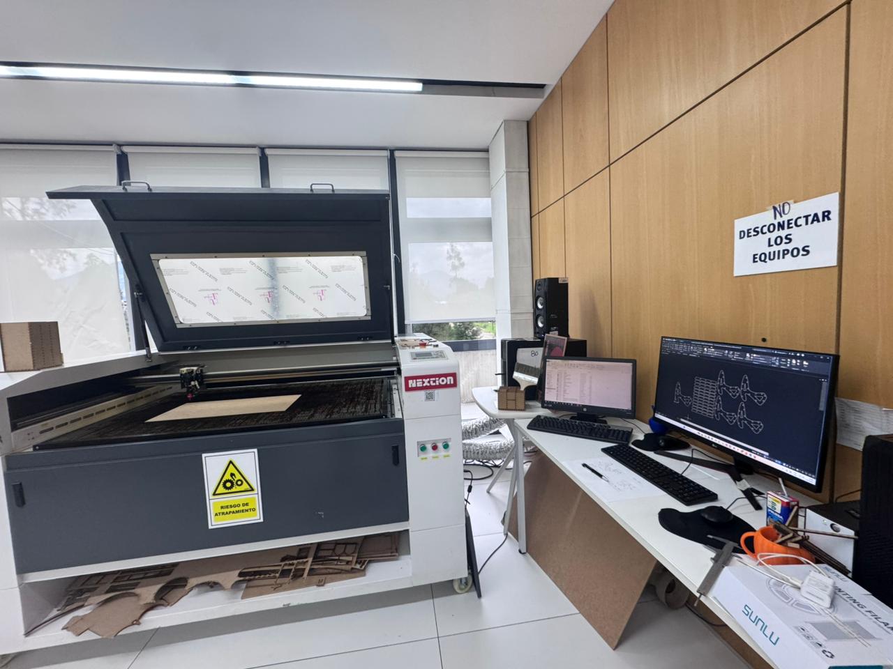
Fabrication was carried out using a 90W CO₂ laser cutting machine available at the Industrial FABLAB UCuenca, working with 5 mm MDF material.
4. Initial Sketch and Construction Plan
The design process started from a construction plan using a curvilinear drawing approach. An initial hand sketch was created on paper to define the basic geometry and dimensions of the assembly links before digital modeling.
This first sketch helped me visualize the possible shape of the pieces and understand how the elements could connect to each other. The idea was to create a flexible modular system that could be repeated and combined in different configurations.
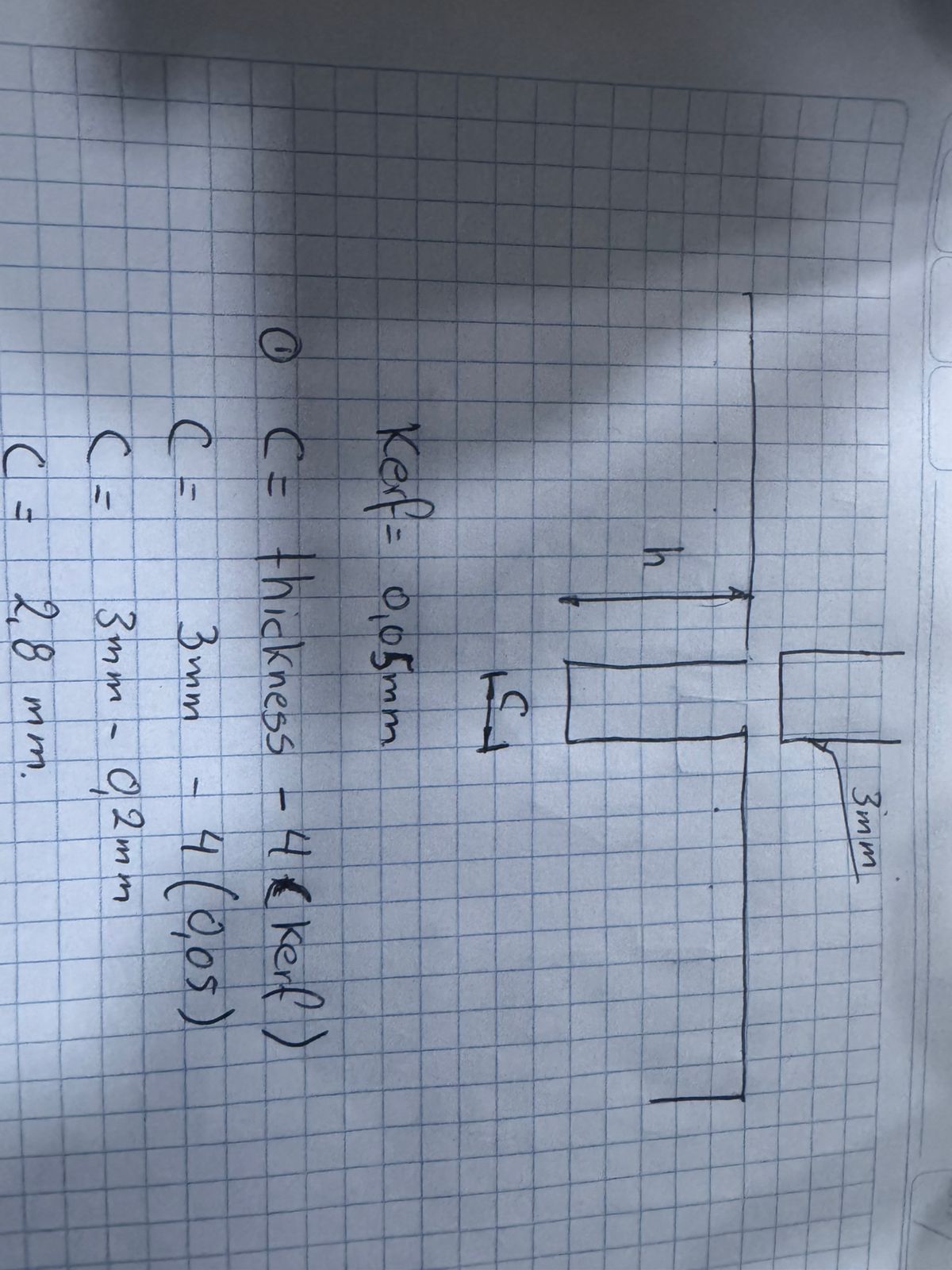
5. Kerf Calculation
To ensure a proper press-fit assembly, the kerf of the laser machine was calculated using a power and speed combination table. The best result was obtained with the following parameters, using the NEXTION CO₂ laser cutter:
- Power: 40 watts
- Speed: 40 mm/s
- Measured kerf: 0.05 mm
- Material: MDF, 5 mm thickness
These parameters were selected because they provided a clean cut and acceptable dimensional accuracy. The kerf value was later included in the Fusion 360 parameters to adjust the joint dimensions and improve the final assembly.
Kerf compensation is important because the laser removes a small amount of material during cutting. If this value is not considered, the slots can become too loose or too tight. In a press-fit system, this directly affects whether the pieces can be assembled by friction without glue.
5.1 Laser Cutter Characterization Reflection
The group characterization helped me understand how the main laser cutter parameters affect the final result. These tests were necessary before designing my individual press-fit kit because the quality of the joints depends directly on the real behavior of the machine and the material.
| Characterized Parameter | What I Learned | How It Affected My Individual Design |
|---|---|---|
| Focus | The laser must be focused correctly to obtain a clean and narrow cut. If the focus is incorrect, the cut becomes wider, less precise, or may not pass completely through the material. | I checked the focus before cutting my MDF pieces to improve edge quality and dimensional accuracy. |
| Power | Higher power increases the cutting capacity, but it can also burn the material or increase the kerf. Lower power may result in incomplete cuts. | I selected a power value that allowed the MDF to be cut without excessive burning. |
| Speed | Cutting speed affects how much energy is applied to the material. A slower speed increases cutting depth, while a faster speed may leave uncut areas. | I used the speed value identified during the group test to obtain complete and stable cuts. |
| Rate / Frequency | The rate or frequency influences how the laser pulses interact with the material. This can affect edge finishing and engraving or cutting quality depending on the machine configuration. | I considered this information when checking the cutting quality and avoiding excessive burning on the MDF edges. |
| Kerf | The kerf is the amount of material removed by the laser beam. In our test, the measured kerf was approximately 0.05 mm. | I included the kerf value as a parameter in Fusion 360 to compensate the press-fit joints. |
| Joint Clearance | The clearance defines how tight or loose the joint will be. A very small clearance can make the assembly difficult, while a very large clearance produces weak joints. | I adjusted the notch dimensions using the material thickness and kerf compensation to obtain a stable friction fit. |
| Types of Cuts and Joints | Different geometries behave differently. Straight slots, interlocking notches, and repeated modular joints require different tolerance considerations. | I used repeated parametric notches to create a modular construction kit that can be assembled in multiple ways. |
Based on this characterization, I understood that the design file alone is not enough to guarantee a good result. The final assembly depends on the relationship between material thickness, kerf, joint clearance, laser focus, power, speed, and the type of joint used in the construction kit.
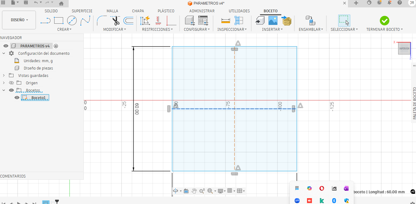
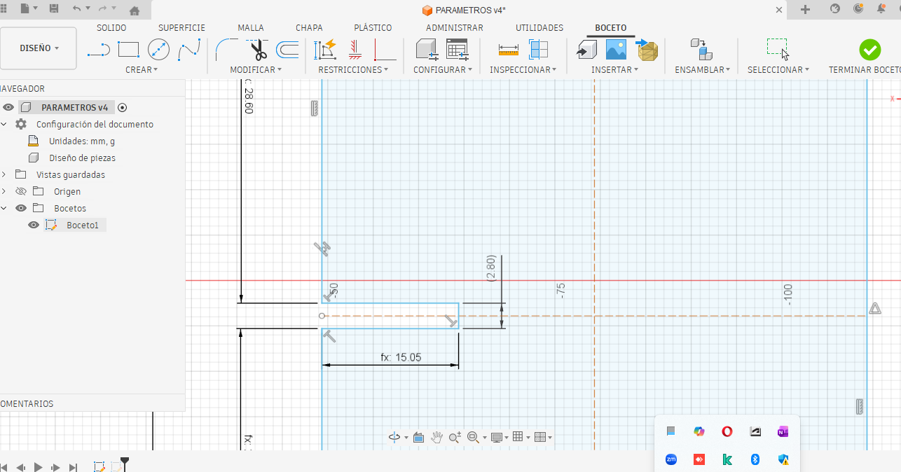
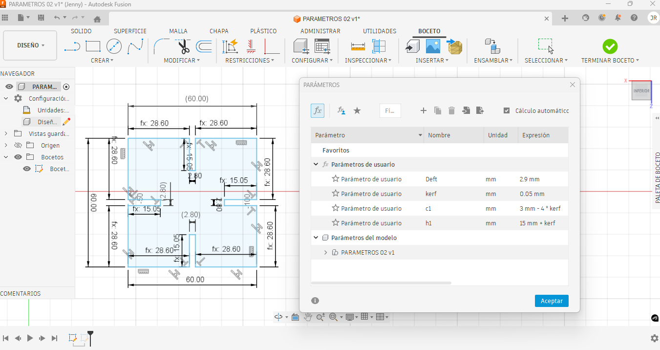
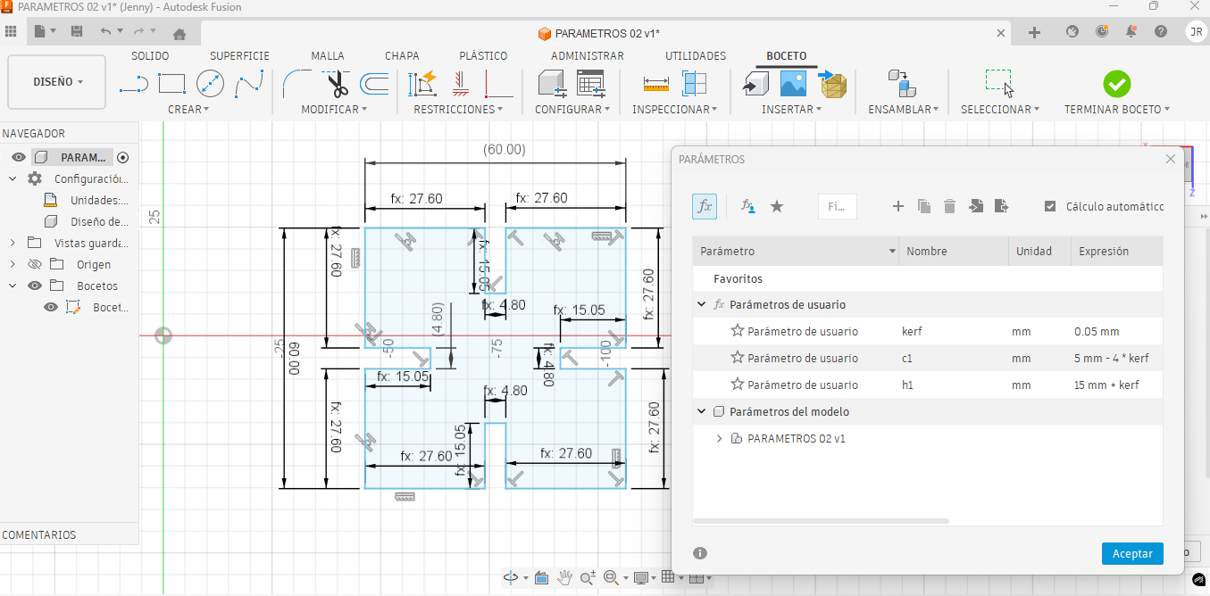
6. Parametric Variable Definition
Once the kerf value was defined, all key dimensions were parametrized in Fusion 360. This allowed the design to be modified by changing numerical values instead of redrawing the entire geometry. The most important editable parameters were material thickness, kerf, assembly height, slot width, and the working area of the piece.
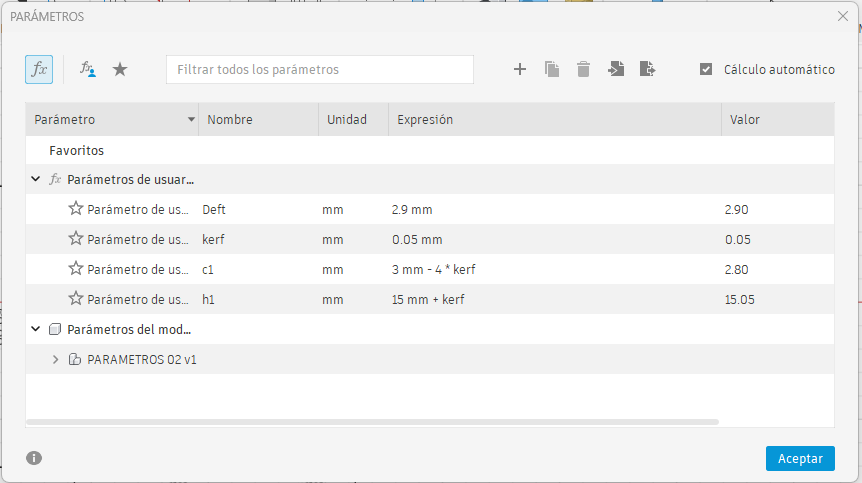
| Parameter | Value | Purpose in the Design |
|---|---|---|
| Material thickness | 5 mm | Defines the real thickness of the MDF sheet used for the press-fit joints. |
| KERF | 0.05 mm | Compensates the material removed by the laser beam during cutting. |
| h | Material thickness – 4 × kerf | Controls the effective slot dimension to improve the fit between parts. |
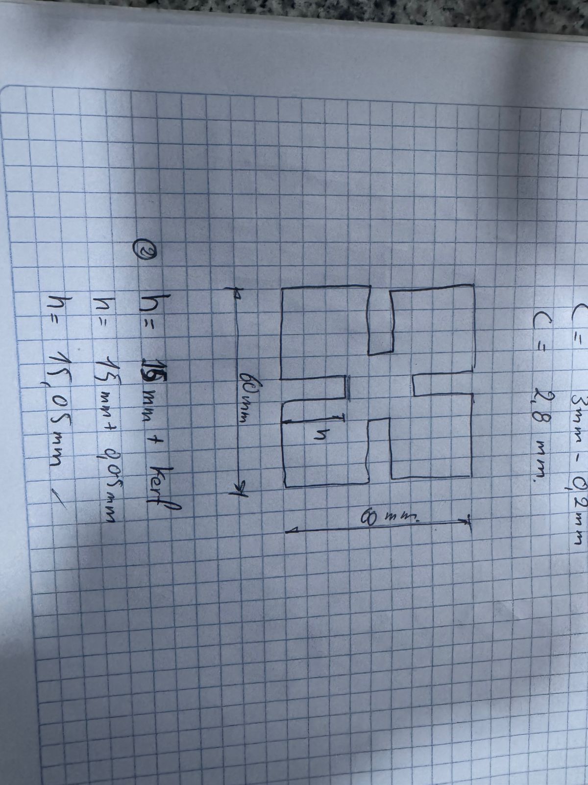
| Assembly height | 15 mm | Defines the reference height used for the interlocking connection. |
| y | Assembly height + kerf | Controls the position and spacing of the notch according to the kerf compensation. |
| Working area | 60 × 60 mm | Defines the maximum size of the modular piece. |
The link geometry was designed within a 60 × 60 mm working area. By using these parameters, the design can be adapted to another material thickness or another laser cutter by modifying only the parameter table in Fusion 360.
This parametric strategy helped me control the dimensions of the slots, maintain symmetry, and keep the same relationship between the body of the piece and the press-fit notches.
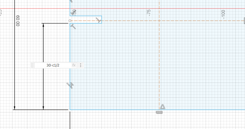
7. Constraints and Dimensional Control in Fusion 360
The model was controlled using geometric constraints and dimensional parameters. The constraints were important because they kept the geometry stable when values such as kerf or material thickness were changed.
- Symmetry constraints: used to keep the piece balanced around its central axis.
- Horizontal and vertical constraints: used to keep the slot and notch geometry aligned.
- Equal constraints: used to repeat similar slot dimensions in different areas of the design.
- Dimensional constraints: linked to user parameters such as kerf, material thickness, h, and y.
- Reference construction lines: used to position the notches in a controlled and repeatable way.
Instead of drawing fixed dimensions manually, the slots were linked to the parameter expressions. This means that if the MDF thickness changes from 5 mm to another value, the slot width can be recalculated automatically. This is useful in Fab Academy because the same design can be tested with different materials or different machines.
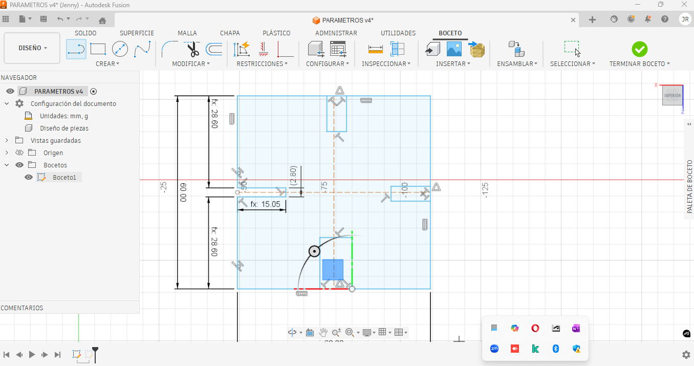
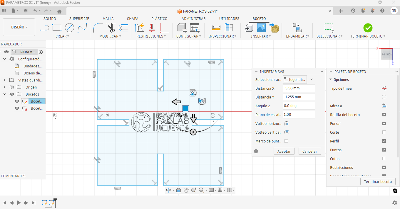
8. Parametric Joint and Notch Design
With the base geometry defined, the notches for the joints were drawn using a fully parametric approach. This allowed the joint dimensions to be adjusted automatically if the kerf, material, or thickness changed.
The notches were designed to generate enough friction between parts while still allowing manual assembly. This balance is important in press-fit systems because the parts must hold together firmly without breaking or becoming too difficult to assemble.
The slot width was controlled by the effective material thickness and kerf compensation. The goal was to avoid a loose joint caused by excessive material removal, while also avoiding a joint that was too tight and could damage the MDF during assembly.
9. Tolerance Referencing
All notches were referenced sequentially using the defined parameters and tolerances, ensuring repeatability and a consistent press-fit behavior throughout the assembly.
Tolerance referencing helped maintain the same joint behavior in all repeated elements. This is especially important in modular kits, where each piece must connect correctly with the rest of the system.
By referencing the notches to the same parameter values, I avoided having different slot sizes in the same design. This made the final assembly more predictable and easier to fabricate.
10. Crossbar Design
The crossbars that support and connect the structure were designed next, using the same parametric variables defined for the main link, maintaining coherence across the system.
These crossbars provide additional stability to the final assembly. Their dimensions were also linked to the parametric values to ensure that they could adapt to changes in material thickness and kerf compensation.
11. Material Thickness Simulation
A simulation was performed using a 5 mm thick material to validate the parametric behavior of the design before fabrication.
- KERF: 0.05 mm
- Material thickness: 5 mm
- Design area: 60 × 60 mm
- Assembly reference height: 15 mm
This simulation was useful to verify how the model would react if the material thickness changed. It confirmed that the parametric structure was working correctly and that the design could be adapted without redrawing the complete geometry.
12. Final Fabrication Setup
After validating the design, final fabrication was prepared by calibrating the laser cutter, paying special attention to the focus height.
The MDF sheet was placed on the machine bed, and the focus distance was adjusted before sending the job. The cutting file was checked to confirm that all lines were correctly defined and that there were no duplicated curves that could affect the cut.
The final cutting process followed these steps:
- Export the sketch from Fusion 360 as a DXF file.
- Open the vector file in the laser cutting software.
- Check scale, units, and line continuity.
- Remove duplicated or unnecessary lines.
- Place the MDF sheet on the laser bed.
- Adjust the focus of the CO₂ laser cutter.
- Set speed and power according to the group characterization test.
- Run the cutting job and verify that all pieces were fully cut.
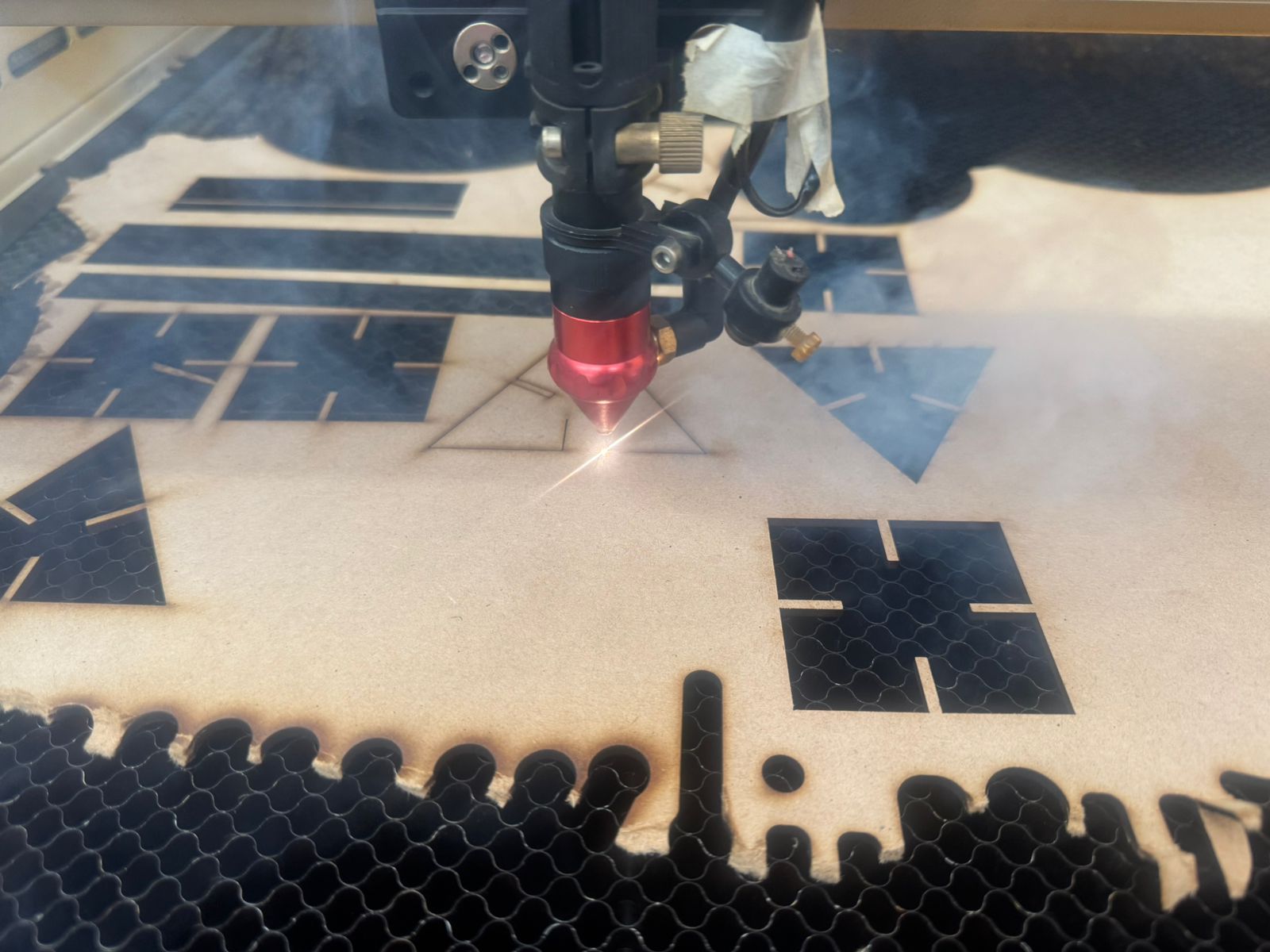
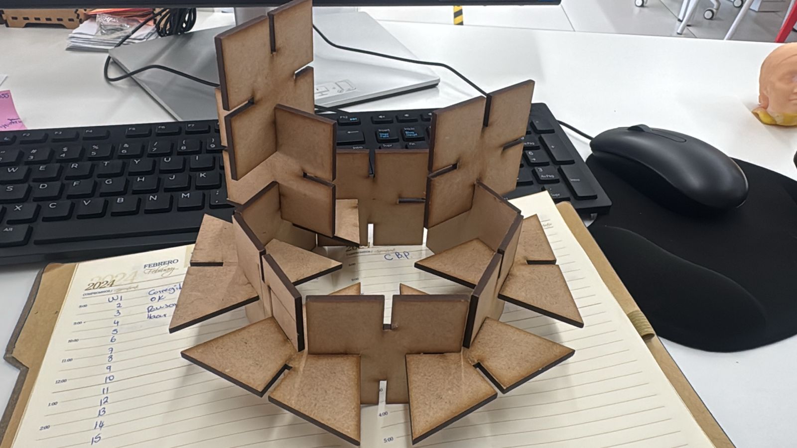
13. Final Assembly and Results
Once all parts were cut, the final assembly was carried out. The resulting product shows a strong press-fit behavior, correct kerf compensation, and does not require glue, which was a key requirement for this practice.
The final result confirmed that the parametric design strategy was effective. The pieces assembled correctly and maintained structural stability due to the friction generated by the press-fit joints.
This process also demonstrated the importance of testing, calibration, and iterative design in digital fabrication. By adjusting the kerf and tolerances, it was possible to improve the final fit and obtain a cleaner assembly.
14. Downloadable Files
The original design files are included below. These files allow the project to be reviewed, modified, and fabricated again. The Fusion 360 file contains the editable parametric model, while the DXF files contain the vector geometry used for laser cutting. The Illustrator file contains the vector design used for the vinyl cutting assignment.
Vinyl Cutting Assignment – Logo Design and Fabrication
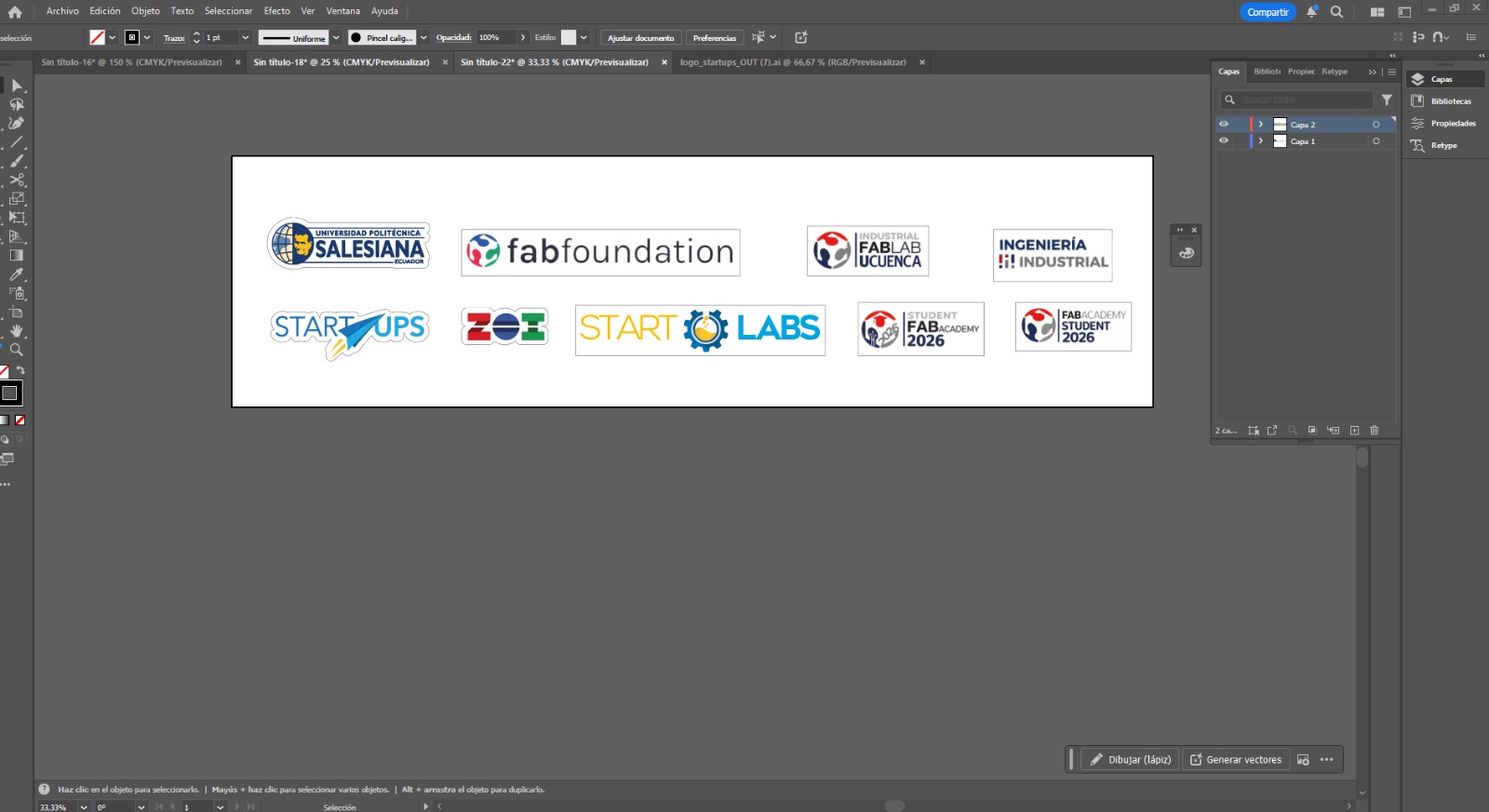
As part of this weekly assignment, we focused on the design and fabrication of custom logos using vinyl cutting techniques. The objective was to create and produce representative logos for each team and lab: Starlabs from Universidad Politécnica Salesiana, Industrial FABLAB from Universidad de Cuenca, and ZOILAB.
This activity allowed us to apply subtractive manufacturing processes on flexible materials such as adhesive vinyl, combining digital design with physical production. It also helped us understand the importance of preparing clean vector files, configuring the machine correctly, and carefully applying the final vinyl pieces.
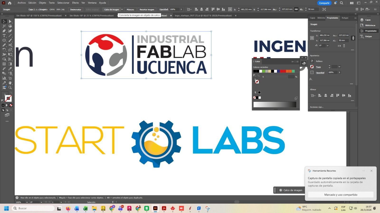
15. Design Preparation
Each logo was designed in vector format using CAD software, ensuring all elements were properly defined as clean paths. Since vinyl cutting requires vector geometry, special attention was given to eliminating duplicate lines and ensuring closed contours. The final designs were exported in compatible formats such as SVG, DXF, or AI.
The design preparation stage was important because the vinyl cutter follows the vector lines exactly. Any open contour, duplicated line, or unnecessary node can affect the quality of the final cut.
The editable vinyl cutting design file is included in the downloadable files section as cortevinil.ai. This file contains the vector artwork prepared for the vinyl cutter.
16. Machines Used
- Vinyl Cutter: Used to precisely cut the vector designs onto adhesive vinyl.
- Plotter: Used to support visualization and layout verification of the designs before cutting.
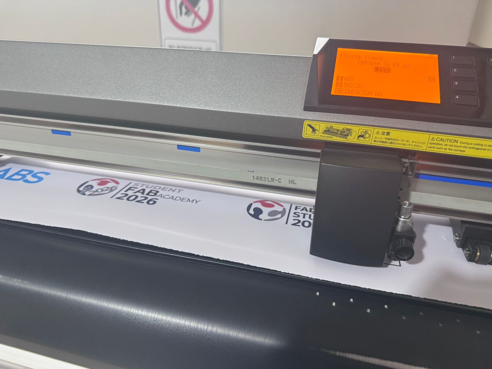
17. Machine Setup
- Loading the vinyl roll into the machine.
- Adjusting pinch rollers to secure the material.
- Setting the origin point.
- Configuring cutting parameters such as speed and force.
- Performing a small test cut before the final job.
17.1 Vinyl Cutter Settings
Before cutting the final logo, I checked the vinyl cutter settings to make sure the blade would cut only the adhesive vinyl layer and not the backing paper. A small test cut was useful to verify the blade depth, cutting force, and material movement.
| Setting | Purpose | Observation |
|---|---|---|
| Blade depth | Controls how deep the blade enters the vinyl. | The blade was adjusted to cut the vinyl layer without cutting through the backing paper. |
| Cutting force | Defines the pressure applied by the blade. | The force was checked with a test cut to avoid tearing the vinyl. |
| Cutting speed | Controls how fast the blade follows the vector paths. | A moderate speed was used to preserve small logo details. |
| Origin point | Defines where the machine starts cutting. | The origin was set after loading and aligning the vinyl roll. |
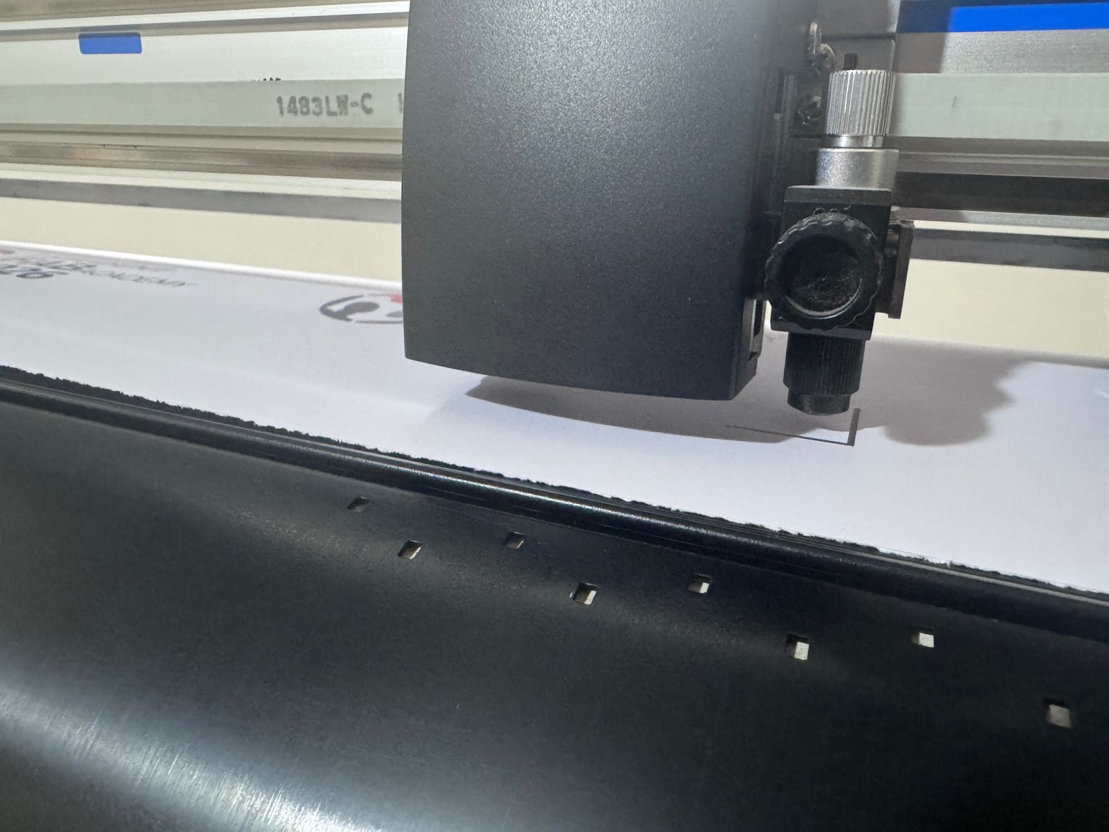
18. Cutting Process
The design was sent to the vinyl cutter, where the blade precisely followed the vector paths. Care was taken to ensure the cutting depth was sufficient to cut the vinyl layer without damaging the backing material.
The cutting force and speed were checked before the final cut to avoid tearing the vinyl or producing incomplete cuts. This step was especially important for small details and thin lines in the logos.
19. Weeding Process – Removing Excess Vinyl
After cutting, the excess vinyl was removed manually in a process called weeding. This step was necessary to separate the final logo from the surrounding vinyl sheet. I carefully removed the unused vinyl areas while keeping the small internal details attached to the backing paper.
The weeding process required patience and precision because thin lines or small letters can be accidentally removed. For this reason, I used manual tools to lift the unwanted parts slowly, checking that the final design remained complete.
This step is important because the quality of the final sticker depends not only on the machine cut, but also on the correct manual removal of the unnecessary vinyl.
20. Transfer Tape Application
Once the unwanted vinyl was removed, transfer tape was applied over the logo. The purpose of the transfer tape was to keep all parts of the design aligned while moving the sticker from the backing paper to the final surface.
I placed the transfer tape over the vinyl and pressed it carefully to make sure the design adhered correctly. Then, the backing paper was removed slowly, checking that the vinyl stayed attached to the transfer tape.
This step is especially important for logos because it preserves the correct position of each graphic element during application.
21. Final Application on the Surface
The final surface was cleaned before applying the vinyl sticker. Then, the transfer tape with the logo was aligned and placed on the surface. Pressure was applied from the center to the edges to avoid bubbles and improve adhesion.
After the vinyl adhered to the surface, the transfer tape was removed slowly at a low angle. This allowed the vinyl logo to remain fixed on the final surface without lifting small details.
The final result showed clean edges, correct adhesion, and good visual quality. This completed the full vinyl cutting workflow: vector design, machine setup, cutting, weeding, transfer tape application, and final installation.
22. Vinyl Cutting Result
This assignment demonstrates the workflow from digital design to physical output using a vinyl cutter, highlighting precision, material handling, and finishing techniques. The process also showed how vinyl cutting can be used for branding, signage, personalization, and visual communication inside a FabLab environment.
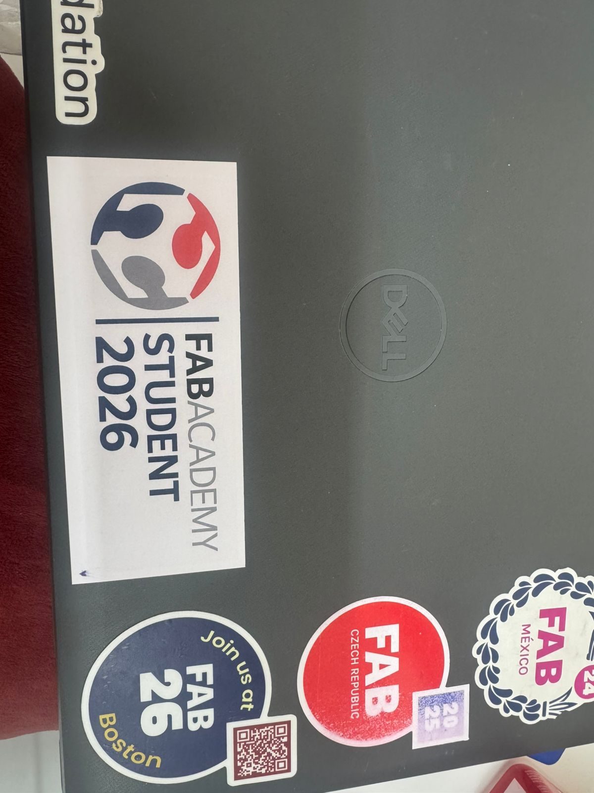
Hero Shot
The following hero shot presents the final result of the vinyl cutting assignment developed during Week 03. This activity focused on the fabrication of customized institutional logos using adhesive vinyl and computer-controlled cutting technologies.
The final application demonstrates the precision achieved through vector-based design, machine calibration, material preparation, careful weeding, transfer tape application, and final placement on the selected surface.
Final Conclusion
This week helped me understand computer-controlled cutting as a complete digital fabrication process, where the final result depends on the relationship between design, machine calibration, material behavior, safety procedures, and post-processing. Through the group assignment, I learned how important it is to characterize the laser cutter before fabricating a final object. Testing focus, power, speed, rate, kerf, joint clearance, and material response allowed us to identify reliable parameters for cutting MDF with better precision and less burning.
The group characterization was directly useful for my individual assignment because it gave me technical information that I applied to my parametric construction kit. Designing the kit in Fusion 360 helped me understand that a press-fit system depends not only on the shape of the pieces, but also on material thickness, kerf compensation, joint clearance, and dimensional control. By using editable parameters, I was able to create a flexible and adaptable model that can be modified for different materials or laser cutter settings without redrawing the entire design.
During the laser cutting process, I learned that small variations in focus, power, speed, or kerf can significantly affect the quality of the cut and the fit between parts. The final construction kit showed a stable press-fit behavior and could be assembled without glue or screws, which confirmed the importance of testing, calibration, and tolerance adjustment in digital fabrication.
In the vinyl cutting activity, I learned that the process does not finish when the machine cuts the design. The final result also depends on preparing a clean vector file, configuring the vinyl cutter correctly, removing the excess vinyl, applying transfer tape, and placing the sticker carefully on the final surface. This helped me understand that post-processing is an essential part of computer-controlled cutting.
Overall, this assignment allowed me to connect group testing with individual design decisions. I learned to evaluate machine parameters, design with tolerances, document the fabrication workflow, and produce physical results that are functional, repeatable, and visually clear.