1. Project Overview
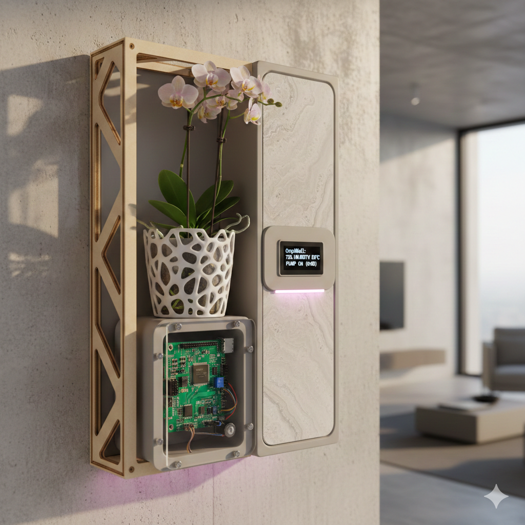
OrquiWall Smart System is a modular, wall-embedded intelligent orchid cultivation module designed to automate irrigation, monitor environmental variables, and integrate seamlessly into architectural spaces.
The project addresses the intersection between digital fabrication, embedded electronics, parametric design, and biophilic architecture. It is developed following the Design Thinking methodology and structured to integrate multiple Fab Academy assignments into a single cohesive bio-digital system.
The system combines:
- Automated irrigation control
- Substrate moisture monitoring
- Environmental sensing (temperature and humidity)
- Integrated user control panel
- Parametric and adaptable mechanical design
- Digital fabrication workflows (additive and subtractive)
Target Users
- Orchid enthusiasts
- Home users interested in smart gardening
- Interior designers integrating biophilic elements
- Smart home technology adopters
2. Problem Statement
Orchids are epiphytic plants with highly specialized biological requirements. Their survival depends on:
- Precise substrate humidity control
- Avoidance of waterlogging
- Continuous root ventilation
- Stable ambient conditions
Current Challenges
- Overwatering (primary cause of orchid death)
- Lack of real-time humidity measurement
- Manual, experience-dependent care
- Non-aesthetic commercial solutions
- No architectural integration
Existing commercial systems such as Click and Grow provide automated indoor gardening, but they are:
- Not designed specifically for orchid biology
- Not optimized for root aeration
- Not architecturally embedded
- Not customizable through digital fabrication
There is currently no wall-integrated intelligent orchid care system that combines precision irrigation, parametric fabrication, and aesthetic architectural design.
3. Design Thinking Methodology
1. Empathize
Urban environments reduce optimal conditions for orchid growth. Many orchid collectors and botanical enthusiasts struggle with humidity, light control, and irrigation stability. Through observation and interviews, a need for a controlled vertical smart garden was identified.
2. Define
Problem Statement: Design and fabricate a modular smart wall system capable of monitoring and controlling environmental variables such as humidity, temperature, irrigation cycles, and lighting conditions for orchids.
- Modular expandable panels
- Low energy consumption
- Integrated sensor network
- Automated irrigation
- Smart monitoring interface
3. Ideate
Concept development included:
- Stackable structural modules
- Custom PCB with environmental sensors
- Water distribution channel system
- Mobile monitoring via WiFi
4. Prototype
Rapid prototyping using 3D printed structural supports and laser-cut backing panels. Tolerance adjustments were applied using parametric modeling.
Initial Prototypes
Structural Prototype

Electronics Integration Prototype
Irrigation System Prototype
5. Test
- Humidity sensor calibration
- Water pump cycle validation
- Lighting intensity testing
- Structural resistance verification
- Power consumption measurement
4. Technical Specifications
Mechanical Specifications
- Wall-embedded niche module
- Parametric adaptable dimensions
- Internal drainage management
- Root ventilation channels
Electronic Specifications
- ESP32
- Capacitive moisture sensor
- DHT22
- Micro pump
- LED grow light
Functional Specifications
- Automatic irrigation
- Manual override
- Environmental monitoring
- Water level alert
5. System Architecture
- Sensing layer
- Processing layer
- Actuation layer
- Interface layer
- Communication layer
6. Bill of Materials (BOM)
| Component | Function | Fabricated / Purchased |
|---|---|---|
| ESP32 | Main controller | Purchased |
| Custom PCB | Electronic integration | Fabricated (Milling) |
| Moisture Sensor | Humidity measurement | Purchased |
| DHT22 | Temp & humidity | Purchased |
| Micro Pump | Irrigation | Purchased |
| 3D Printed Pot | Root ventilation | Fabricated |
| Laser Cut Frame | Structure | Fabricated |
| OLED Display | User interface | Purchased |
7. Parts to Fabricate
| Part | Process | Fab Academy Assignment |
|---|---|---|
| Wall Frame | Laser Cutting | Computer-Controlled Cutting |
| Orchid Pot | 3D Printing | 3D Printing |
| PCB | PCB Milling | Electronics Production |
| Front Panel | Molding & Casting | Molding and Casting |
8. Fab Academy Assignments Involved
| Week | Assignment | Application |
|---|---|---|
| Week 01 | Project Management | Documentation |
| Week 02 | CAD | Parametric modeling |
| Week 03 | Cutting | Frame fabrication |
| Week 04 | Electronics | PCB fabrication |
| Week 07 | Embedded Programming | Firmware |
| Week 14 | Final Integration | Testing |
9. Fab Academy Integration
The OrquiWall Smart System integrates several Fab Academy assignments into one final prototype. Each assignment contributed a specific layer of the system: documentation, design, fabrication, electronics, programming, mechanical movement, sensing, output control, and final integration.
| Fab Academy Assignment | Final Project Application | Evidence in OrquiWall |
|---|---|---|
| Project Management | Website documentation and versioned project development | Final project page, weekly documentation, downloadable files, and process evidence. |
| Computer-Aided Design | 3D modeling and parametric design of the wall frame, pot, supports, and cases | Fusion 360 models for the organic frame, water pot, wiring case, and motor supports. |
| Computer-Controlled Cutting | Fabrication of the MDF sliced wall frame | DXF cutting files, laser-cut MDF ribs, press-fit assembly, and organic sliced framework. |
| 3D Printing | Printed functional components for biological and mechanical integration | PLA water pot, orchid planter elements, motor supports, bearing holders, and wiring case. |
| Electronics Production | Custom PCB for the control system | KiCad schematic, PCB layout, fiber laser PCB fabrication, drilling, soldering, and continuity tests. |
| Embedded Programming | Control logic for irrigation and motor movement | Irrigation system code for ESP32 XIAO C3, motor control, sensor reading, and system behavior. |
| Input Devices | Environmental and position sensing | Humidity sensor for plant/substrate monitoring and two limit switches for movement references. |
| Output Devices | Actuation and visual feedback | A4988 driver, 12-15 V stepper motor, 40 cm lead screw movement, and LCD display interface. |
| Mechanical Design | Motorized vertical mechanism and component assembly | Stepper motor, lead screw, bearing support, guide rods, printed holders, reservoir movement tests. |
| System Integration | Connection between fabricated structure, electronics, water system, and orchid pot | Final assembly with MDF frame, PCB, wiring case, LCD, reservoir, orchid pot, sensor cables, and final test video. |
| Applications and Implications | Definition of the product purpose, user need, and system impact | Biophilic wall module for orchid care, integrating irrigation, sensing, movement, and fabrication. |
| Invention, Intellectual Property and Income | Open documentation and future development strategy | Downloadable fabrication files, documented workflow, and scalable design for future wall garden modules. |
This integration map shows how the final project works as a complete Fab Academy synthesis: the object is digitally designed, digitally fabricated, electronically controlled, mechanically actuated, biologically validated, and documented for reproduction.
10. Impact and Innovation
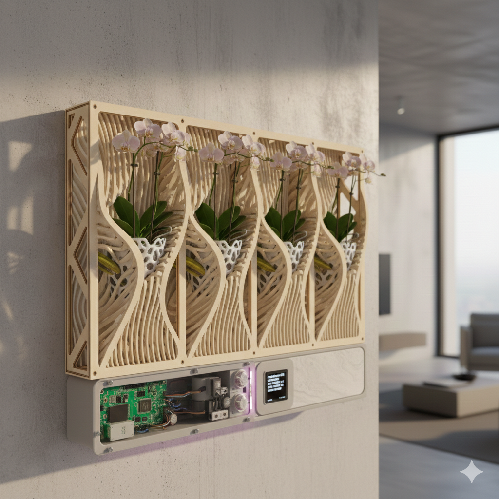
- Wall-integrated smart orchid care
- Parametric modular fabrication
- Fully digital workflow
- Open-source philosophy
- Scalable to vertical gardens
Integration of architecture, embedded electronics, digital fabrication, environmental sensing, and IoT systems into a single intelligent bio-digital product aligned with Fab Academy requirements.
11. Wall Frame Development: Computer-Aided Design & Computer-Controlled Cutting
The wall frame is the main structural element of the OrquiWall Smart System. It was developed as a press-fit MDF structure made from serial sliced pieces, combining an organic visual language with a fabrication workflow suitable for computer-controlled cutting.
The frame was designed to be mounted vertically on the wall, with an approximate final size of 60 cm in height by 20 cm in width. Its curved profile was intentionally shaped to avoid a rigid rectangular appearance and to simulate a more organic structure, closer to the movement of natural stems or roots.
Design Goal
Create a lightweight wall structure with repeated MDF slices and an organic silhouette.
Material
MDF sheet with a calibrated thickness of 5.5 mm for press-fit assembly.
Dimensions
Final wall frame scale: 60 cm high x 20 cm wide.
Assembly
The pieces are assembled by pressure using interlocking slots generated from the slicer workflow.
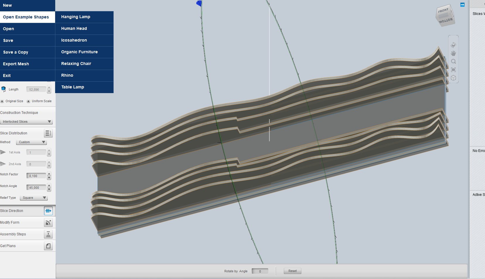
1. CAD Modeling in Fusion 360
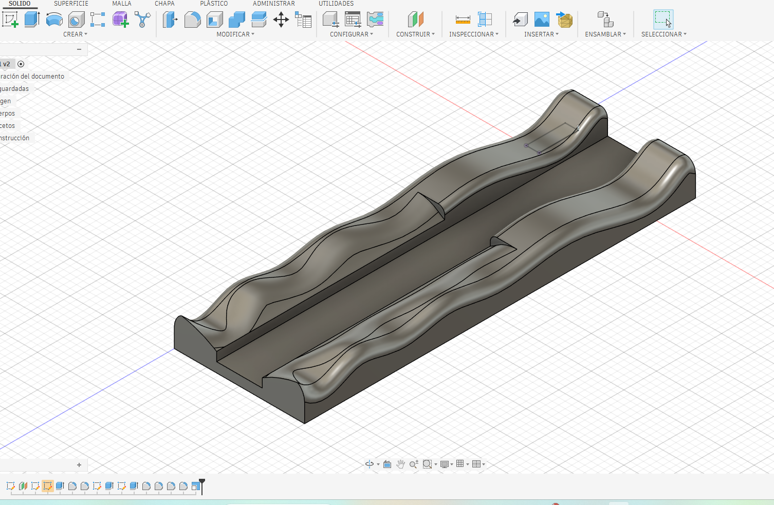
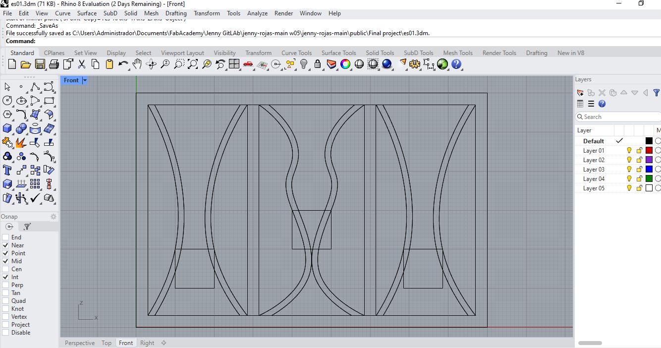
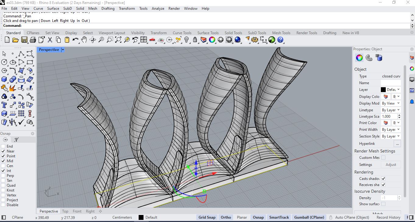
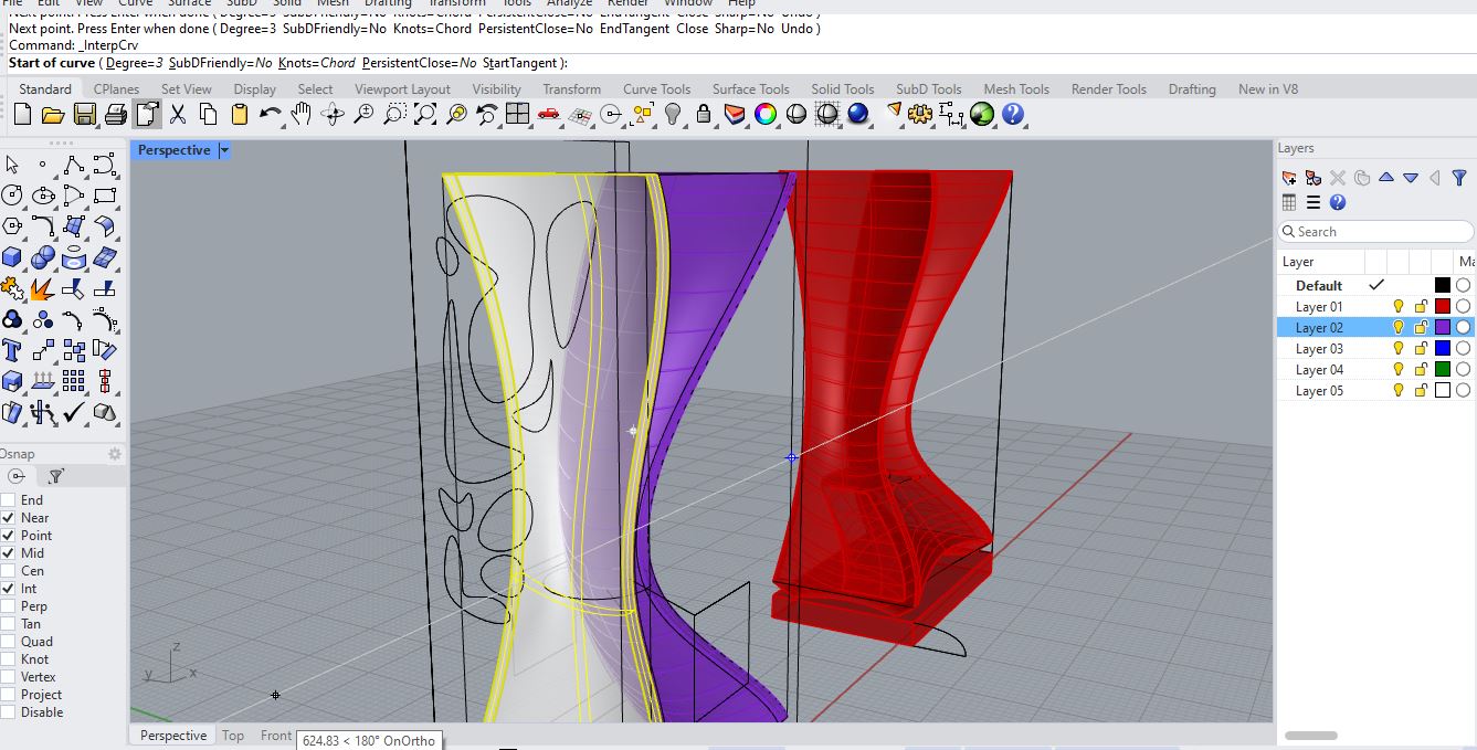
The process started in Fusion 360, where the base volume of the wall frame was modeled as a solid. The geometry was developed from a long rectangular body and then modified with curved side profiles. These curves define the organic aesthetic of the structure and also guide the later slicing process.
Instead of designing each cut piece manually, the project first established the complete 3D volume. This made it possible to evaluate proportions, curvature, structural continuity, and the final visual direction before preparing the object for digital fabrication.
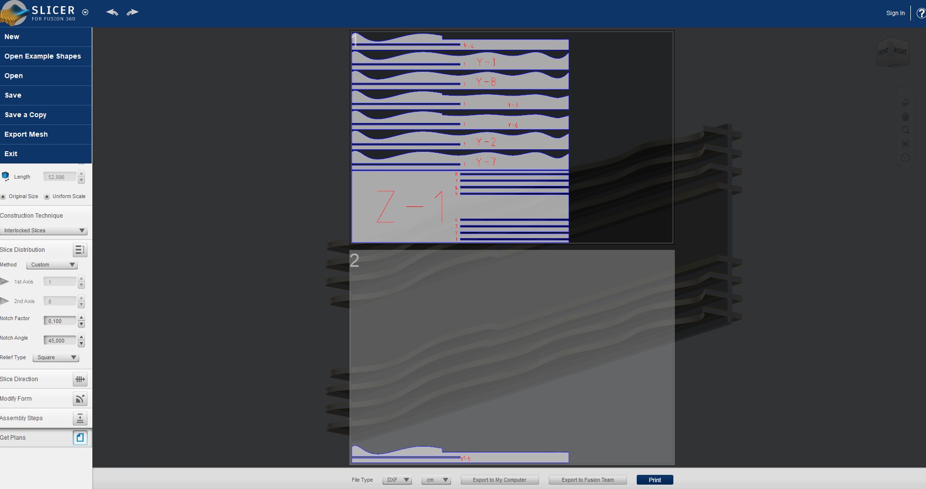
2. Solid Preparation for Slicer for Fusion 360
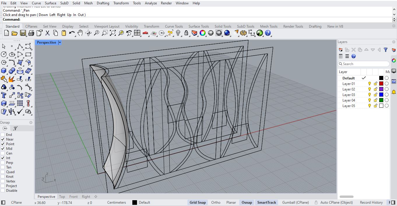
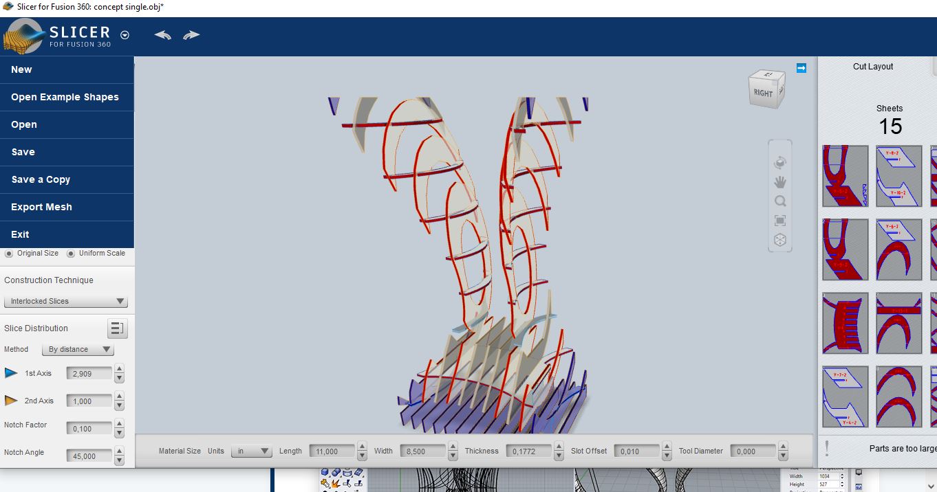
After defining the main volume, the solid was prepared for Slicer for Fusion 360. This step transformed the 3D model into a construction system made of interlocked slices. The selected strategy was based on serial pieces because it allowed the frame to keep its organic profile while being fabricated from flat MDF sheets.
The slicing setup was adjusted to the real material thickness. The MDF measured 5.5 mm, so the slots and slice spacing were parametrized around this value. This calibration is important because the final frame does not use screws or glue as the main fixing method; the mechanical stability depends on the pressure-fit between the pieces.
3. Parametric Material Setup
The Slicer file was configured with the MDF thickness as the main fabrication parameter. The material thickness was set to 5.5 mm, and the interlocking construction method generated the slot system for assembly. This made the digital model directly connected to the physical material available in the lab.
- Software: Fusion 360 and Slicer for Fusion 360
- Construction method: Interlocked slices
- Material: MDF
- Material thickness: 5.5 mm
- Assembly method: Press-fit slots
- Final frame size: 60 cm x 20 cm
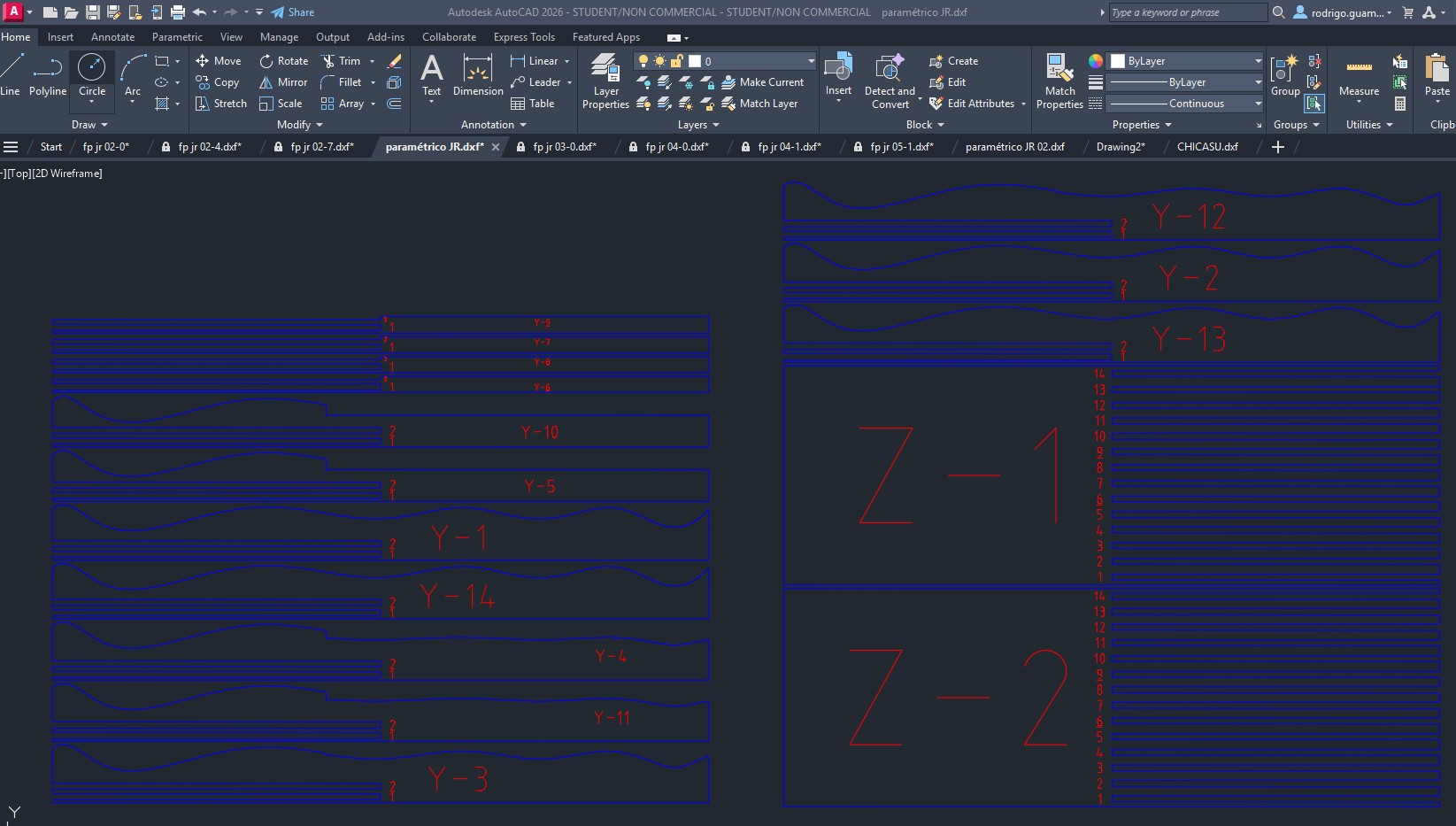
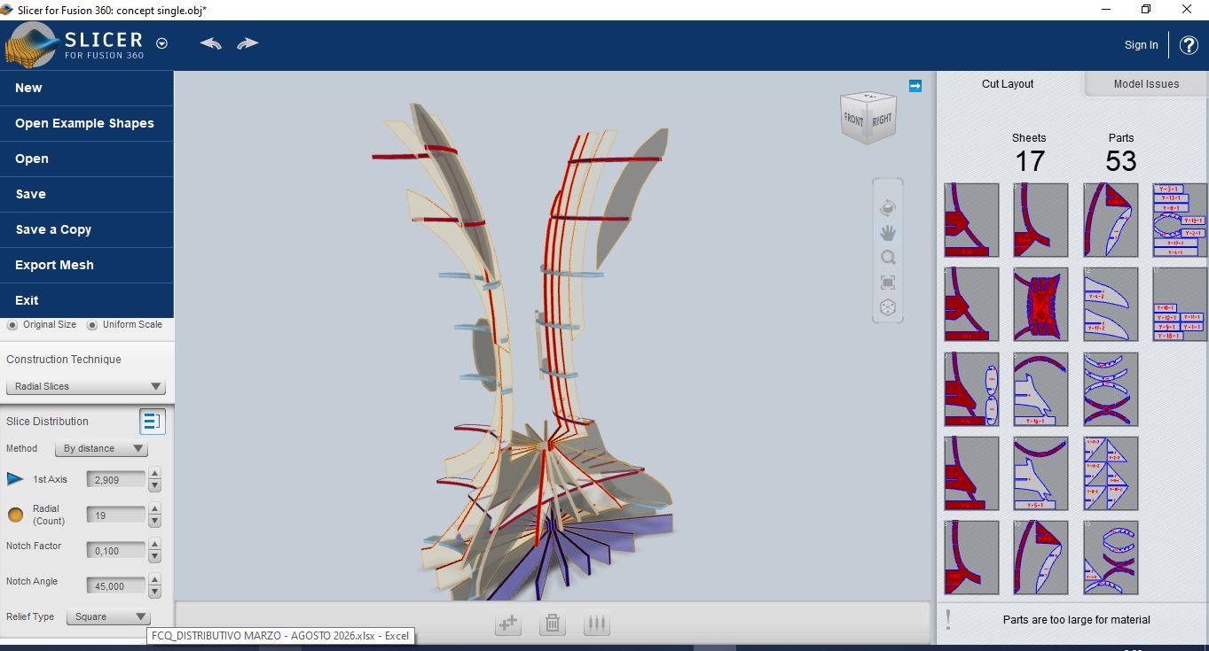
4. Cutting Layout and DXF Export
Once the slicing strategy was validated, the cutting plans were exported as DXF files. The layout contains the numbered serial pieces, including the longitudinal and transverse components required to assemble the frame. The labels help identify the order and orientation of each piece during assembly.
The exported drawing was checked in AutoCAD before fabrication. This verification step made it possible to confirm that the cutting lines were clean, the pieces were organized on the sheet, and the slots corresponded to the MDF thickness used for the press-fit construction.
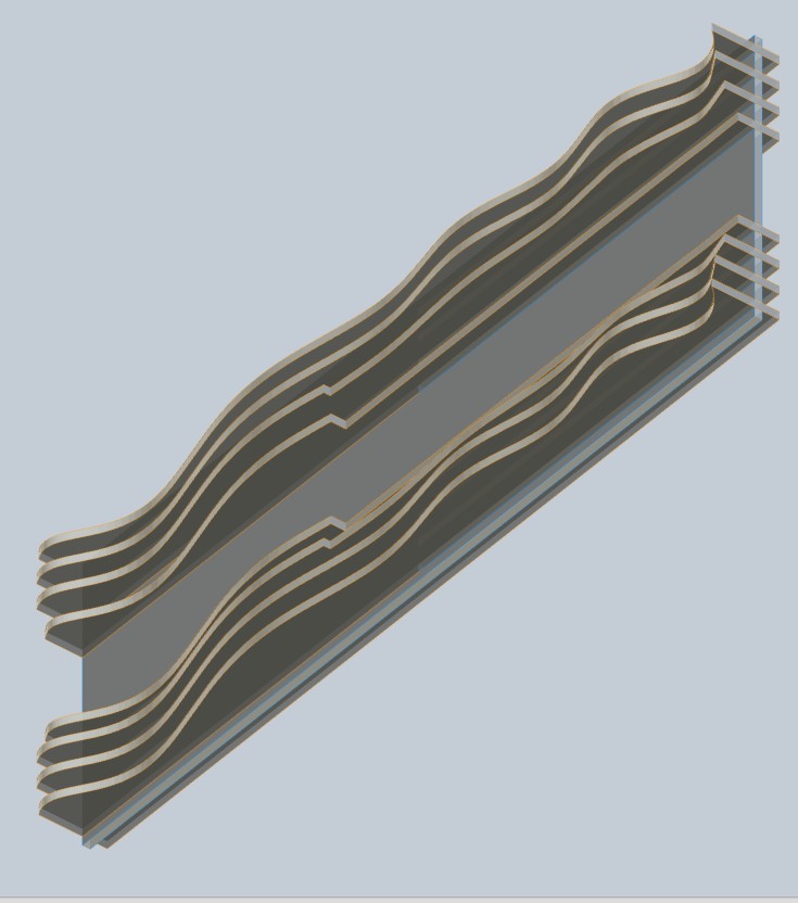
5. Fabrication Logic
The final frame is built from flat MDF pieces that gain volume through assembly. The repeated slices create a layered edge condition, while the curved profiles generate the organic visual effect. This strategy reduces the need for complex 3D machining and makes the structure reproducible using standard computer-controlled cutting.
Because the frame depends on pressure-fit joints, the main design constraint was the relationship between slot size, material thickness, and cutting tolerance. The 5.5 mm MDF parameter was therefore maintained throughout the Slicer setup and the exported DXF file.
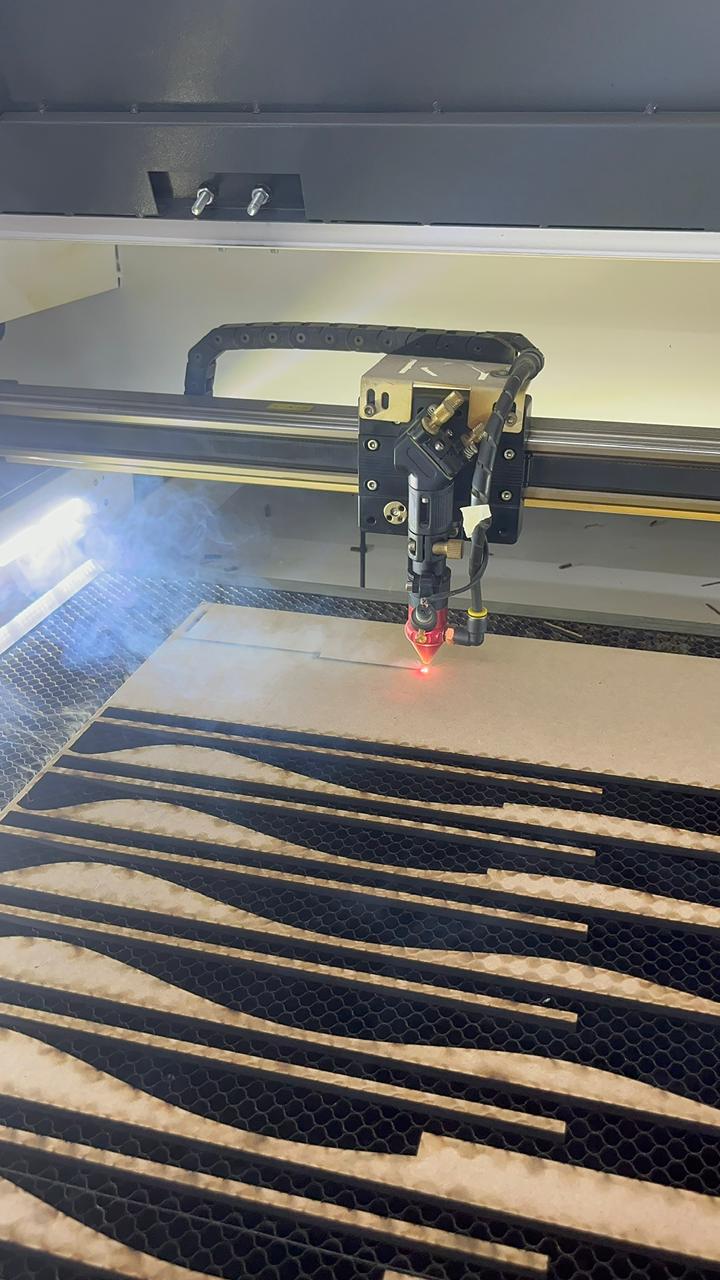
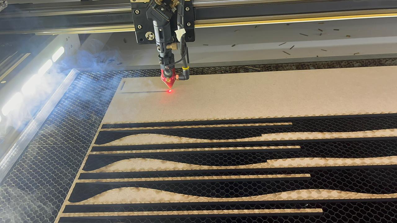
6. Laser Cutting Process
After exporting the DXF cutting plans, the file was prepared for laser cutting. The main objective in this stage was to keep the serial pieces organized and to preserve the exact slot geometry generated in Slicer for Fusion 360. Since the frame works as a press-fit assembly, any variation in the slot width could make the structure too loose or too tight.
The MDF sheet was placed on the honeycomb bed of the laser cutter and the cutting job was started from the vector layout. The laser followed the organic contours of the side pieces and the long structural components. During the cut, special attention was paid to the thin areas of the serial slices, because these pieces define both the visual rhythm and the final stiffness of the frame.
Cutting considerations
- The cutting lines were kept as clean vector paths to avoid double cutting.
- The MDF thickness was checked before fabrication and used as the main press-fit reference.
- The pieces were not removed immediately until the cut path was complete, preventing small elements from moving inside the machine.
- The dark laser-burned edge was accepted as part of the visual contrast of the layered organic frame.
- The numbered pieces from the Slicer layout were kept in order to simplify assembly.
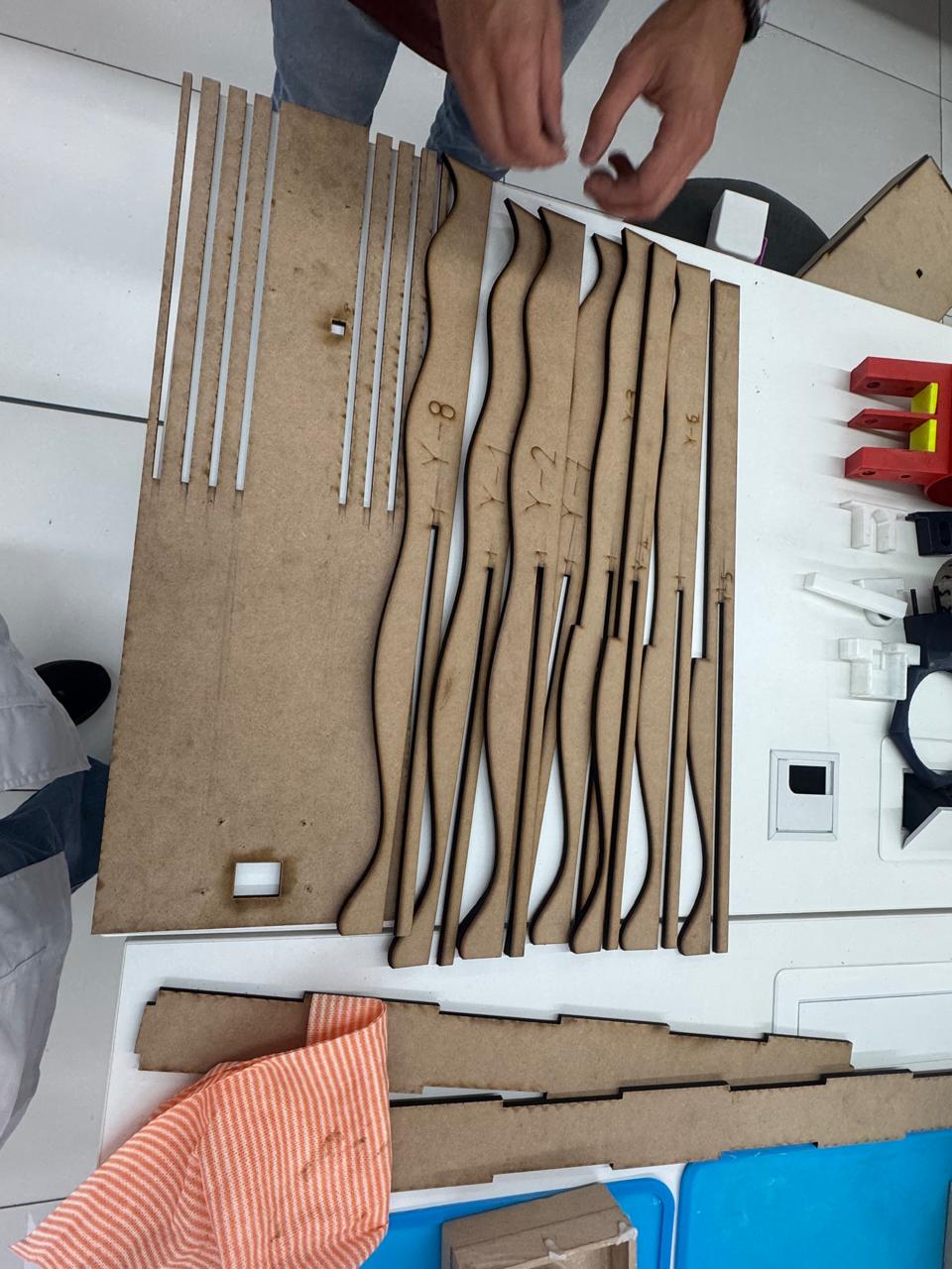
7. Sorting and Preparing the Cut Pieces
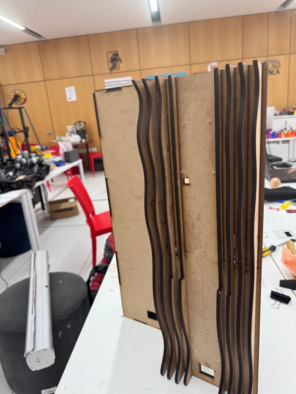
Once the laser cutting process finished, the MDF parts were removed from the sheet and organized on the worktable. The frame contains two main types of components: the flat structural plates that define the back support, and the repeated organic slices that create the visible side profile. The pieces were grouped according to their position and orientation before starting the assembly.
This sorting step was important because many pieces have similar dimensions but slightly different curves. The serial order generated by the slicing software allowed the structure to grow gradually from one side to the other, keeping the organic surface continuous.
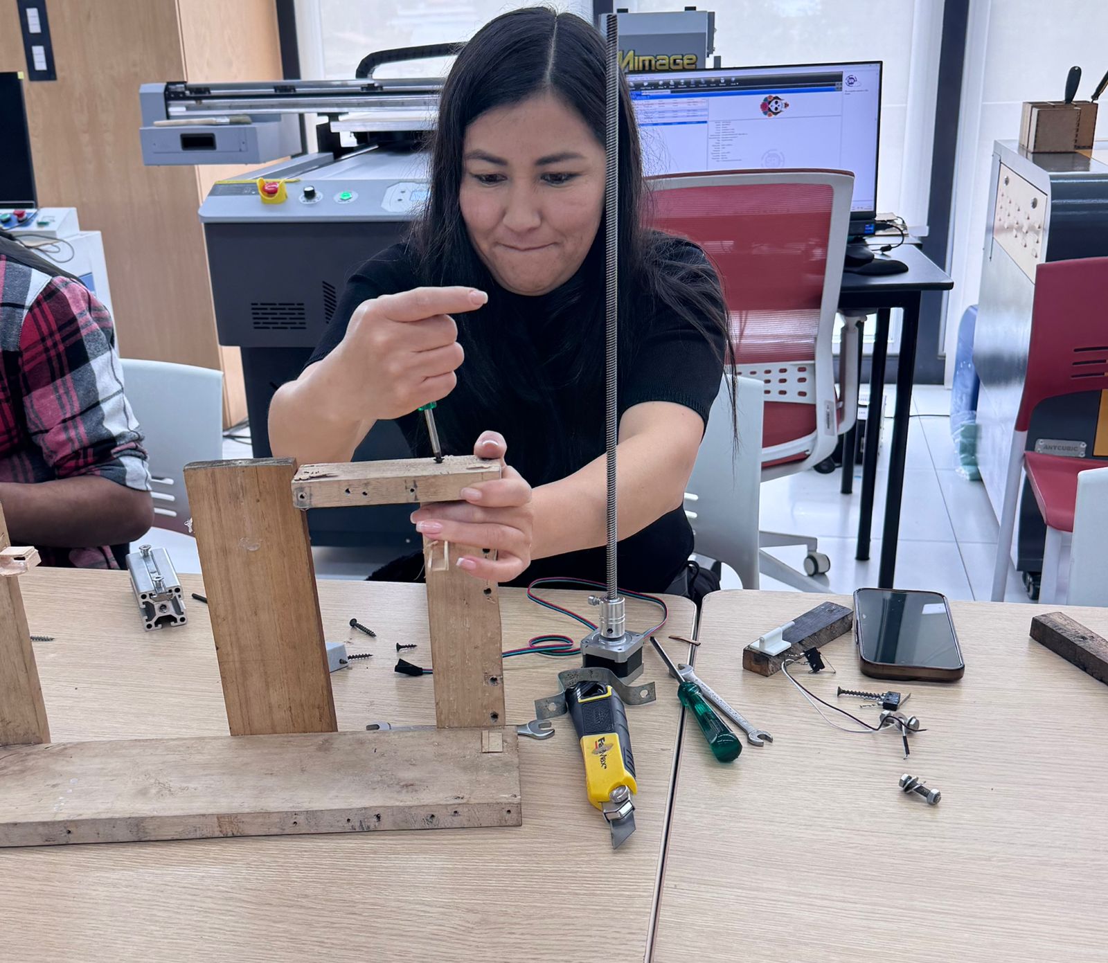
8. Press-Fit Assembly
The assembly was done manually by inserting the MDF elements into their corresponding slots. The structure was designed to be assembled by pressure, so each joint had to enter firmly without breaking the material. The long base pieces were used as alignment guides, while the vertical and organic slices were added progressively.
During the first assembly test, the fit between parts was checked carefully. Some joints required light pressure by hand to seat completely. This confirmed that the 5.5 mm material parameter was close to the real MDF behavior after laser cutting. The burned edges also slightly affected friction, helping some pieces lock more tightly in place.

Assembly sequence
- Identify the parts: separate the back plates, side ribs, long spacers, and small locking elements.
- Start from the base structure: align the long pieces and insert the first ribs into the slots.
- Build the organic side profile: place the serial slices in order so the curves remain continuous.
- Check perpendicularity: verify that the back plate and the side slices remain vertical during assembly.
- Apply controlled pressure: push each joint until it reaches the bottom of the slot without forcing the MDF fibers.
- Test stability: stand the frame upright and check if it keeps its shape without opening at the joints.
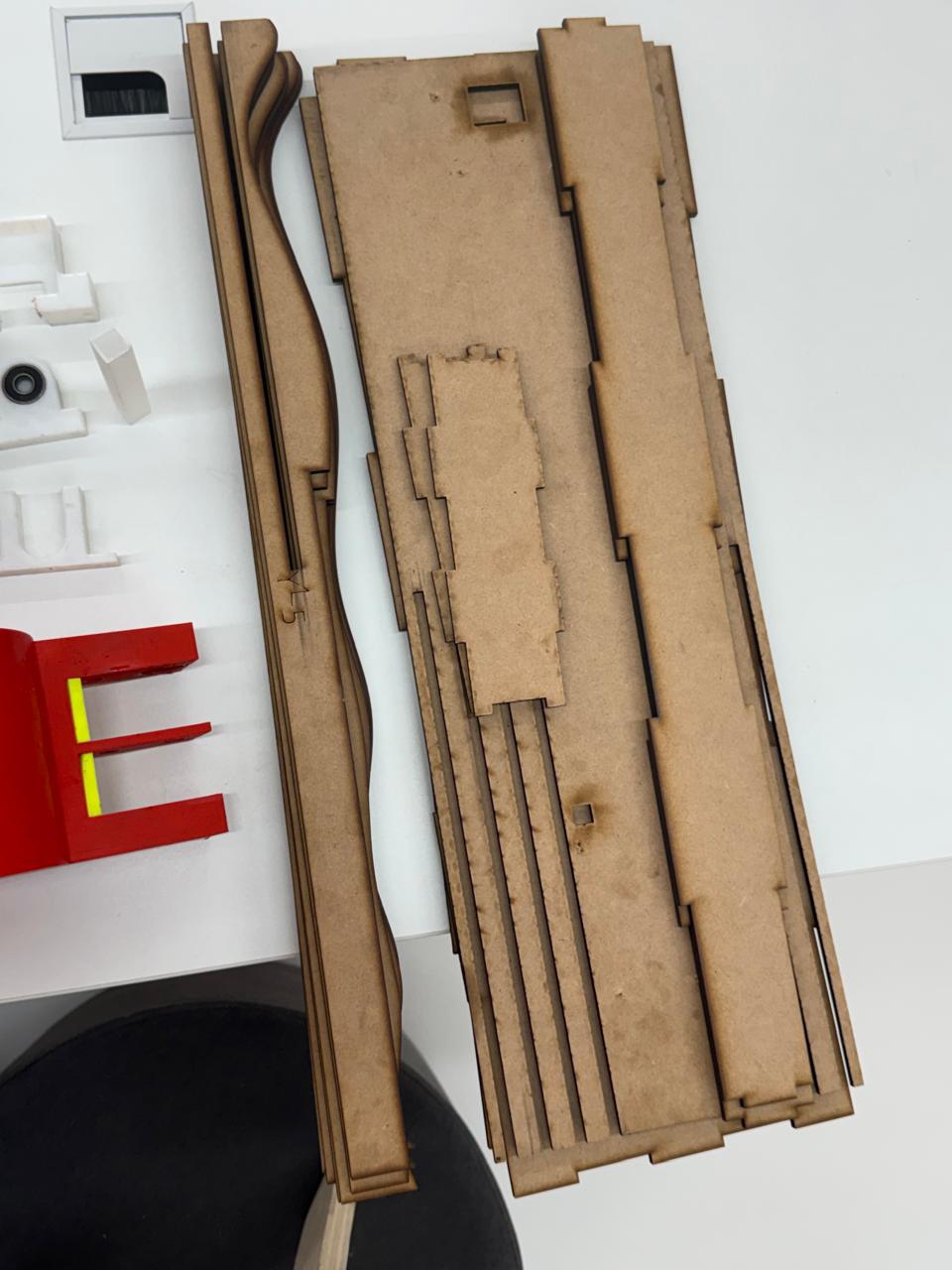
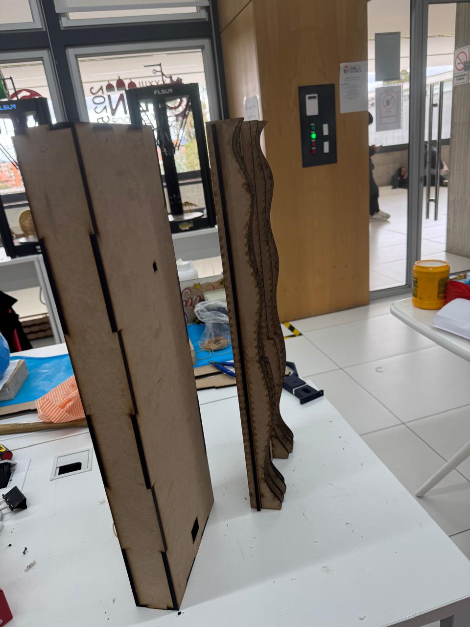
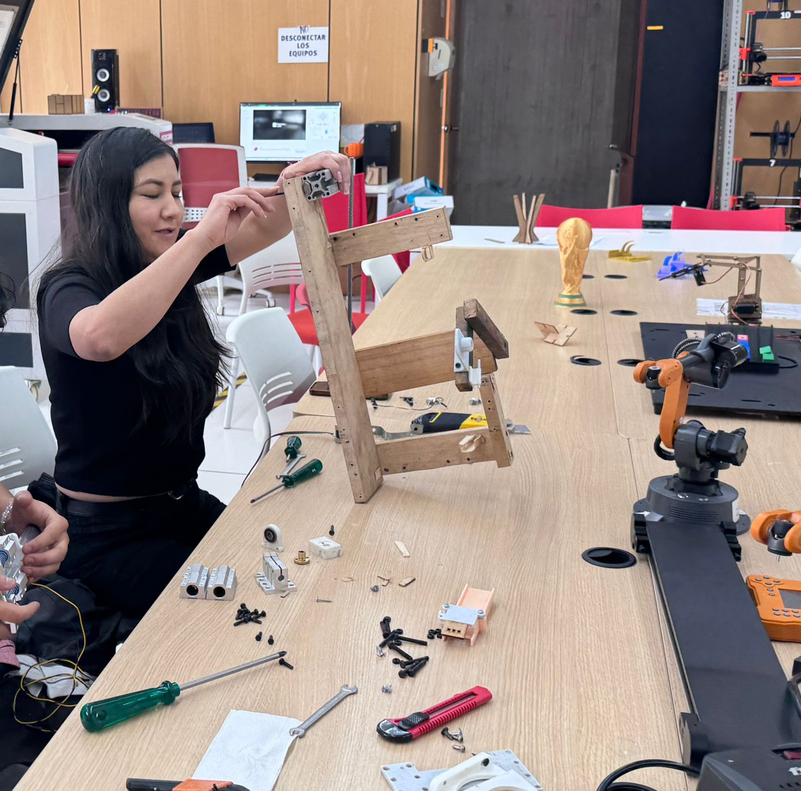
9. Finishing and Frame Validation
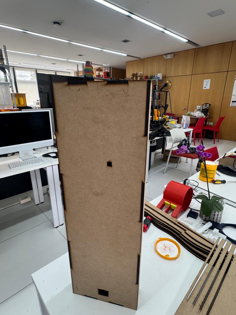
After assembly, the frame was reviewed from the front, side, and back. The visible organic slices created the intended layered effect, while the rear flat panel provided a stable surface for wall mounting and for future integration with the irrigation and electronics system.
The finishing process focused on cleaning the cut edges, removing loose MDF dust, and checking the burned zones left by the laser. The darker edges were kept because they clearly highlight the sliced construction method and increase the contrast between the organic curves and the flat structural plates.
The final frame was able to stand vertically and maintain the press-fit joints without additional fasteners in the first test. This confirmed that the digital fabrication workflow, from Fusion 360 to Slicer and DXF cutting, produced a physical structure that matched the intended dimensions and assembly logic.
Results of the fabrication stage
- The organic profile was preserved after cutting and assembly.
- The serial pieces created a layered visual texture that matches the design intention.
- The press-fit joints were functional with 5.5 mm MDF.
- The back panel provided stability for vertical positioning.
- The laser-burned edges worked as a visual finish and helped define the contour of each slice.
Files
The source fabrication files used for this stage are available below:
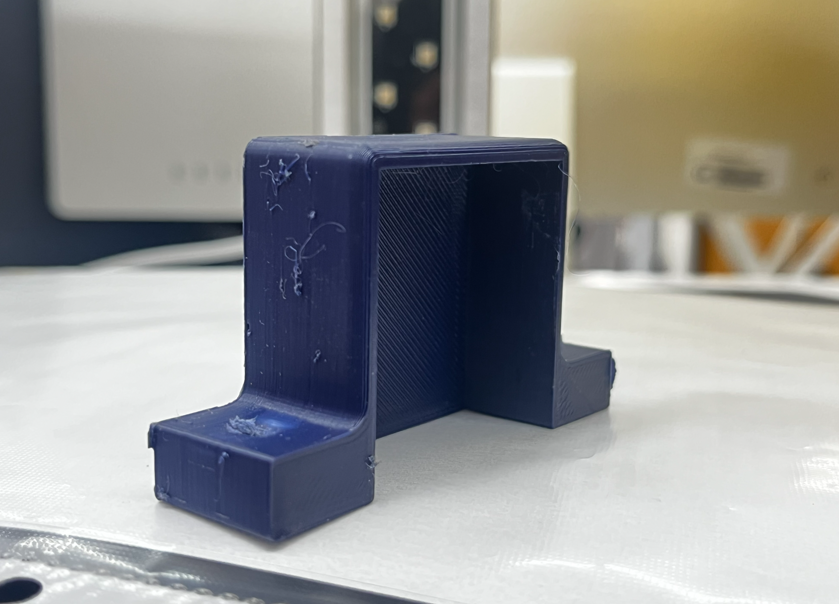
12. Water Pot, Orchid Planter Elements & Wiring Case Development
This stage focused on the design and fabrication of the 3D printed components that complement the wall frame: the water pot, the orchid planter elements, and a protective case for the wiring used during the Week System Integration stage. These parts were designed to connect the biological part of the project with the technical system, keeping the orchid support, irrigation, and cable management organized inside the OrquiWall Smart System.
The workflow combined Fusion 360 for CAD modeling, Ultimaker Cura for slicing, and FDM 3D printing using FLSUN and Prusa MK3+ printers. The selected material was PLA, because it is easy to print, dimensionally stable for prototypes, and suitable for validating the shape, fit, and assembly logic of the pot and case components.
CAD Software
Fusion 360 was used to model the pot, orchid support components, and wiring case.
Slicer
Ultimaker Cura was used to prepare the prints, generate supports, and export the G-code.
Printers
The parts were fabricated on FLSUN and Prusa MK3+ FDM printers.
Material
PLA filament was used for the printed prototypes and integration tests.
1. Design Intent
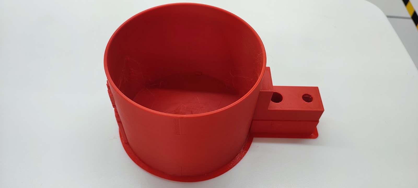
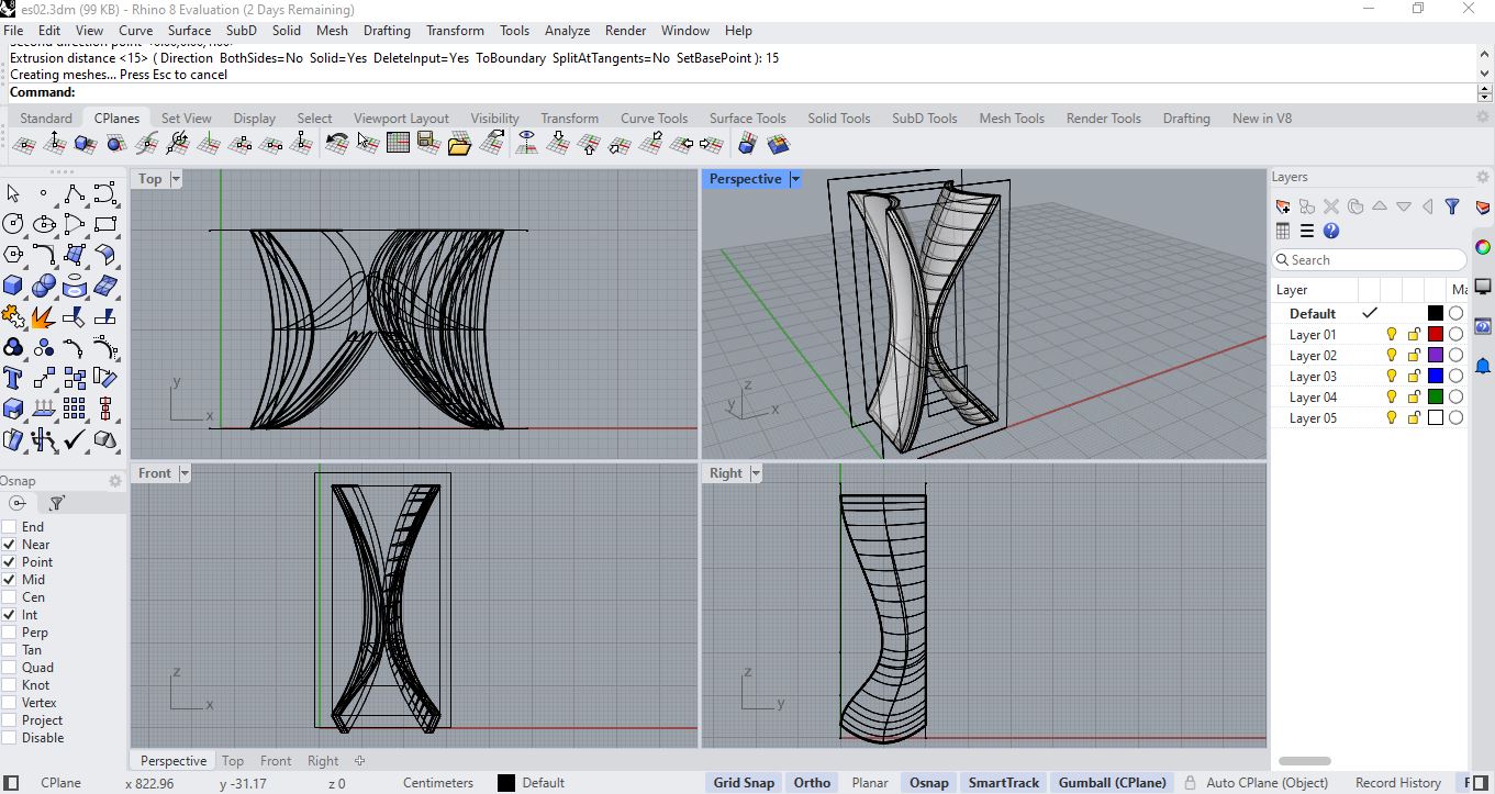
The water pot was designed as a functional container attached to the system, with a circular body and an integrated side extension. This side extension works as a connection area where the pot can interface with the frame, tubing, sensors, or mounting points. The geometry keeps a simple cylindrical volume for water storage while adding controlled openings for the irrigation system.
The orchid planter elements were developed to support the plant inside the wall system without hiding the organic language of the project. The parts had to be light, printable, and easy to remove during maintenance. The wiring case was designed as a separated enclosure to protect and organize the cable connections from the system integration stage, reducing exposed wiring and making the final assembly cleaner.
2. Modeling in Fusion 360
The components were modeled in Fusion 360 using a solid modeling workflow. The pot started from a cylindrical volume, then the wall thickness, base flange, and side connector were defined. The side connector was modeled with circular openings to allow future integration with water tubes, fastening elements, or system routing.
For the planter and wiring pieces, the CAD process prioritized practical assembly. Openings, flat bases, and accessible connection points were included to make the parts easy to print and easy to install on the frame. The wiring case was designed as a protective box for the electronics cable path, keeping the cables grouped and separated from the plant and water area.
- Water pot: cylindrical container with side connection block and base flange.
- Orchid planter elements: support pieces for holding or guiding the plant inside the wall system.
- Wiring case: protective enclosure for cables used in the Week System Integration setup.
- Design requirement: all parts had to be printable, removable, and compatible with the wall frame assembly.
3. Slicing in Ultimaker Cura
After modeling, the parts were exported from Fusion 360 and imported into Ultimaker Cura. Cura was used to orient the parts on the build plate, define the print quality, generate infill, and check if supports were required. The pot was oriented with the circular base on the bed to improve stability during printing and to keep the container walls continuous.
For the pot and case pieces, the slicing strategy balanced surface quality and print time. The side connector and holes required attention because they create bridges and internal edges. The planter elements were checked for bed adhesion, especially when printing narrow or curved details.
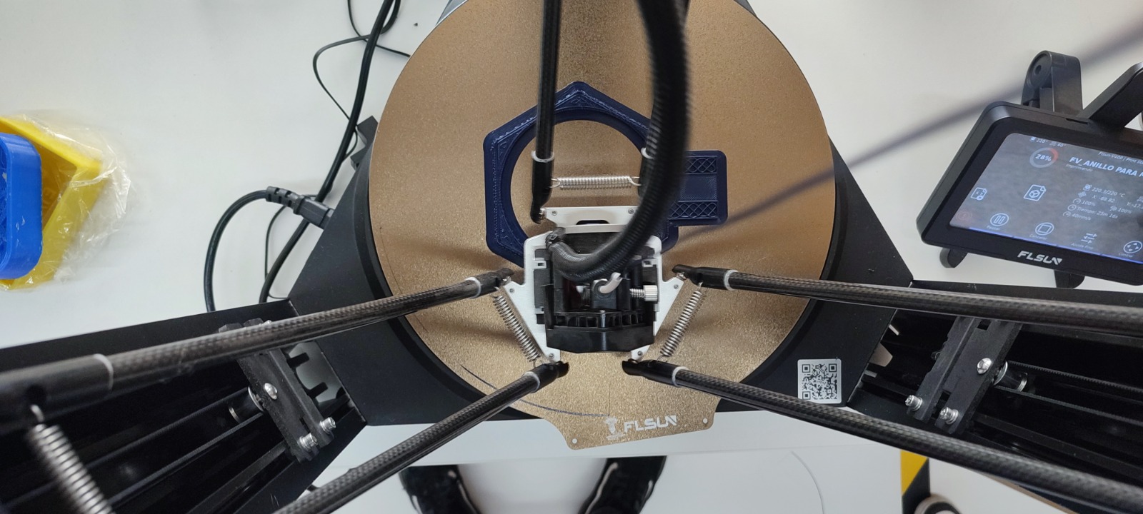
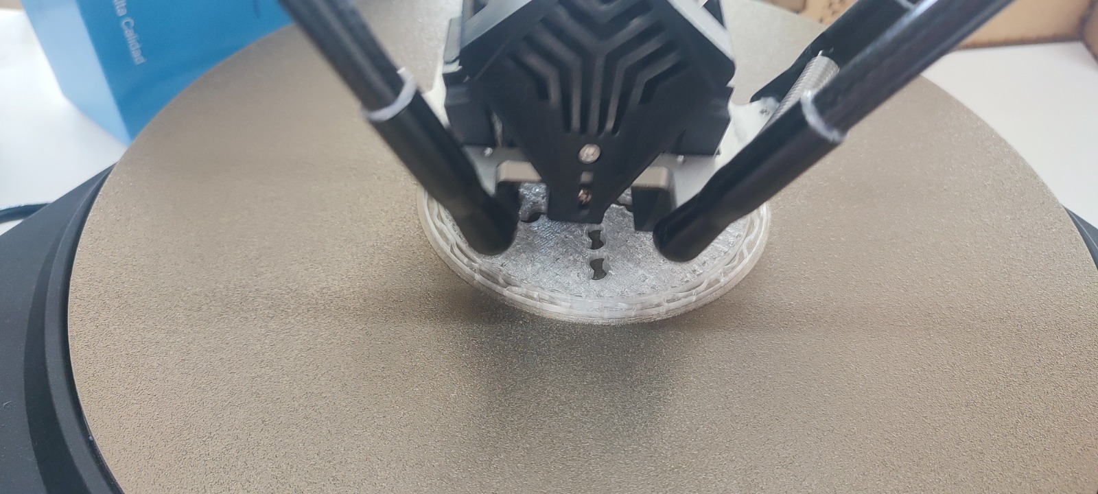
4. 3D Printing Process
The parts were fabricated using FDM printing. The FLSUN printer was used for the larger circular pot because its delta configuration and round build plate were suitable for the cylindrical geometry. The Prusa MK3+ was also used for complementary components and validation prints, especially for smaller elements where dimensional control and repeatability were important.
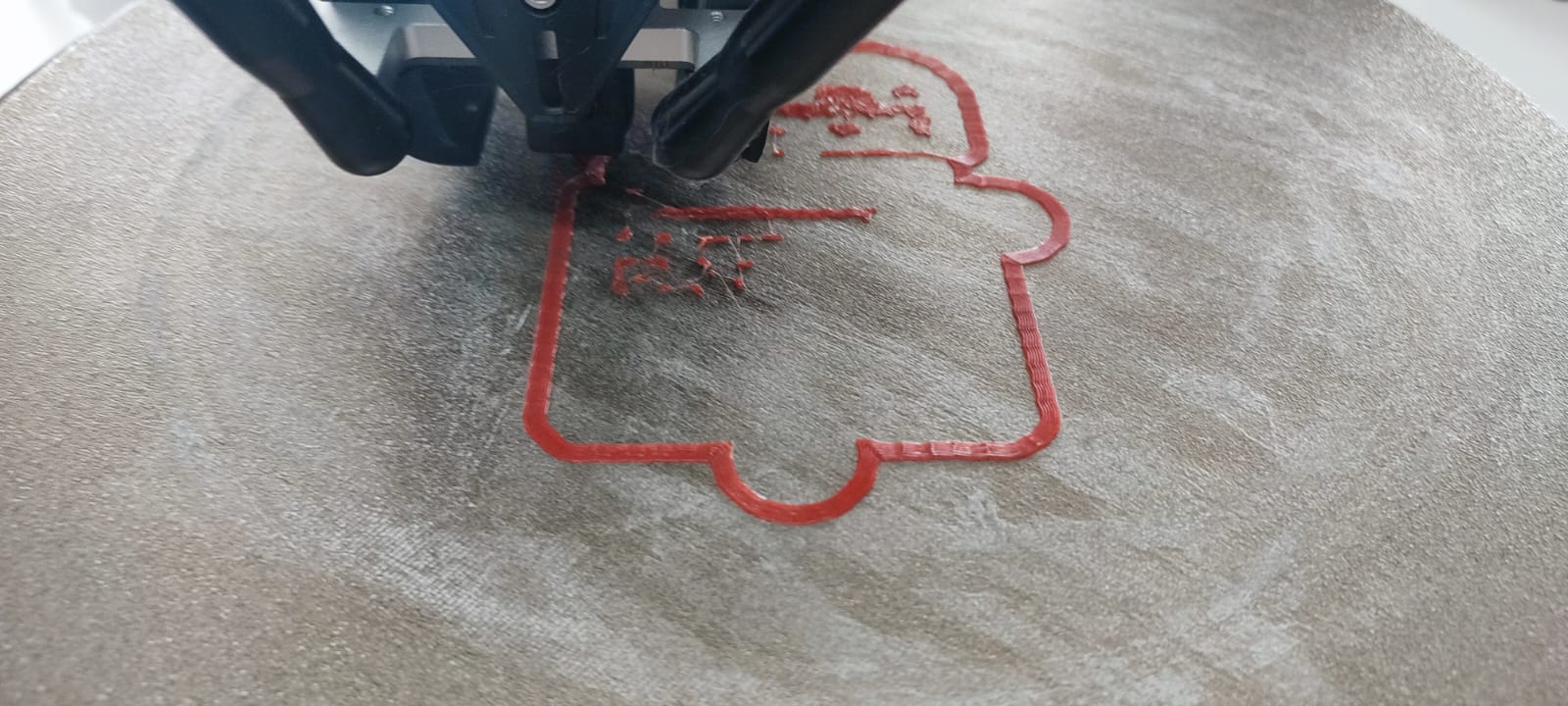
PLA was selected for the prototypes because it allowed fast iteration and clean surface definition. During printing, the first layers were monitored to verify adhesion and to avoid deformation at the base. The circular pot required stable adhesion around the perimeter, while the side connection block needed clean top layers and accurate holes.
Printing checks
- Bed preparation: clean the build plate and verify that the nozzle height supports proper first-layer adhesion.
- Part orientation: place the pot with the base on the bed to reduce the need for support inside the container.
- Layer monitoring: check the first layers and the perimeter of the circular wall.
- Opening quality: inspect the side connector holes after printing to confirm that tubing or fasteners can pass through.
- Fit verification: compare the printed pot and case with the MDF frame and the electronics/wiring layout.
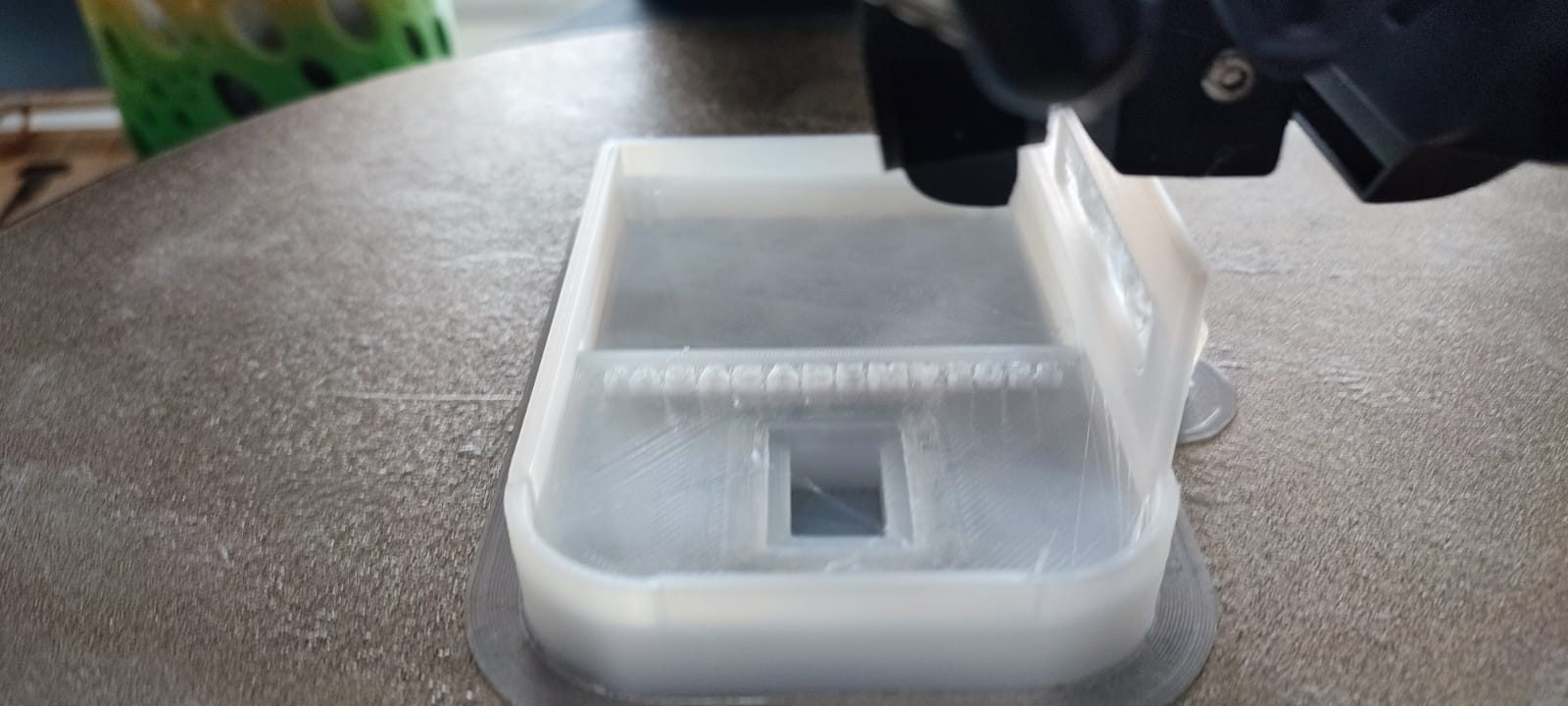
5. Wiring Case for System Integration
In addition to the pot and planter pieces, a case was fabricated for the wiring used in the Week System Integration stage. This case helps separate the electrical connections from the water and plant area, improving organization and reducing the risk of accidental cable movement during testing.
The case was designed as a practical enclosure rather than a decorative piece. Its role is to hold cables, protect connection points, and make the system easier to assemble and inspect. This is especially important because the final project combines irrigation, sensing, and structural elements in the same wall-mounted object.
For the integration week, the system required a small enclosure where the wiring could enter, bend, and remain protected while the sensors and actuators were connected. The case was designed with rounded corners to avoid sharp edges, an internal channel for cable organization, and openings that allow wires to pass through without being compressed.

Week System Integration function
- Cable protection: the enclosure keeps jumper wires and sensor cables grouped instead of exposed.
- System order: the internal space separates the wiring path from the water pot and orchid area.
- Maintenance: the case allows the cable route to be inspected and adjusted during testing.
- Mounting logic: small holes and openings were considered for fastening and cable entry/exit.
- Fabrication: the case was printed in PLA as a fast prototype for validating fit and cable routing.
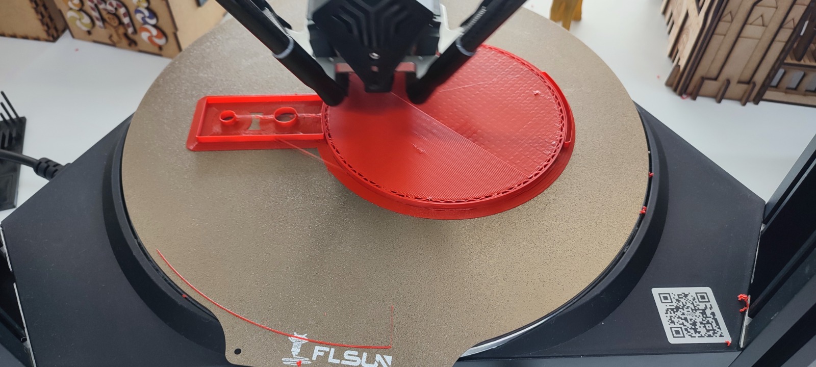
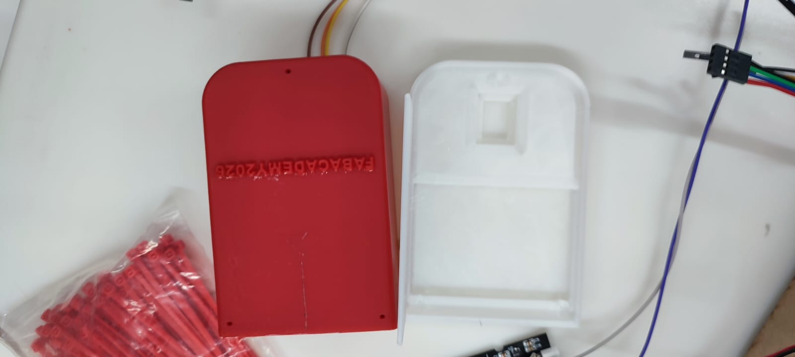
Two color/material tests were documented: a red PLA version and a white/translucent PLA version. The red print was useful for checking the outline and first-layer adhesion, while the white version made the internal geometry easier to see. After printing, the case was compared with the actual wiring to verify that the cable path had enough space and that the enclosure could support the system integration stage without interfering with other components.
6. Motor System Support Components
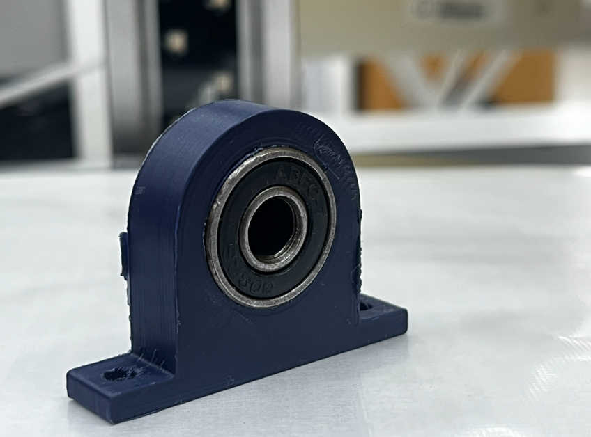
Additional PLA components were fabricated to support the mechanical/motorized subsystem of the project. These pieces were designed as structural holders for shafts, bearings, or guided moving elements. Their function is to keep the moving parts aligned, reduce unwanted vibration, and provide fixed mounting points inside the system.
The supports were modeled with thick bases, rounded transitions, and mounting holes for screws. One of the pieces works as a bearing holder: the circular cavity allows a bearing to be inserted and keeps the rotational axis centered. Other pieces use a U-shaped geometry to hold linear or vertical components while leaving enough clearance for movement and assembly.
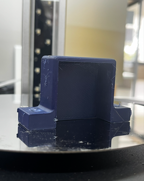
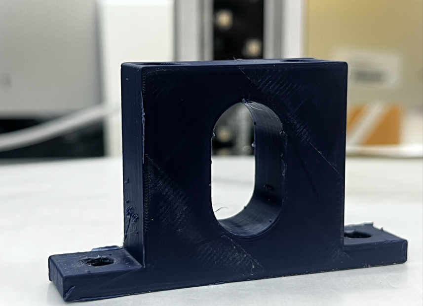
Design and fabrication criteria
- Material: PLA, printed by FDM for rapid iteration and dimensional testing.
- Mechanical role: support, align, and stabilize motorized or rotating components.
- Mounting strategy: screw holes were integrated into the base to fix the parts to the structure.
- Print orientation: the flat base was placed on the bed to improve adhesion and strength at the mounting area.
- Validation: bearing and shaft openings were checked after printing to verify fit and movement clearance.
These supports are small but important elements because they connect the digital design with the physical reliability of the mechanism. If the shaft, bearing, or guided component is not aligned, the motor system can lose efficiency or generate friction. For that reason, the printed parts were inspected for hole quality, base flatness, and overall rigidity before being integrated into the system.
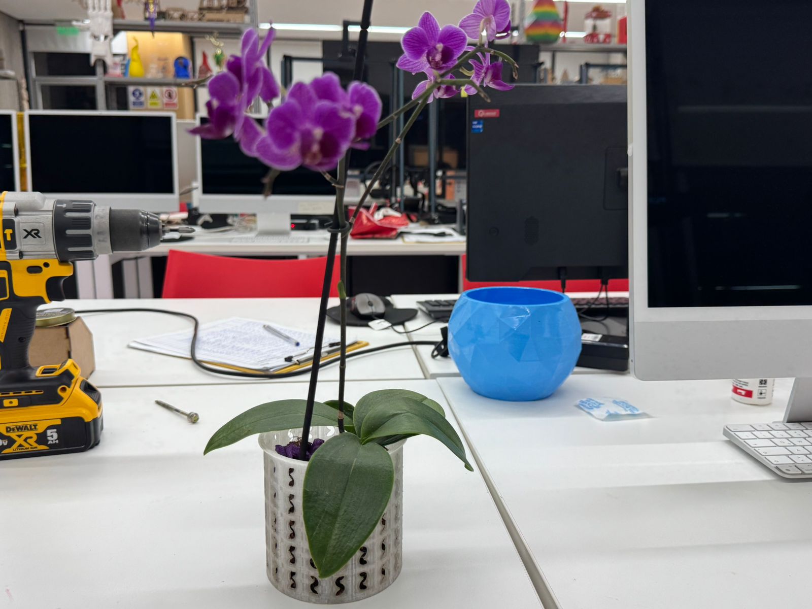
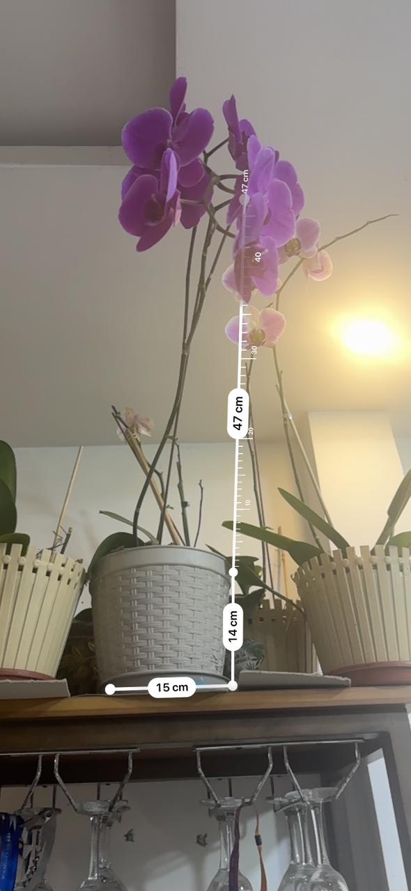
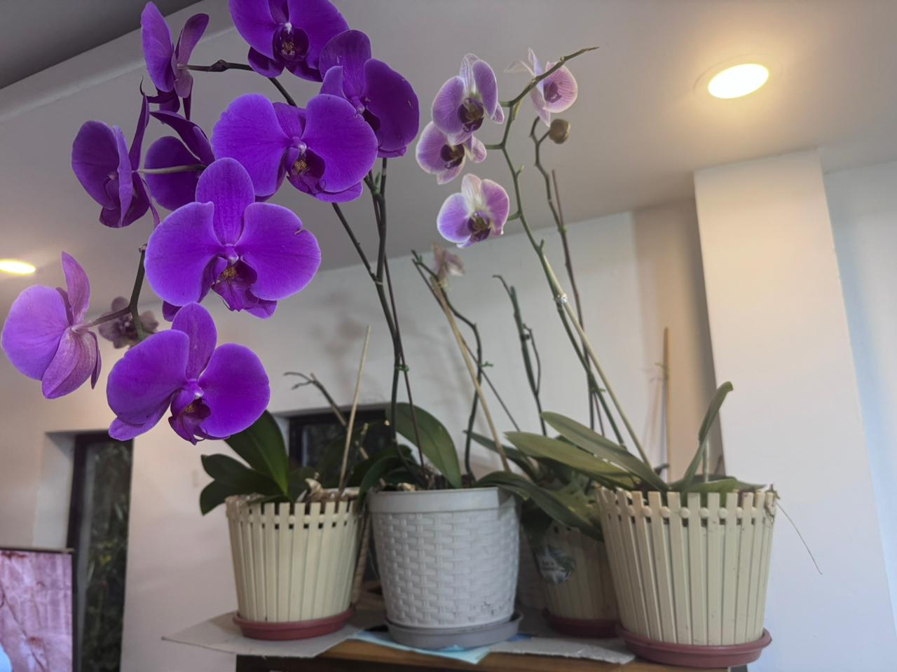
7. Orchid Pot Verification and Presentation
After fabricating the pot and the complementary printed components, the next step was to verify the real interaction between the orchid and the container. This validation was not only dimensional; it also evaluated presentation, plant stability, access for maintenance, and how the printed part communicates the final intention of the OrquiWall Smart System.
The orchid was placed inside the printed pot to check the relationship between the plant, the container diameter, and the vertical height of the stems. The test confirmed that the pot can visually frame the orchid without hiding the leaves or flowers. The perforated wall also supports the idea of an orchid container that allows air exchange around the roots, which is important for this type of plant.
Verification criteria
- Scale: the pot size was checked against the real orchid leaves, roots, and flower stems.
- Stability: the plant remained upright without the container visually overpowering the orchid.
- Visibility: the flowers and leaves stayed visible, supporting the ornamental purpose of the wall system.
- Ventilation: the side openings suggest better air circulation for the orchid root area.
- Integration: the pot can be coordinated with the wall frame, water system, and cable management components.
This presentation test helped validate the transition from a digital and printed component to a real plant support element. The result shows that the pot is not only a technical container for the irrigation system, but also a visible part of the project identity: it holds the orchid, protects its position, and reinforces the relationship between digital fabrication and biophilic design.
Results
- The printed pot was suitable for presenting the orchid at prototype scale.
- The plant remained visually centered and readable inside the container.
- The perforated design supports the biological needs of the orchid more clearly than a closed pot.
- The pot can continue into the next integration stage with irrigation and frame mounting tests.
- The wiring case and motor supports remain part of the technical layer, while the pot becomes the visible biological interface.
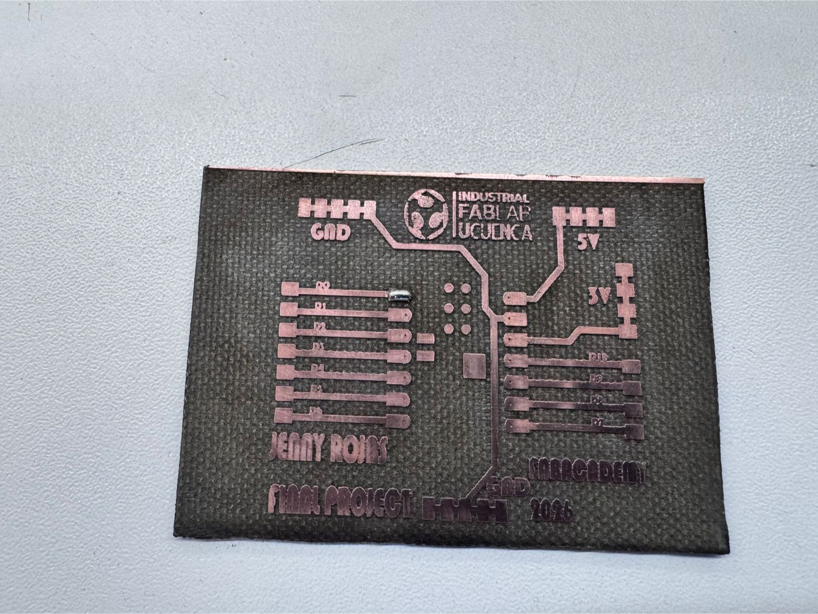
13. Electronic Production: PCB Design, Fabrication & System Electronics
The electronic production stage defines the control board for the OrquiWall Smart System. The goal was to design and fabricate a custom PCB capable of connecting the microcontroller, motor driver, sensors, display, and limit switches required for the irrigation and movement system.
The board was designed in KiCad. The process started with the schematic, where the electrical relationships between the ESP32 XIAO C3, A4988 driver, stepper motor, humidity sensor, LCD display, and limit switches were defined. After validating the schematic logic, the PCB layout was developed and exported for fabrication.
Design Software
KiCad was used for schematic capture, PCB routing, and board visualization.
Controller
ESP32 XIAO C3, selected as the central microcontroller for sensing and actuation.
Fabrication
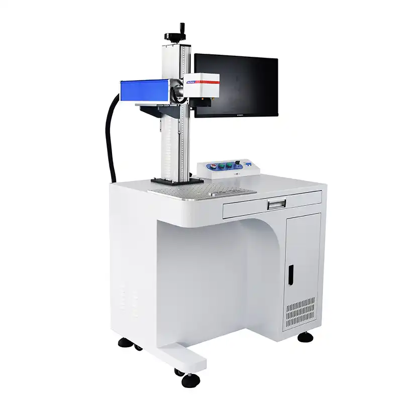
The PCB was produced using a fiber laser machine to engrave the copper traces.
System Role
The board integrates the motor, sensor, display, and limit-switch wiring into one control layer.
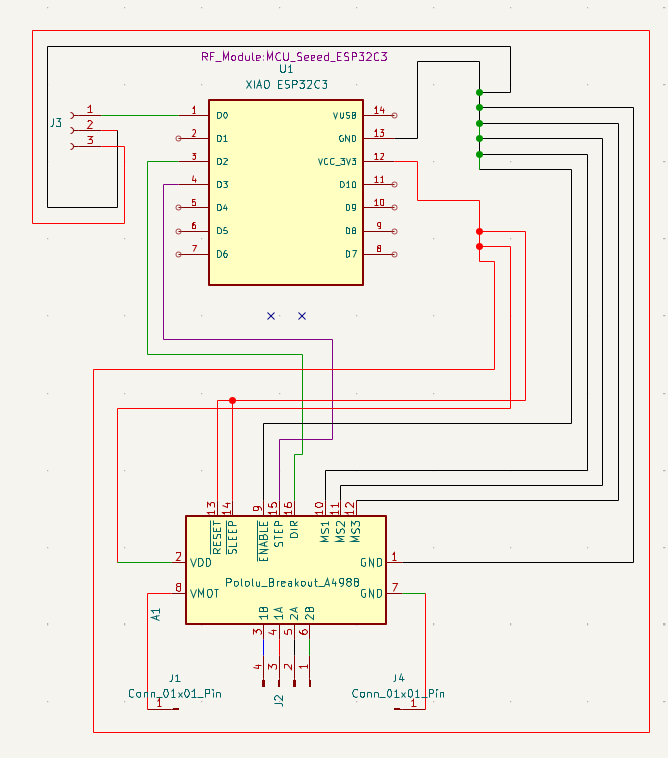
1. Schematic Design in KiCad
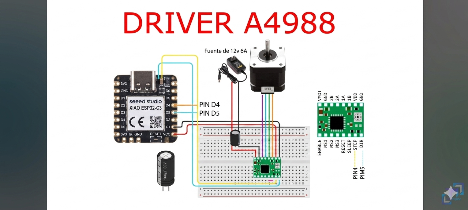
The schematic stage was used to organize the electronic logic of the system before moving into physical routing. Each module was represented as part of the circuit: the ESP32 XIAO C3 as the controller, the A4988 as the stepper motor driver, the humidity sensor as the environmental input, the LCD as the user feedback interface, and the two limit switches as safety and position references.
The stepper motor system required special attention because the A4988 driver needs independent motor power and control signals from the microcontroller. The schematic therefore separated logic connections from the motor power path. This makes the board easier to debug and helps prevent confusion between low-voltage control signals and the 12-15 V motor supply.

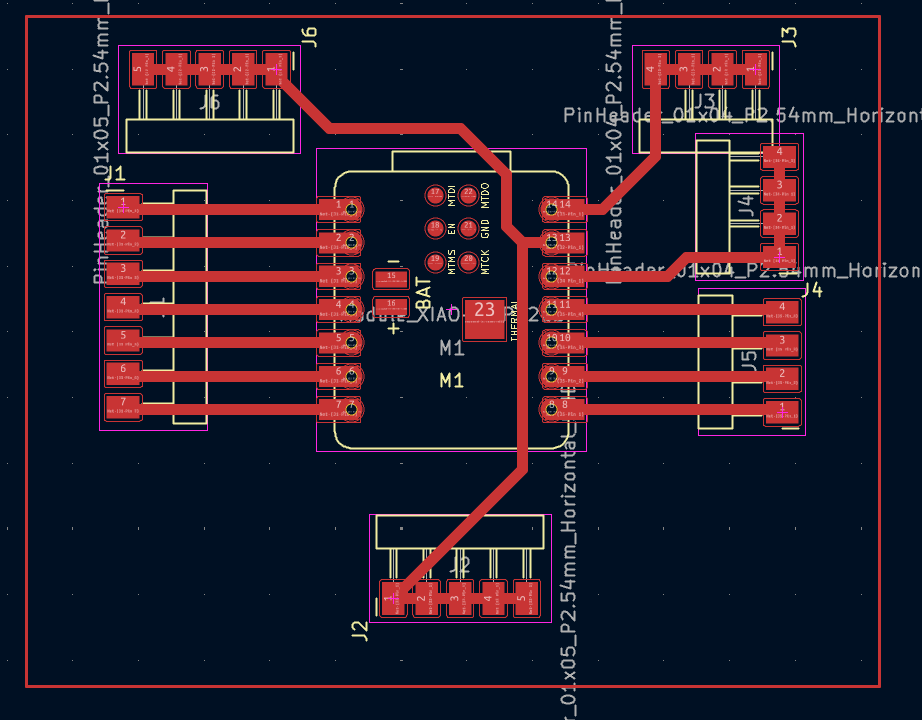
2. PCB Layout and Routing
After the schematic was completed, the components were placed in the PCB editor. The layout was organized to keep the microcontroller accessible, provide space for the A4988 driver, and route the motor, sensor, screen, and switch connections clearly. The board traces were designed to be readable and suitable for the selected fabrication method.
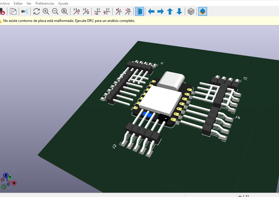
The PCB layout was checked before export to confirm that the traces were continuous, the pads were reachable for soldering, and the board could be fabricated using the fiber laser process. A 3D preview was also used to evaluate component placement and verify the board as a physical object before manufacturing.
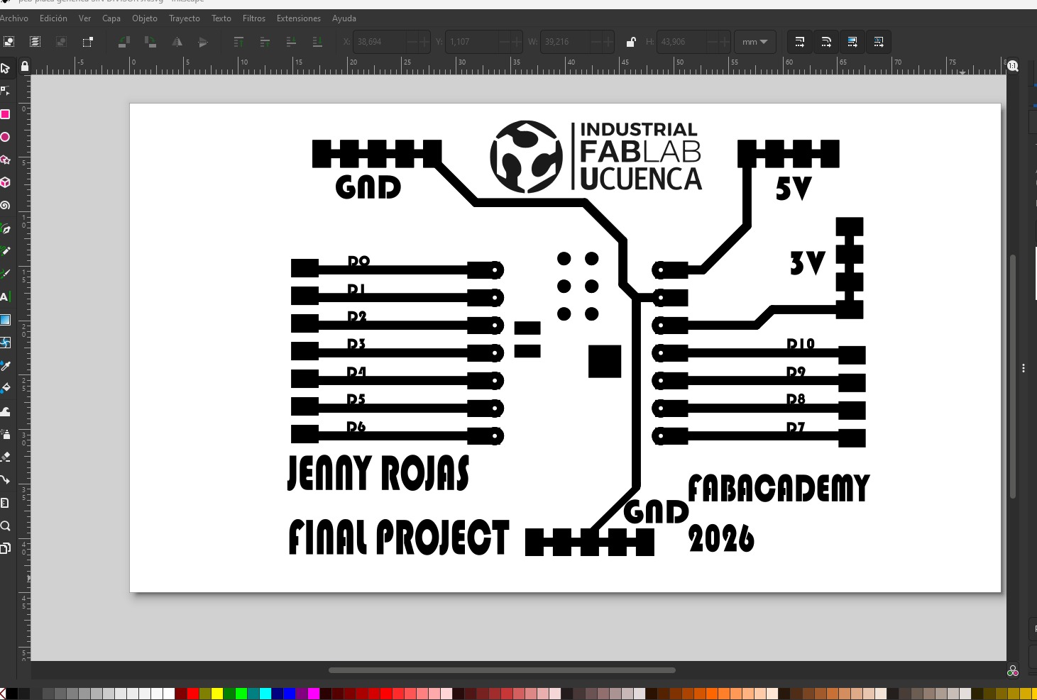
Before fabrication, the trace artwork was also reviewed as a black-and-white vector file. This step helped prepare the geometry for the fiber laser workflow, where clear contrast between copper-removal areas and conductive traces is essential. Labels such as GND, 5V, 3V, and digital pin references were added to make the board easier to identify during assembly and debugging.
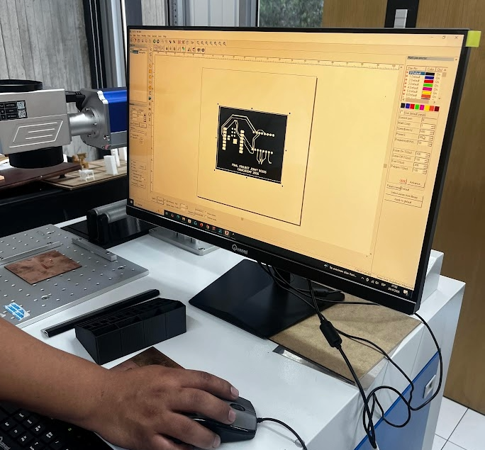
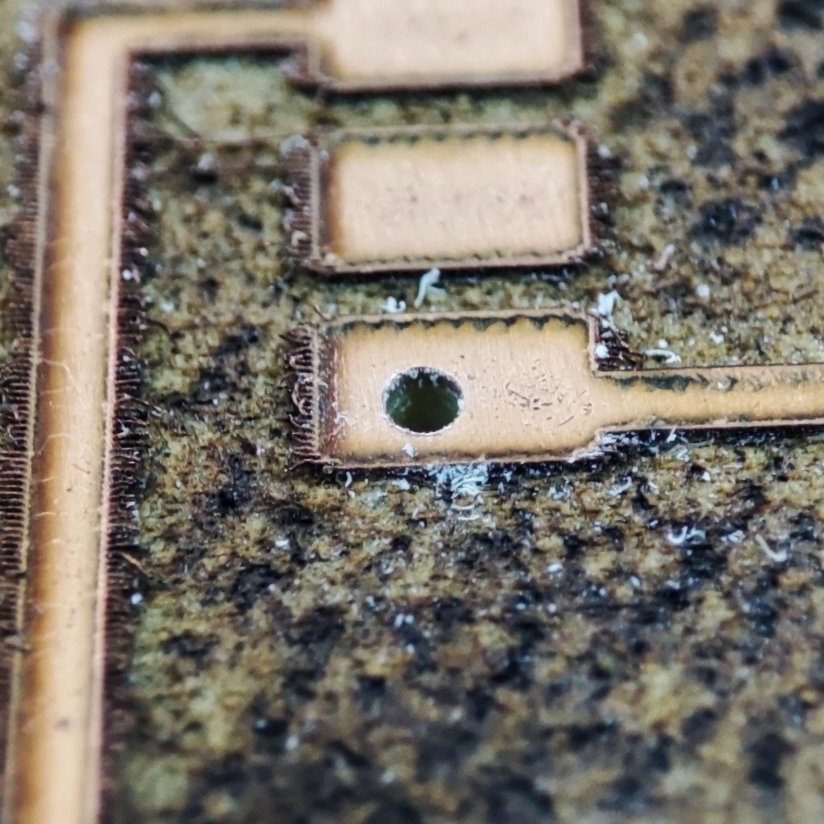
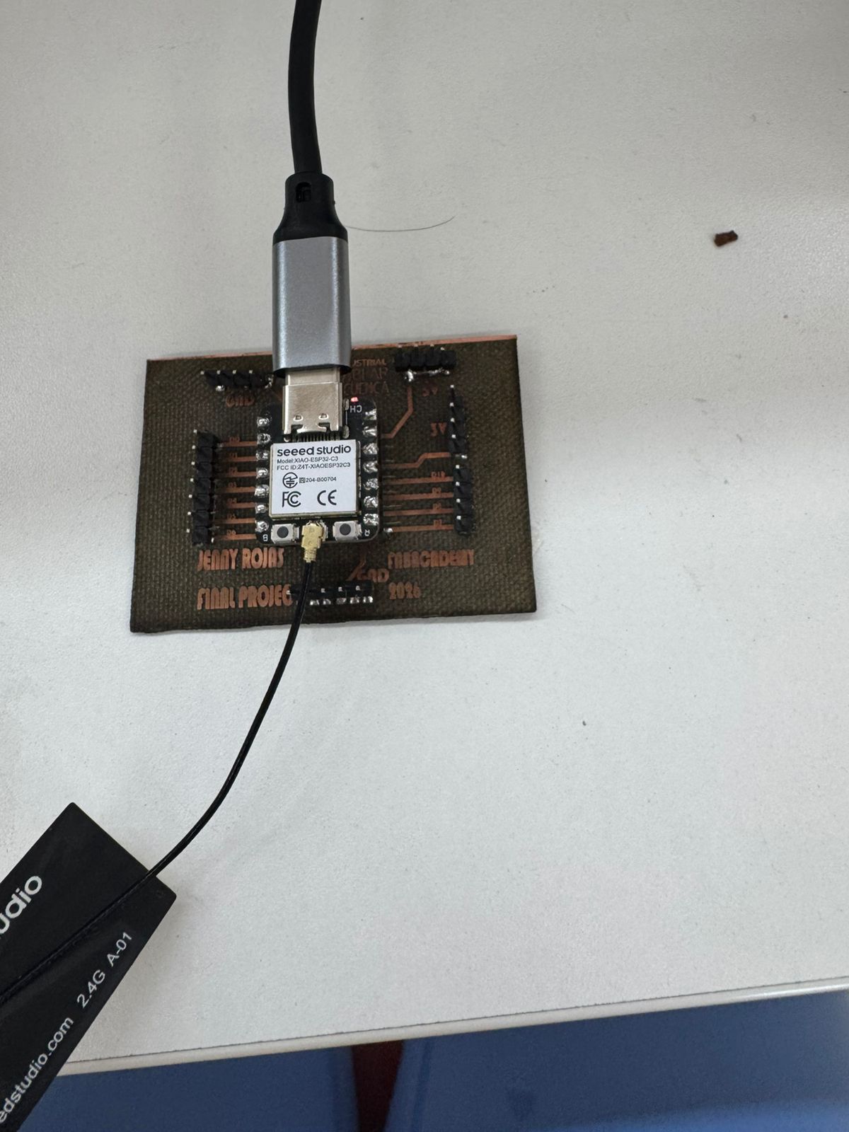
3. PCB Fabrication with Fiber Laser
The PCB was fabricated using a fiber laser machine. The copper board was prepared and placed in the machine bed, then the exported trace file was used to engrave the unwanted copper areas and leave the conductive paths required for the circuit. This process connects the electronic design stage with computer-controlled fabrication.
After laser engraving, the board was inspected to verify that the traces were separated correctly. The holes were drilled for the components and connectors, and the board was cleaned before soldering. This workflow allowed the PCB to be produced directly from the KiCad design files.
4. Bill of Materials
The complete project BOM with supplier references, published prices, Ecuador referential prices, and project subtotals is documented in Section 6. Bill of Materials (BOM).
| Component | Quantity | Function in the System |
|---|---|---|
| Custom PCB board | 1 | Main board for organizing and connecting the control electronics. |
| ESP32 XIAO C3 | 1 | Microcontroller for reading sensors and controlling outputs. |
| A4988 stepper motor driver | 1 | Driver used to control the stepper motor movement. |
| Stepper motor, 12-15 V | 1 | Actuator for the mechanical movement of the system. |
| 40 cm lead screw | 1 | Mechanical transmission element for linear movement. |
| Humidity sensor | 1 | Input sensor for monitoring moisture conditions. |
| LCD display | 1 | Visual interface for showing system information. |
| Limit switches | 2 | End-stop references for movement safety and positioning. |
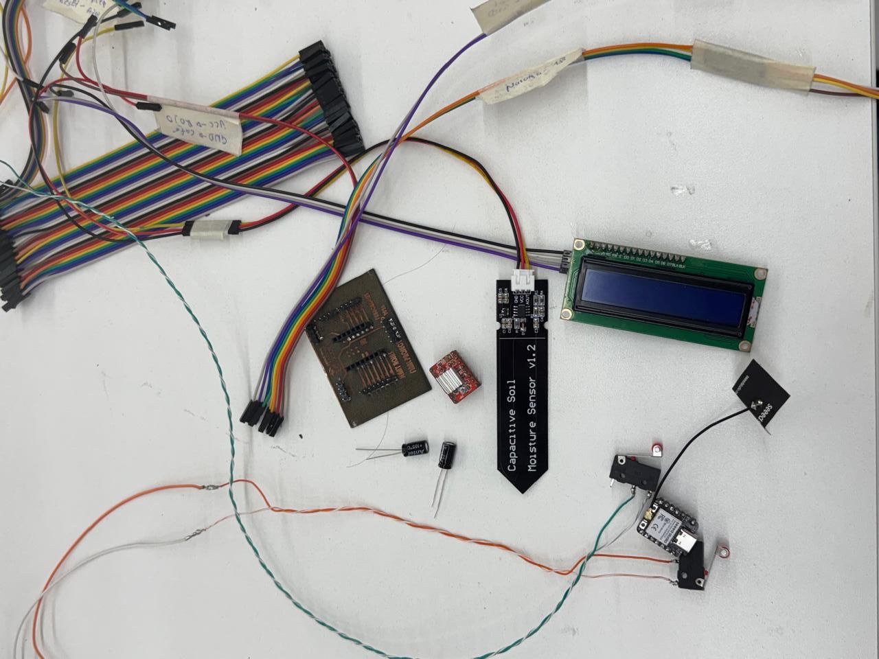
| Lead screw bearing | 1 | Mechanical support for stabilizing the screw rotation. |
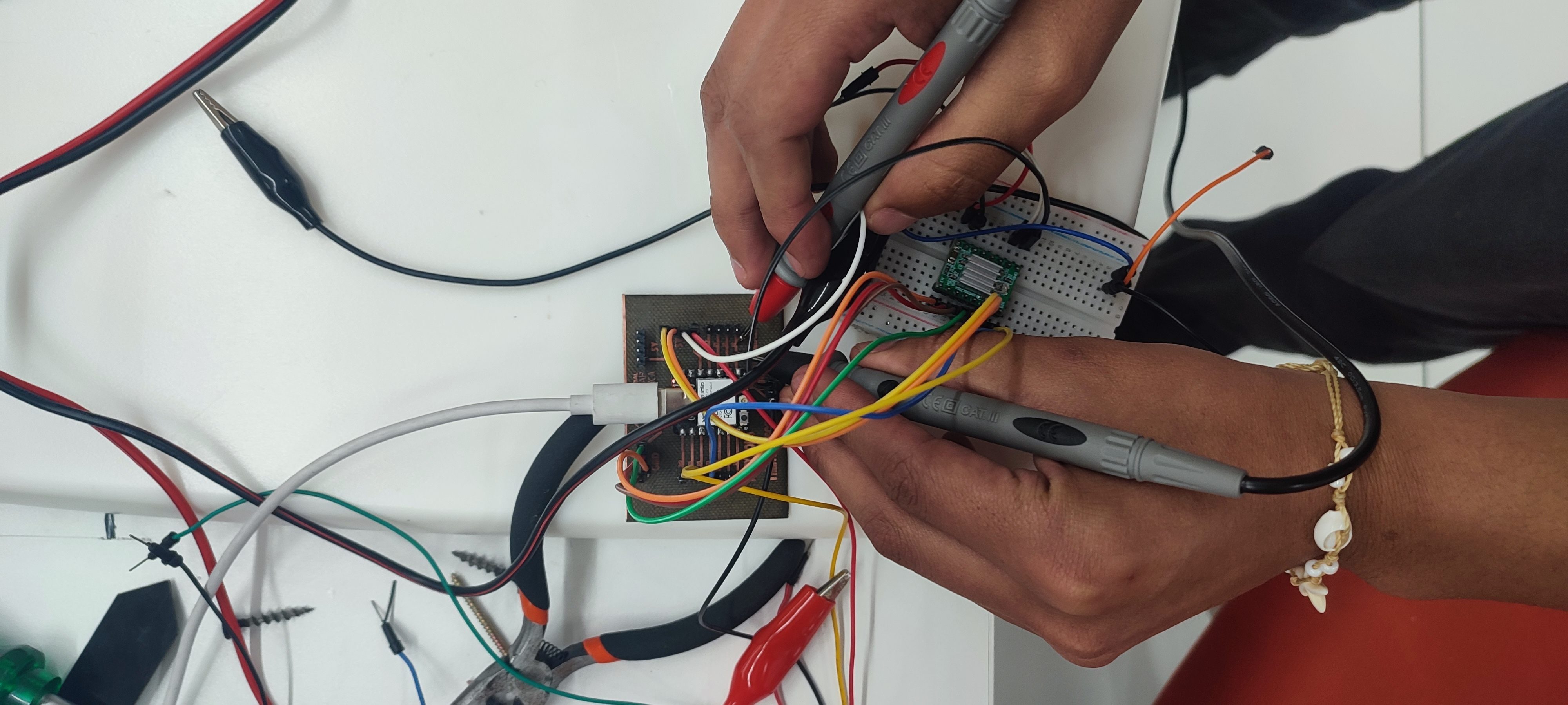
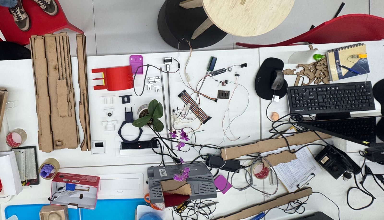
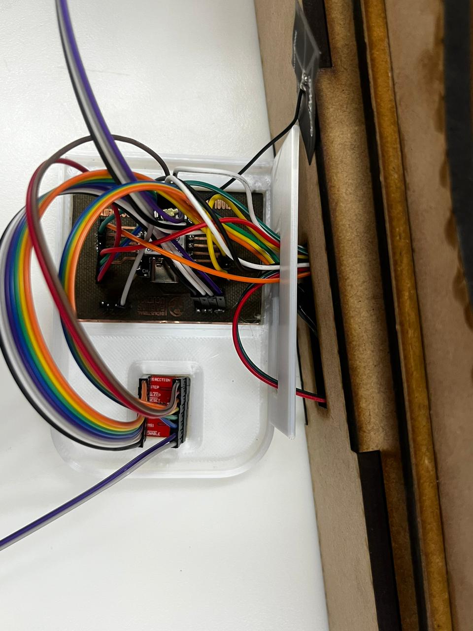
The components were organized physically on the table before final integration. This made it easier to identify each cable path, label connections, and verify that the LCD, humidity sensor, limit switches, ESP32 XIAO C3, and driver-related wiring matched the board logic. The wiring was intentionally labeled because the system includes multiple signal and power paths.
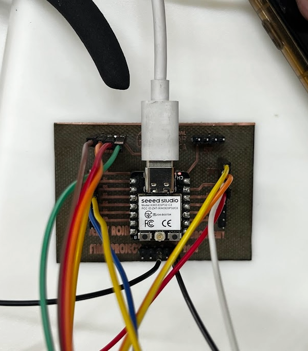
5. Soldering, Testing and Integration
Once the board was engraved and drilled, the electronic components and headers were soldered. The board was then checked with continuity tests to confirm that the traces were connected where expected and isolated where separation was required. This step was important before connecting the ESP32 XIAO C3 and the A4988 driver to avoid damaging components.
The A4988 driver was connected according to the motor control requirements. The stepper motor uses the 12-15 V supply, while the control signals come from the microcontroller. The humidity sensor, LCD display, and limit switches complete the interface between the biological, mechanical, and electronic layers of the OrquiWall Smart System.
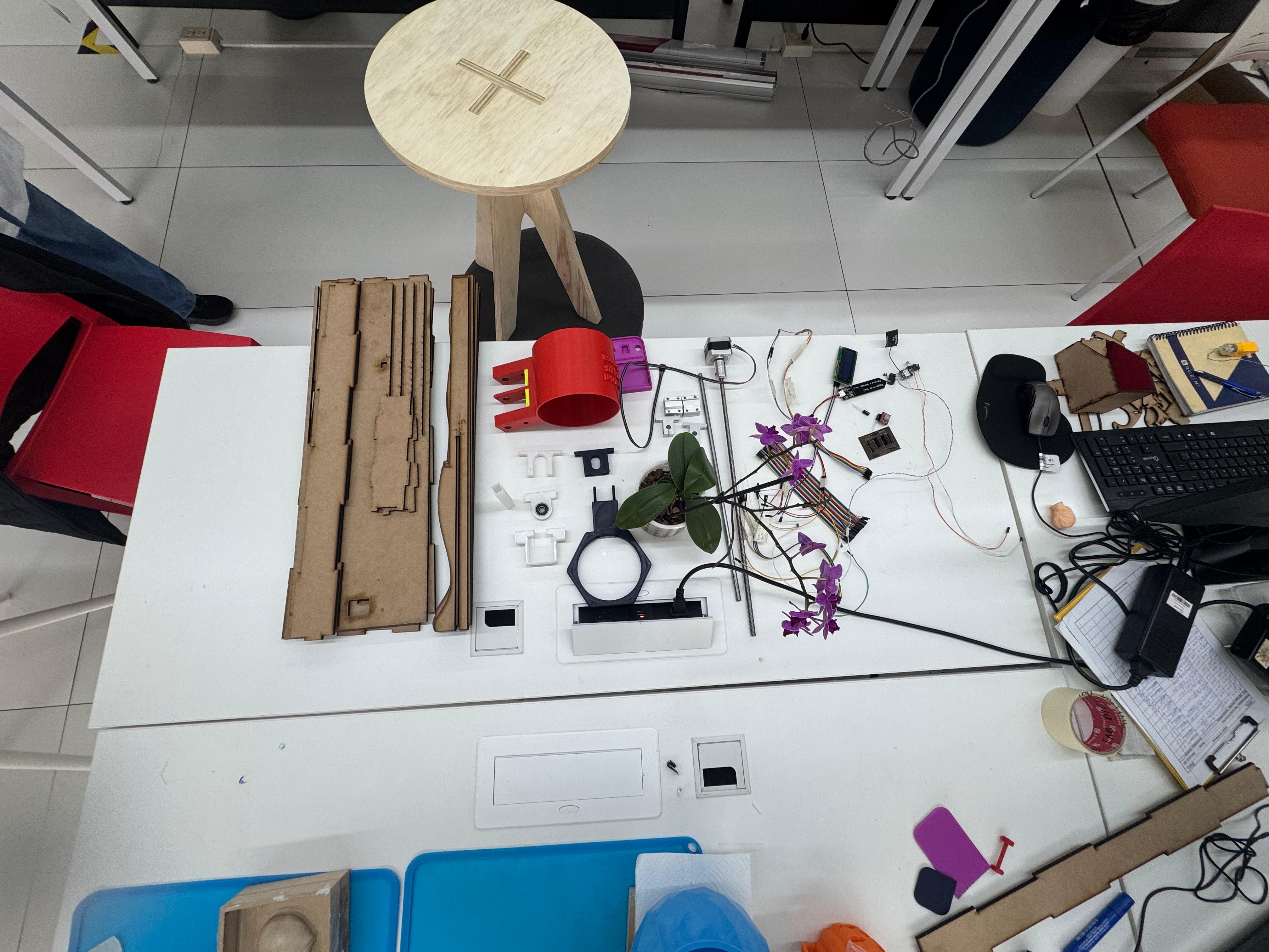
6. Full System Electronics Integration
After testing the board and individual components, the electronics were placed together with the mechanical and biological elements of the project. This integration table included the MDF wall frame, printed pot, motor supports, lead screw, orchid, LCD display, sensor wiring, PCB, cables, and power supply. Seeing all parts together helped verify that the electronic system was not isolated from the physical design, but connected to the final product architecture.
This stage was useful for checking cable length, component accessibility, and the spatial relationship between the electronics and the fabricated structure. The motor and lead screw components require stable alignment, while the humidity sensor and LCD need to remain reachable for testing. The wiring case documented in the previous section supports this stage by grouping cables and reducing disorder during assembly.
7. Downloadable Files
The PCB design and fabrication files are available below:
14. Final Component Assembly: Mechanical Design & System Integration
This stage documents the final component assembly of the OrquiWall Smart System, oriented to the Mechanical Design week. The objective was to bring together the electronic system, motorized mechanism, structural frame, water reservoir, orchid pot, and sensing components into one integrated prototype.
The assembly process was developed in stages. First, the electronics and sensors were tested separately. Then the stepper motor, lead screw, bearing, and printed supports were assembled as a mechanical movement module. After that, the structure and reservoir were positioned to verify clearances, stability, and interaction between the moving mechanism and the plant container.
Mechanical Goal
Validate movement, support alignment, and component placement for the final integrated prototype.
Actuation
Stepper motor with 40 cm lead screw, bearing support, and printed holders.
Inputs
Humidity sensor and limit switches used to verify control and movement references.
Final Interface
Water reservoir, orchid pot, and MDF structure were tested together as the visible system.
1. Electronic System and Sensor Test
The first step was to test the electronic system before installing it in the full structure. The controller, driver, sensor wiring, and breadboard connections were checked while the motorized mechanism was kept accessible on the table. This made debugging easier because every cable and signal could be inspected directly.
The motor was tested together with the sensor logic and limit references. This helped verify that the electronic layer could control movement before the mechanical parts were fixed permanently. At this point, the purpose was not aesthetic presentation, but functional validation: power, signal continuity, motor response, and sensor behavior.
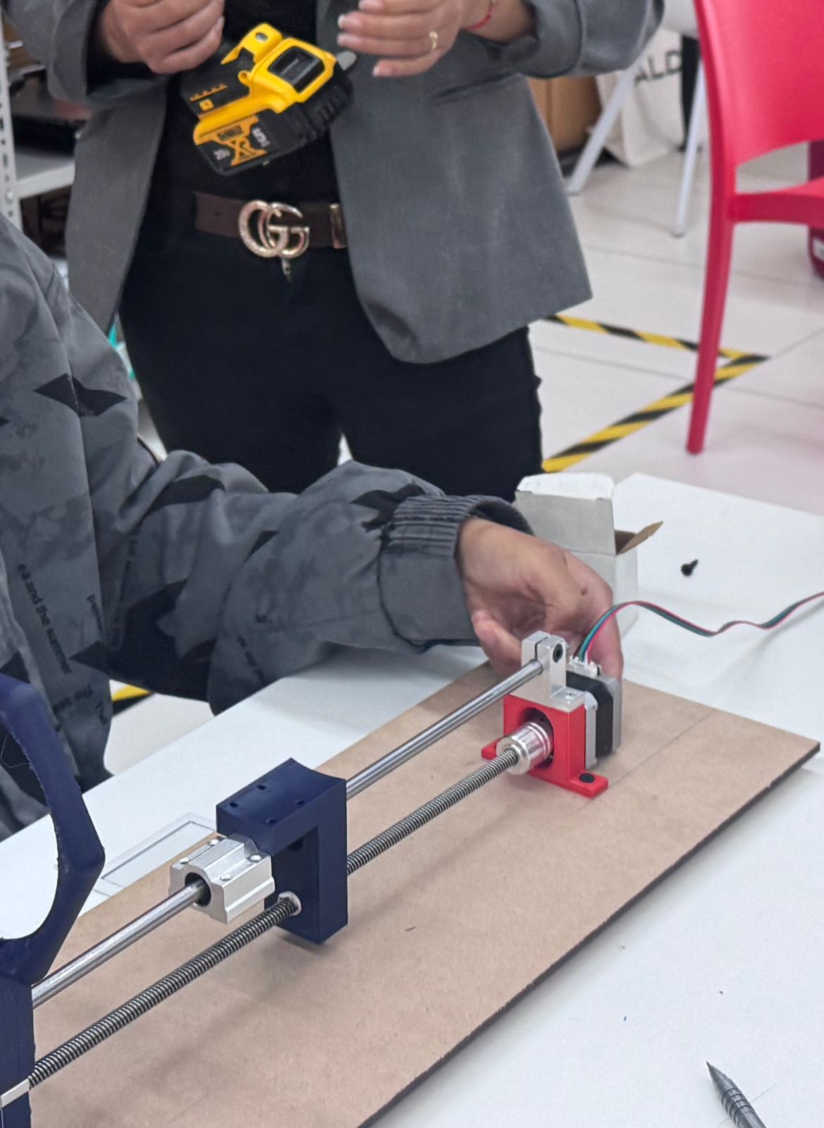
2. Motor, Lead Screw and Support Assembly
After validating the electronic behavior, the mechanical movement module was assembled. The stepper motor was connected to the lead screw, and the screw was aligned with guide rods and printed supports. The bearing support was used to stabilize the screw and reduce unwanted movement during rotation.
The support pieces were tested on a temporary MDF base to check alignment before being integrated into the final vertical structure. This step was important because even a small misalignment between the motor, lead screw, bearing, and guide rods can increase friction or block the movement.
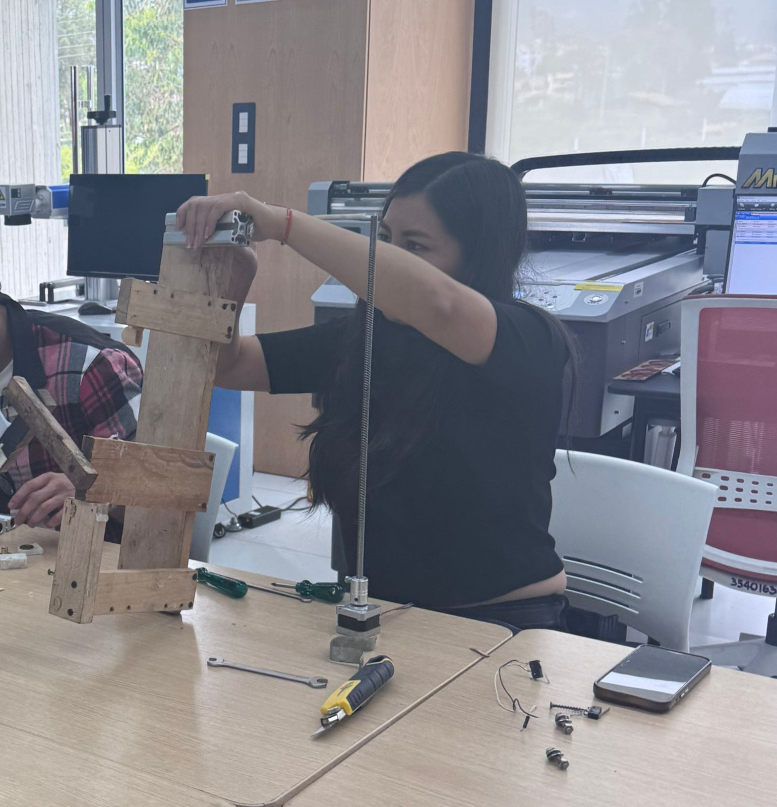
3. Structure Integration
Once the motor module worked independently, the next step was to connect it with the structure. The MDF support was used to hold the mechanism vertically and to simulate the final wall-mounted behavior. During this stage, the position of the screw, motor, bearing, and moving pot support was checked relative to the back panel.
The structural assembly had to satisfy two conditions: it had to be rigid enough to hold the moving reservoir/pot system, and it had to leave enough room for the electronics and cables. This is where the mechanical and electronic layers started to converge into a single prototype.
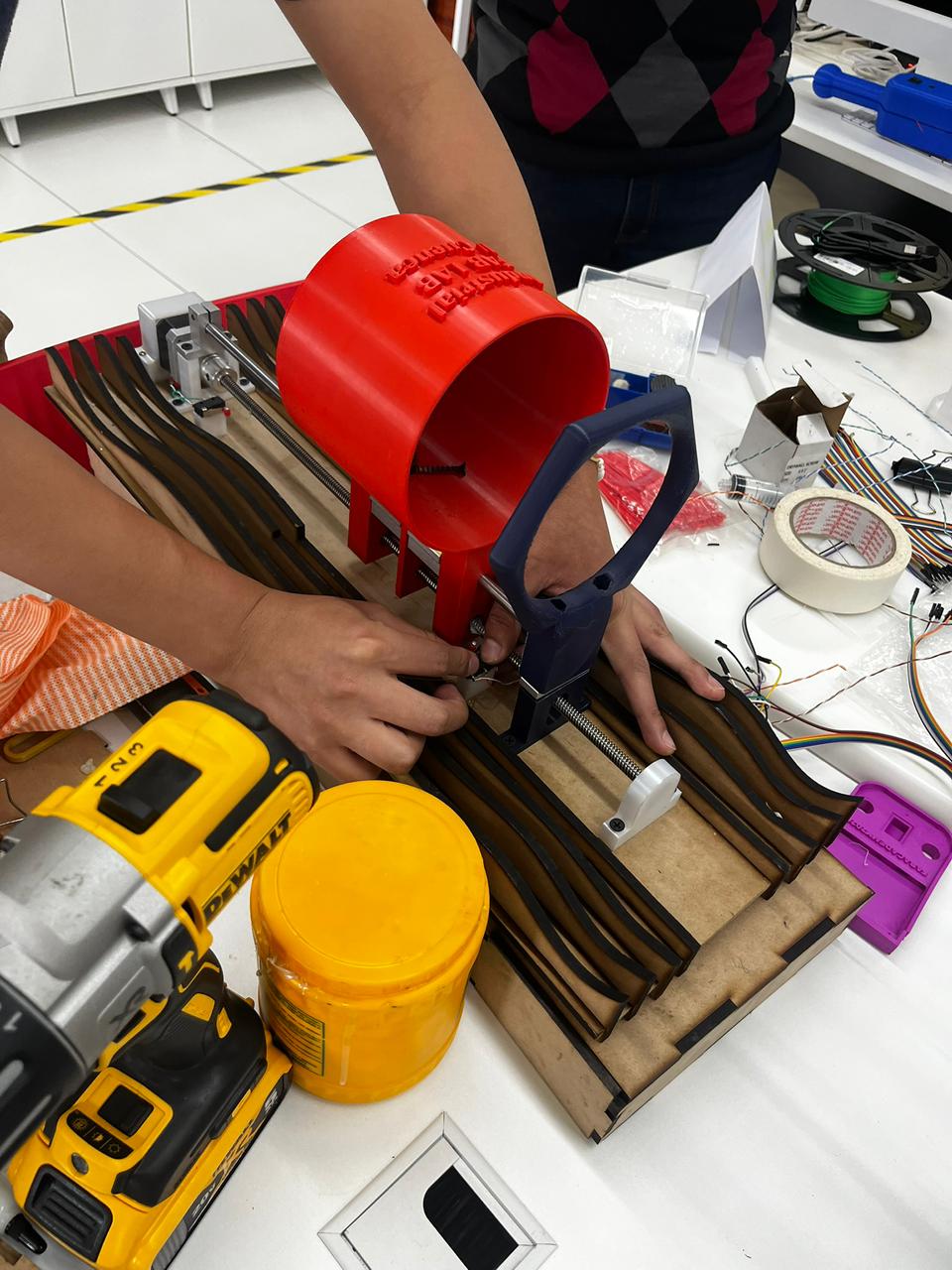
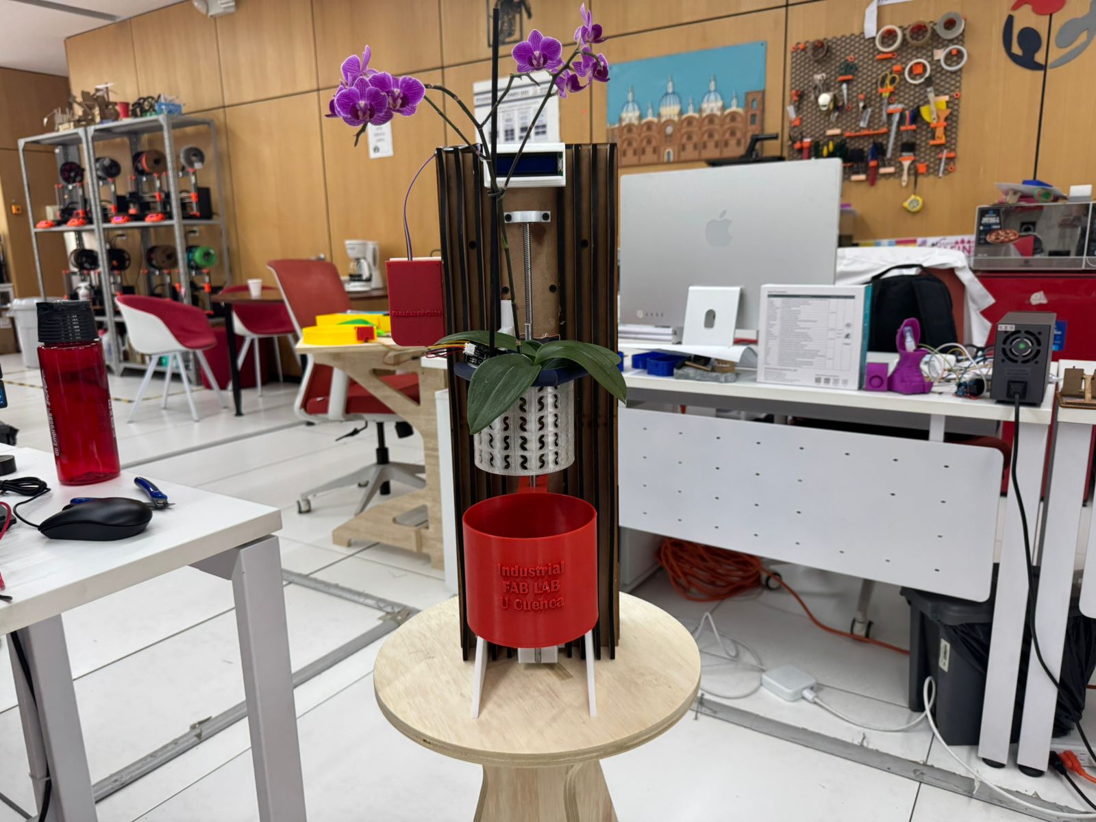
4. Slicer Framework for Aesthetic Integration
The sliced framework generated in Slicer was not only used as a structural base; it also became the main visual layer of the final prototype. The repeated MDF ribs create a rhythmic organic surface that contrasts with the technical components: the lead screw, the reservoir, the LCD screen, and the wiring.
During assembly, this framework was used to test how the fabricated aesthetic surface could support the functional elements without hiding them. The red reservoir was positioned over the ribbed structure, the motorized axis was aligned with the frame, and the LCD support was placed close to the sliced pattern to verify visibility and cable access.
Framework validation criteria
- Visual identity: the serial MDF ribs maintain the organic language defined in the digital model.
- Component support: the frame provides a base for the reservoir, LCD, motor supports, and cable routing.
- Accessibility: the sliced pattern leaves enough space to access screws, connectors, and moving parts.
- System readability: the mechanical and electronic parts remain visible as part of the final design.
- Integration: the framework connects the Computer-Controlled Cutting workflow with Mechanical Design and System Integration.
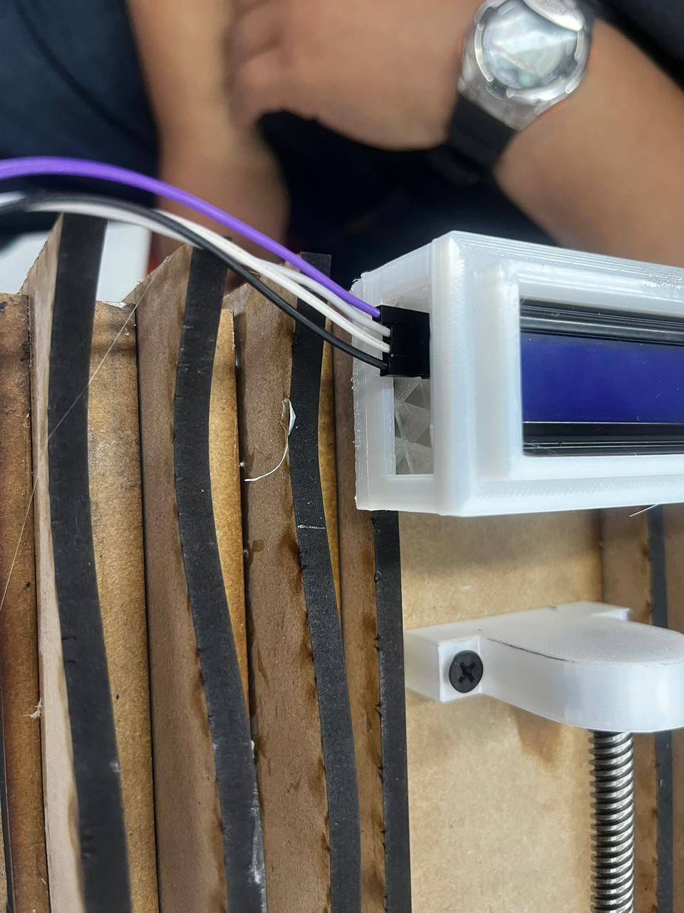
5. Electrical Wiring, Connection Tests and Final Routing
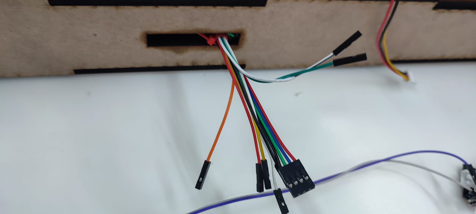
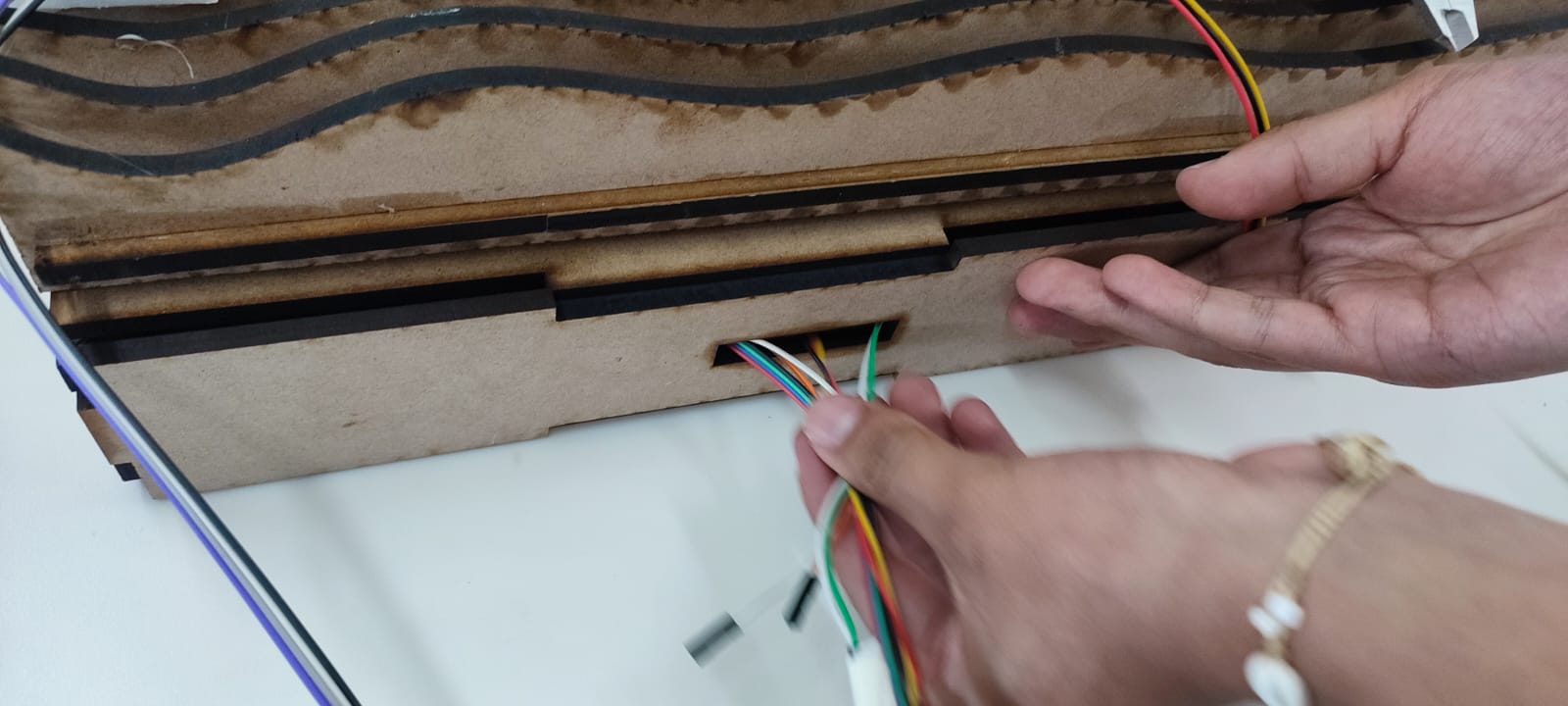
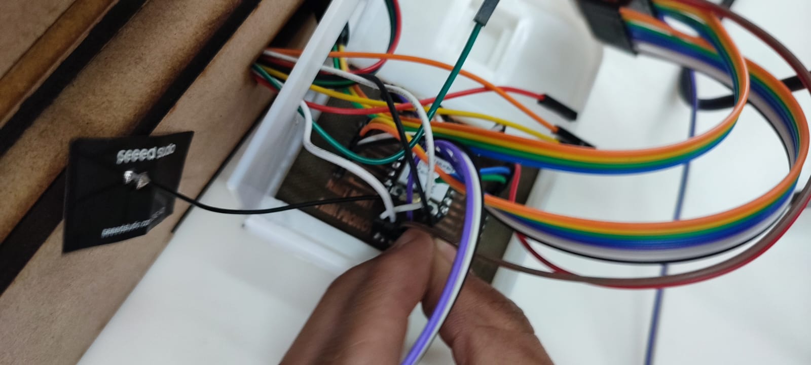
After the mechanical structure was positioned, the electrical system was organized inside the final design. This stage focused on testing the real cable paths, connecting the PCB to the sensors and actuators, and checking how the wiring could pass through the MDF structure without interfering with the movement of the lead screw or the reservoir.
The first wiring tests were done with the cables exposed. This made it possible to identify each signal line, check the connector orientation, and verify that the wires coming from the frame could reach the control board. The cable openings in the MDF structure were used as routing points so the electronics could move from a breadboard-style test into a more organized final assembly.
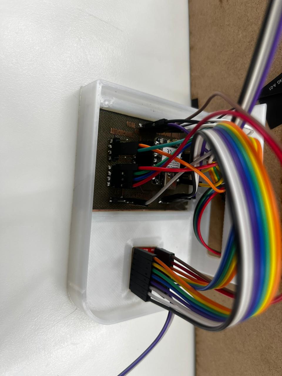
The printed case was used to give the PCB a defined position and to separate the electronic layer from the reservoir and plant area. The case also helped group the ribbon cable and jumper wires, reducing the risk of accidental disconnection during movement tests.
Electrical validation criteria
- Connector orientation: each cable was checked before powering the system.
- Cable reach: wires had to reach the PCB without tension or sharp bends.
- Movement clearance: wiring was kept away from the lead screw, motor shaft, and moving pot support.
- Sensor access: the humidity sensor and limit switch cables remained accessible for debugging.
- Case organization: the printed enclosure grouped the PCB and reduced exposed connections.
6. Reservoir and Orchid Pot Integration
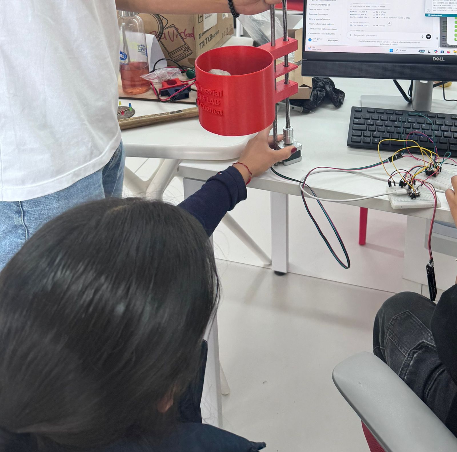
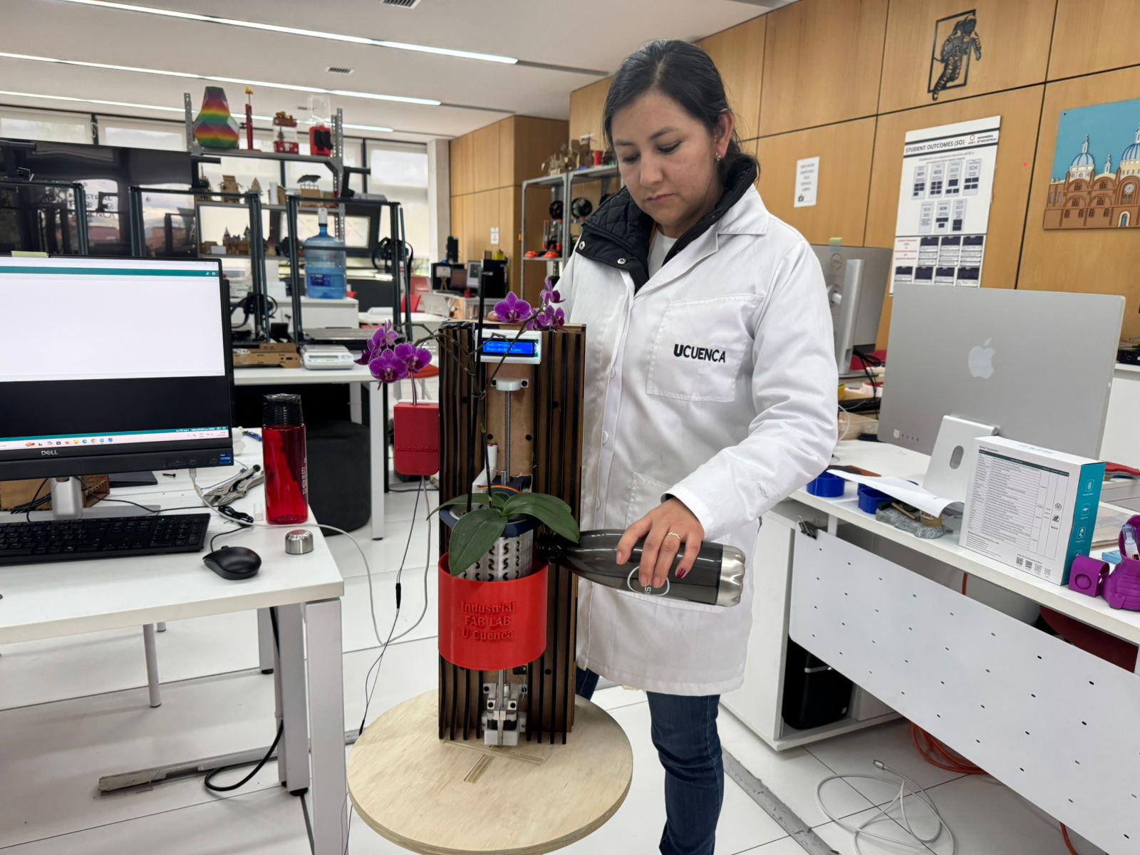
After the structure and motor support were positioned, the water reservoir and orchid pot were placed into the system. The red reservoir component was checked against the vertical motion module, while the orchid pot was used to verify scale, visibility, and plant clearance.
This step confirmed the relationship between the biological component and the mechanical motion. The reservoir had to move or sit close to the mechanism without colliding with the pot or plant, and the orchid needed enough space to remain visible and stable during the assembly test.
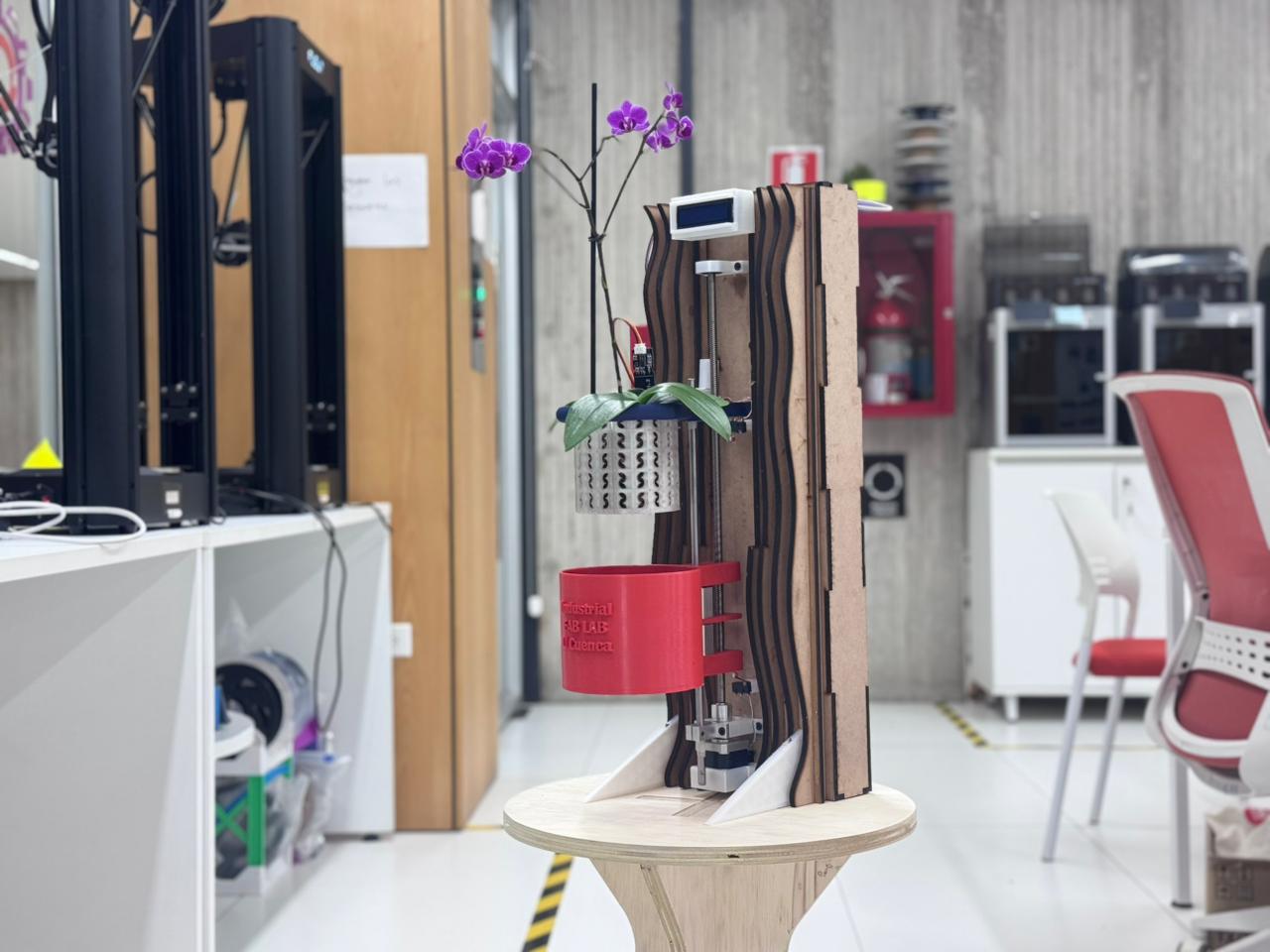
7. Final Tests and Mechanical Design Conclusions
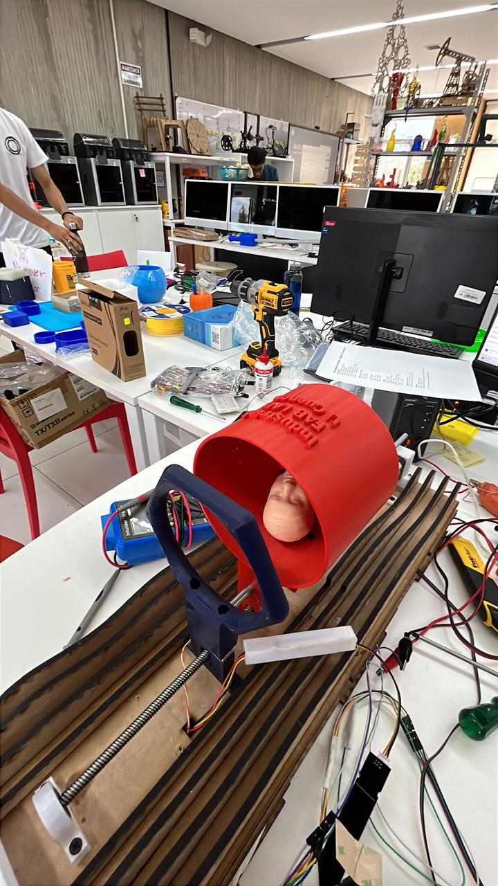
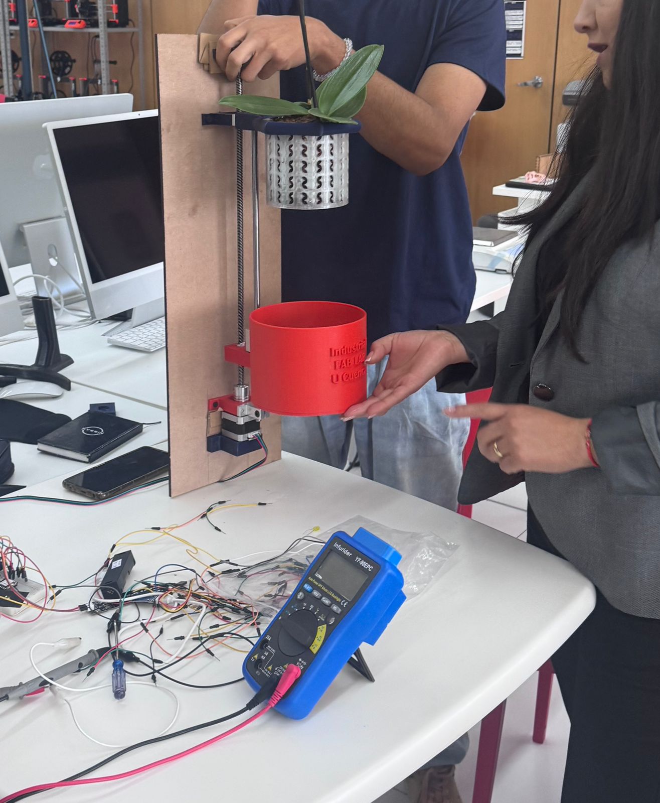
The final tests focused on checking how the components behaved together in the assembled prototype. The electronics controlled the system, the sensor wiring remained connected, the LCD was visible, the structure supported the orchid pot, and the reservoir was tested as part of the irrigation workflow.
For the final demonstration, the prototype was presented vertically with the orchid installed, the red reservoir in position, the sliced framework visible, and the electronic interface mounted on the front. Water was poured into the system to validate the irrigation concept and observe how the reservoir, plant container, structure, and electronics worked together.
Assembly validation checklist
- The motor and lead screw were tested before full structural integration.
- The bearing and printed supports were used to stabilize the moving axis.
- The electronic system was checked with sensor wiring and motor control connections.
- The MDF structure provided a vertical reference for the final mechanical assembly.
- The reservoir and orchid pot were positioned to verify scale, clearance, irrigation access, and presentation.
- The LCD and wiring case were visible and accessible during the final test.
- The final prototype workflow connects Mechanical Design with Electronics Production and System Integration.
10. Wall Frame Development : Computer-Aided Design & Computer-Controlled Cutting
Week 02 – Computer-Aided Design (Wall Frame Development)
The structural backbone of the OrquiWall Smart System is the Wall Frame. This component serves as the modular support structure where irrigation channels, electronic modules, and plant holders will be integrated. The design process was divided into two main phases: Rhino modeling and Grasshopper parametric optimization.
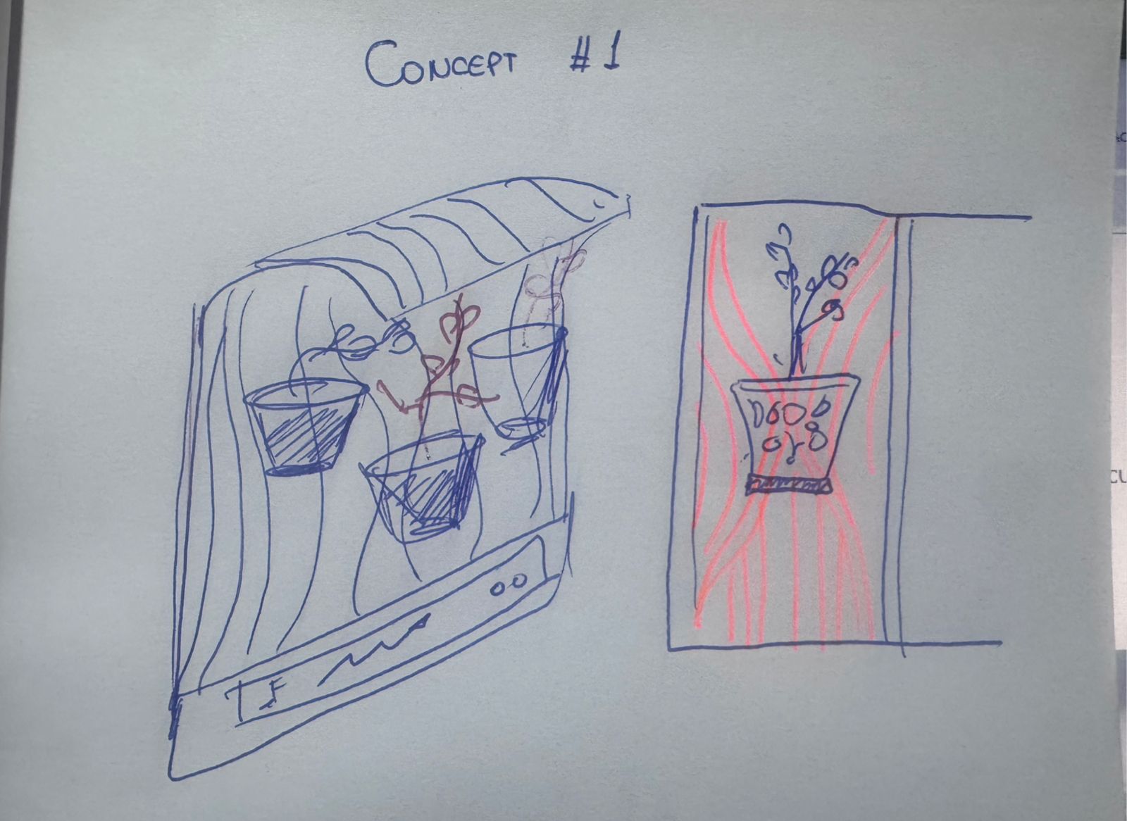
Concept01
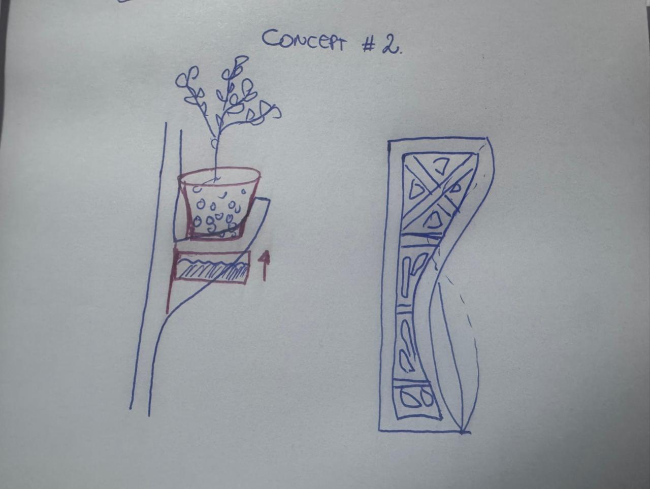
Concept02
Phase 1 – Base Geometry Modeling in Rhino
-
Step 1: Define Work Area
Set document units to centimeters. Define a base rectangle of 90 cm x 60 cm representing the total wall panel dimension.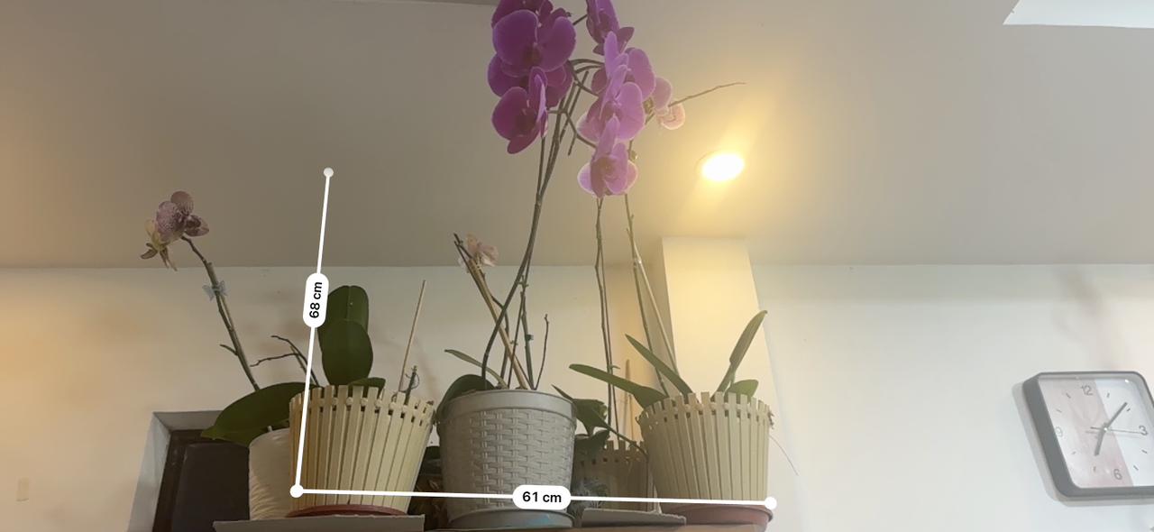
Concept01
Concept02
Concept03
- Step 2: Create Structural Frame Border
Offset the external rectangle 4 cm inward to generate a perimeter structural frame. This creates rigidity and mounting margins.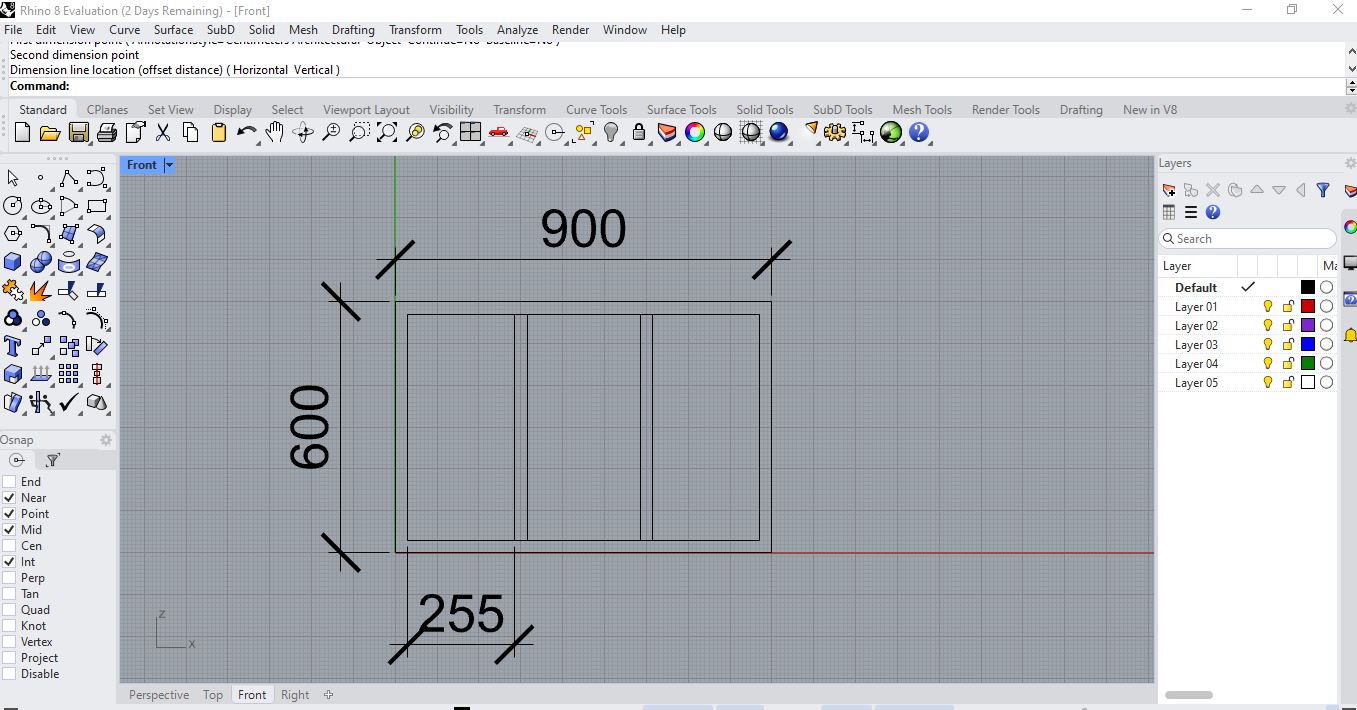
Concept01
Concept02
Concept03
Concept05
Concept06
Concept07
Assembly Process Video
⬇ Download Complete System (.3dm) ⬇ Download Single System (.3dm) ⬇ Download 3D Export (.OBJ / .3MF)- Step 3: Internal Grid Layout
Divide the interior surface into modular sections. A grid subdivision of 6 columns x 4 rows was created to allow modular plant holders.`r`n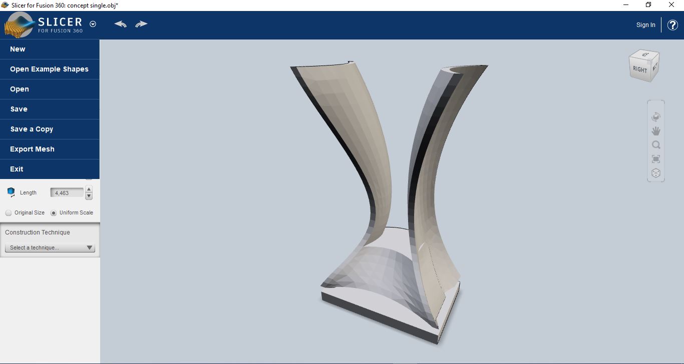
Concept01
Concept02
Concept03
Assembly Process Video
- Step 4: Mounting Points
Add circular holes (8 mm diameter) in corner and central intersections for wall anchoring and structural reinforcement.- Step 5: Assembly Slots
Create interlocking tabs designed for 6 mm MDF thickness. Slot width was defined initially as 6 mm before kerf compensation.The base geometry was verified for structural balance, material optimization, and mechanical feasibility.
Phase 2 – Parametric Optimization in Grasshopper
To allow scalability and future modular expansion, the frame was reconstructed parametrically in Grasshopper.
-
Step 1: Parameter Definition
Create sliders for:- Panel Width (default 90 cm)
- Panel Height (default 60 cm)
- Frame Thickness (4 cm)
- Grid Density (Rows & Columns)
- Material Thickness (6 mm)
-
Step 2: Dynamic Grid Generation
Use "Divide Domain²" and "Isotrim" to generate adjustable modular sections. -
Step 3: Slot Parametrization
Define slot width as: Material Thickness - Kerf Compensation Example: 6 mm – 0.15 mm = 5.85 mm -
Step 4: Structural Reinforcement Pattern
Generate diagonal or honeycomb reinforcement patterns to reduce weight while maintaining rigidity. -
Step 5: 2D Flattening for Fabrication
Bake geometry into Rhino and organize parts in a flat layout ready for laser cutting.
The parametric model allows resizing the system without redesigning the entire structure, ensuring scalability of the OrquiWall Smart System.
Week 03 – Computer-Controlled Cutting (Laser Cutting Process)
After validating the digital model, fabrication was performed using laser cutting technology.
Material Specifications
- Material: MDF
- Thickness: 6 mm
- Panel Dimensions: 90 cm x 60 cm
- Cutting Method: CO₂ Laser Cutter
Laser Cutting Workflow
-
Step 1: File Preparation
Export final geometry as DXF format. Ensure all cutting lines are vector paths. Color code:- Red – Cutting lines
- Blue – Engraving (if needed)
-
Step 2: Kerf Calibration
Perform a test cut on MDF 6 mm. Measure kerf using: Kerf = (Slot Width - Material Thickness) / 2 Adjust slot tolerances accordingly. -
Step 3: Machine Setup
Focus laser to material thickness. Configure power and speed parameters suitable for MDF 6 mm. Example baseline:- Power: 65–75%
- Speed: 15–20 mm/s
-
Step 4: Cutting Execution
Place MDF sheet (90x60 cm) securely. Run cutting job and supervise process. -
Step 5: Post-Processing
Remove burnt residues. Light sanding of edges. Test-fit all interlocking joints. -
Step 6: Structural Assembly
Assemble slots and validate:- Mechanical rigidity
- Dimensional accuracy
- Wall mounting stability
The final result is a fully fabricated parametric wall frame, optimized for modular plant integration, electronic mounting, and irrigation routing.
- Step 2: Create Structural Frame Border