WEEK 09 – Input Devices
Group Assignment
The group assignment focused on probing an input device's analog levels and digital signals. This helped us understand how sensors produce measurable values and how those values can be interpreted by a microcontroller.
The complete group documentation is available in the Fab Academy group page.
Individual Assignment
Water Level Sensor Board using XIAO ESP32-C3
This assignment focuses on the design, fabrication, programming, and testing of an input device. For this week, I designed and fabricated my own PCB based on the reference of the FabXiao, using a Seeed Studio XIAO ESP32-C3 as the main microcontroller.
The purpose of this project was to create a board capable of reading data from a water level sensor. The sensor generates a signal when it is inserted into water, allowing the microcontroller to detect the presence or level of water and display the information through the Arduino IDE Serial Monitor.
The board was designed to connect the sensor to the XIAO ESP32-C3, process the analog signal, and provide readable values that can be used for future applications such as water monitoring, tank level detection, environmental sensing, or automated systems.
1. Assignment Objective
Main Objective
The main objective of this assignment was to design and fabricate a custom PCB that can read data from an input device. In this case, the input device is a water level sensor connected to an ESP32 XIAO C3 microcontroller.
| Objective | Description |
|---|---|
| Design a custom PCB | Create my own board based on the FabXiao reference. |
| Use an input sensor | Connect a water level sensor to detect contact with water. |
| Use the XIAO ESP32-C3 | Control and read the sensor data using the ESP32 XIAO C3. |
| Fabricate the PCB | Use a 90 watt fiber laser machine to produce the circuit board. |
| Program the board | Use Arduino IDE to read and display sensor values. |
| Validate the input device | Test the sensor in dry and wet conditions to observe changes in readings. |
2. Project Concept
The project consists of a water level sensing system. When the sensor is outside water, the microcontroller reads a low or baseline value. When the sensor is inserted into water, the electrical behavior of the sensor changes and the XIAO ESP32-C3 receives a different signal. This change is interpreted as the presence of water.
| System Element | Function |
|---|---|
| Water level sensor | Detects contact with water and generates an input signal. |
| Custom PCB | Provides electrical connections between the sensor and the XIAO ESP32-C3. |
| XIAO ESP32-C3 | Reads the sensor signal and processes the input data. |
| Arduino IDE | Used to program the microcontroller and observe the sensor readings. |
| Serial Monitor | Displays the analog values and water detection status. |
3. Materials and Components
The following materials were used to complete the input devices assignment. These components were selected to allow the design, fabrication, assembly, and testing of a functional board capable of reading a water level sensor.
| Material / Component | Quantity | Purpose |
|---|---|---|
| Seeed Studio XIAO ESP32-C3 | 1 | Main microcontroller used to read and process sensor values. |
| Water level sensor | 1 | Input device used to detect water presence or level. |
| Copper clad board | 1 | Base material for the custom PCB. |
| Header pins | As needed | Used to connect the XIAO ESP32-C3 and sensor to the board. |
| Jumper wires | As needed | Used for temporary tests and external connections. |
| Solder wire | As needed | Used to fix electronic components to the PCB. |
| USB-C cable | 1 | Used to program and power the XIAO ESP32-C3. |
| Water container | 1 | Used to test the sensor response when inserted into water. |
| Multimeter | 1 | Used to verify continuity and detect possible short circuits. |
4. Software Used
Arduino IDE
Arduino IDE was used to program the XIAO ESP32-C3 and read the data obtained from the water level sensor. The Serial Monitor was used to display the sensor values in real time.
KiCad
KiCad was used to design the schematic and PCB layout of the custom input board. The board was created using the FabXiao as a design reference.
Laser Software
The laser software was used to prepare and send the PCB design to the 90 watt fiber laser machine for fabrication.
5. Reference Board: FabXiao
For this assignment, the FabXiao was used as a design reference. This helped me understand how the XIAO microcontroller can be integrated into a custom PCB and how to organize the connections for power, ground, and input/output pins.
The objective was not only to copy the reference board, but to use it as a starting point to develop my own input device board. I adapted the concept to include the connection for a water level sensor and the necessary pins for reading the sensor signal.
| FabXiao Reference Element | How It Was Used in My Design |
|---|---|
| XIAO footprint | Used as a reference to correctly place and connect the XIAO ESP32-C3. |
| Power pins | Used to organize 3.3V and GND connections for the sensor. |
| GPIO pins | Used to select a suitable analog input pin for the water level sensor. |
| Compact board layout | Used as a guide to create a small and functional custom PCB. |
6. Water Level Sensor Explanation
The water level sensor is an input device that changes its output signal when it comes into contact with water. The sensor usually has conductive tracks that interact with the water. When water touches the sensing area, the electrical resistance changes and the sensor produces a measurable analog signal.
The XIAO ESP32-C3 reads this signal through an analog input pin. The value can be observed in the Serial Monitor. When the sensor is dry, the value is low or close to a baseline. When the sensor is inserted into water, the value increases or changes depending on the amount of contact.
| Sensor Condition | Expected Reading | Interpretation |
|---|---|---|
| Sensor dry | Low or baseline analog value | No water detected. |
| Sensor partially in water | Medium analog value | Water is detected at a low or medium level. |
| Sensor inserted deeper in water | Higher analog value | Greater water contact or higher level detected. |
Important: The water level sensor should be used carefully. Only the sensing area should be inserted into water. The electronic connections and the microcontroller must remain dry.
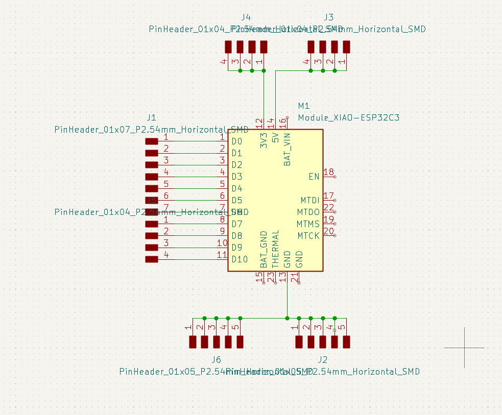
7. Board Design in KiCad
The PCB design process started in KiCad. First, I created the schematic by placing the XIAO ESP32-C3 and the connector for the water level sensor. The sensor requires power, ground, and a signal connection to an analog input pin of the microcontroller.
The schematic was designed to keep the circuit simple, functional, and easy to fabricate. Since the objective of the assignment was to read an input device, the most important connection was the signal line between the sensor and the analog input pin.
Schematic Design Steps
- Create a new KiCad project for Week 09.
- Add the XIAO ESP32-C3 symbol.
- Add a connector for the water level sensor.
- Connect the sensor VCC pin to 3.3V.
- Connect the sensor GND pin to GND.
- Connect the sensor signal pin to an analog input pin of the XIAO ESP32-C3.
- Add labels to make the schematic easier to understand.
- Run the Electrical Rules Check.
- Correct warnings or unconnected pins.
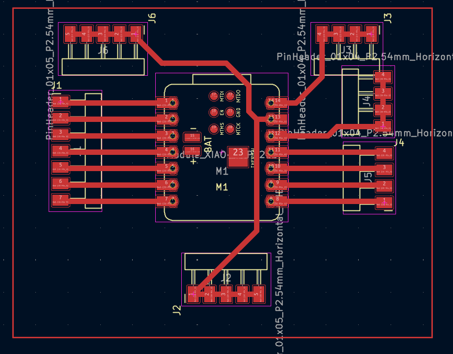
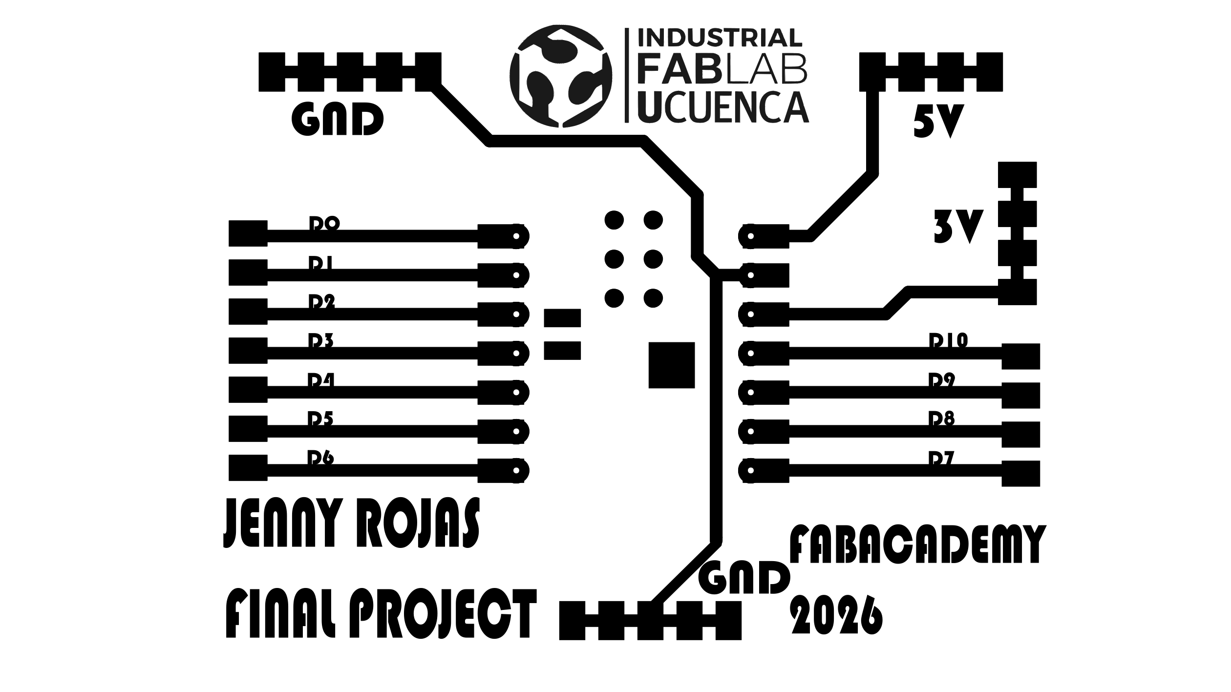
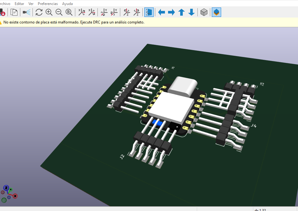
8. PCB Layout Design
After validating the schematic, I moved to the PCB layout. The XIAO ESP32-C3 footprint was placed in a central and accessible position so that the USB-C port could be reached easily for programming. The connector for the water level sensor was placed near the edge of the board to simplify the connection with the sensor.
The traces were routed with enough width and separation to be fabricated with the fiber laser process. The board outline was also defined according to the size required for the circuit.
PCB Layout Steps
- Assign footprints to the XIAO ESP32-C3 and sensor connector.
- Open the PCB editor in KiCad.
- Import the components from the schematic.
- Place the XIAO ESP32-C3 footprint.
- Place the sensor connector near the board edge.
- Route the 3.3V, GND, and signal traces.
- Verify trace width and clearance.
- Define the board outline.
- Run the Design Rules Check.
- Export the fabrication files.
9. Design Rules and Considerations
| Design Consideration | Application in This Board |
|---|---|
| Analog Input Selection | The water level sensor signal was connected to an ADC-capable pin (e.g., A0/A1) on the XIAO ESP32-C3 to read varying physical conditions. |
| 3.3V Logic & Power | Since the XIAO ESP32-C3 operates strictly on 3.3V logic, the water level sensor was powered and interfaced accordingly to prevent overvoltage. |
| Trace Width | Traces were designed with a custom width robust enough to withstand the 90W fiber laser engraving process without breaking. |
| Trace Clearance (Spacing) | A safe isolation gap was maintained between traces to prevent short circuits and ensure clean separation after the laser engraving. |
| Connector Placement | The water sensor header was placed near the edge of the custom PCB for clean wire routing and easy integration. |
| USB-C Access | The XIAO ESP32-C3 was oriented at the board's edge to guarantee unobstructed access to the USB port for programming via Arduino IDE. |
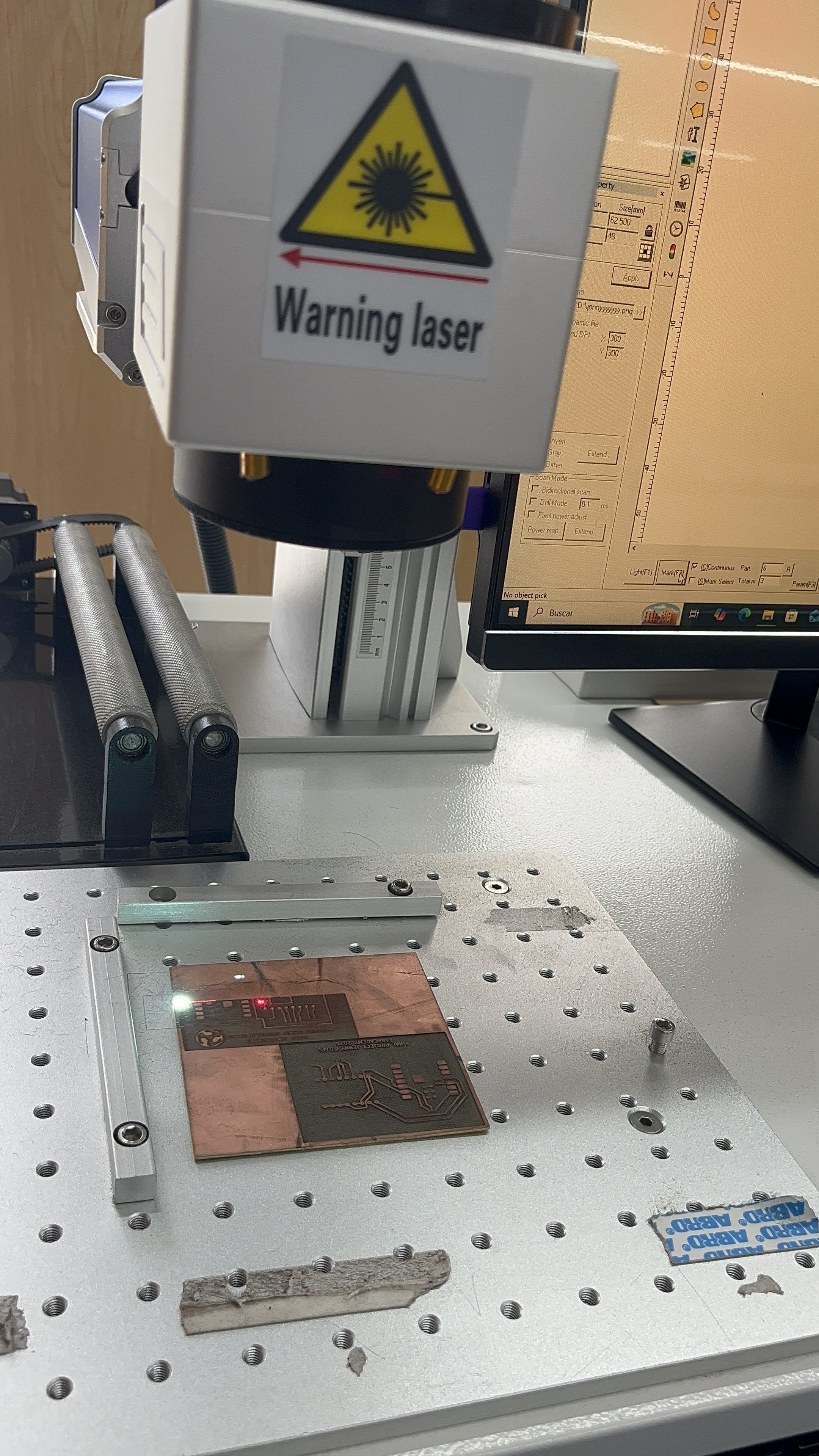
10. Fabrication Equipment: 90 W Fiber Laser Machine
The PCB was fabricated using a 90 watt fiber laser machine. This equipment uses a focused laser beam to remove material from the copper surface of the board. In this case, the laser was used to isolate the copper traces and create the electrical paths of the PCB.
The fiber laser is especially useful for working with metallic surfaces because it can engrave and remove thin layers of copper with precision. However, the parameters must be adjusted carefully to avoid burning the substrate or damaging the copper traces.
| Equipment Feature | Description |
|---|---|
| Machine type | Fiber laser engraving machine. |
| Power | 90 watts. |
| Application | PCB copper engraving and trace isolation. |
| Material | Single-sided copper clad board. |
| Important parameters | Power, speed, frequency, focus, and number of passes. |
| Safety | Use appropriate protection, avoid reflective exposure, and supervise the engraving process. |
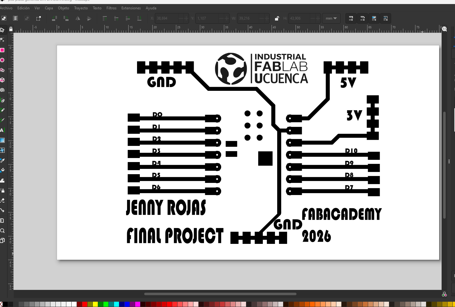
11. PCB Fabrication Process
Fabrication Steps
- Export the PCB trace design from KiCad.
- Prepare the file for the laser software.
- Clean the copper board before engraving.
- Place the copper board on the laser bed.
- Fix the board to avoid movement.
- Import the trace file into the laser software.
- Check the scale and orientation of the design.
- Adjust the focus height of the fiber laser.
- Configure the laser parameters.
- Run the engraving process.
- Inspect the copper removal.
- Repeat the pass if necessary.
| Fabrication Stage | Purpose | Risk to Control |
|---|---|---|
| Cleaning the copper board | Remove grease and dust before engraving. | Poor engraving quality if the surface is dirty. |
| Focusing the laser | Ensure that the laser energy is concentrated on the copper surface. | Incomplete copper removal if focus is incorrect. |
| Engraving traces | Remove copper to isolate the electrical paths. | Burned substrate or broken traces. |
| Inspection | Verify that there are no copper bridges or broken paths. | Short circuits or open circuits. |
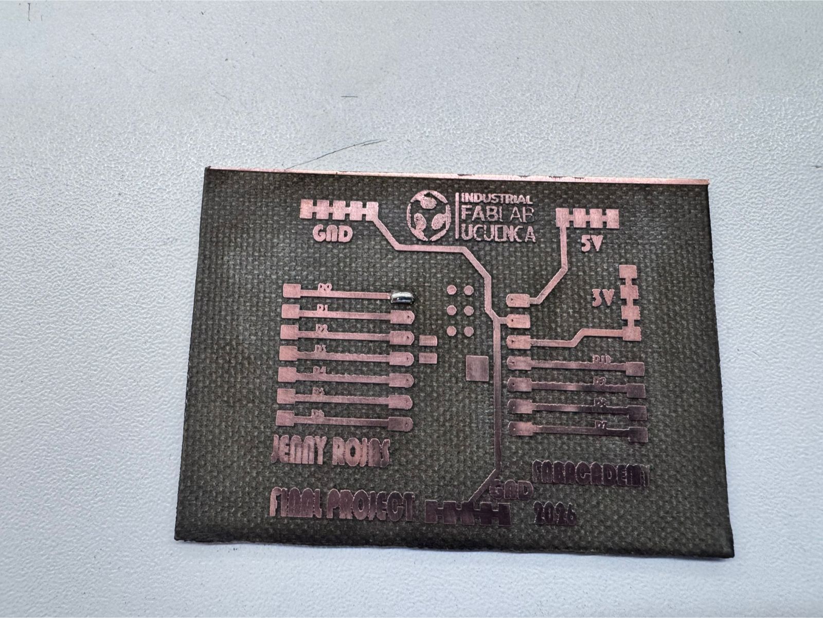
12. Inspection After Laser Engraving
After the engraving process, I inspected the PCB to confirm that the traces were clearly defined. This step was essential because a small copper bridge can create a short circuit, while an incomplete trace can prevent the sensor from working.
| Inspection Point | Expected Condition |
|---|---|
| Trace continuity | The signal, VCC, and GND traces must be complete. |
| Isolation between traces | There must be no unwanted copper bridges. |
| Pad condition | The pads must remain large enough for soldering and drilling. |
| Board surface | The substrate should not be excessively burned. |
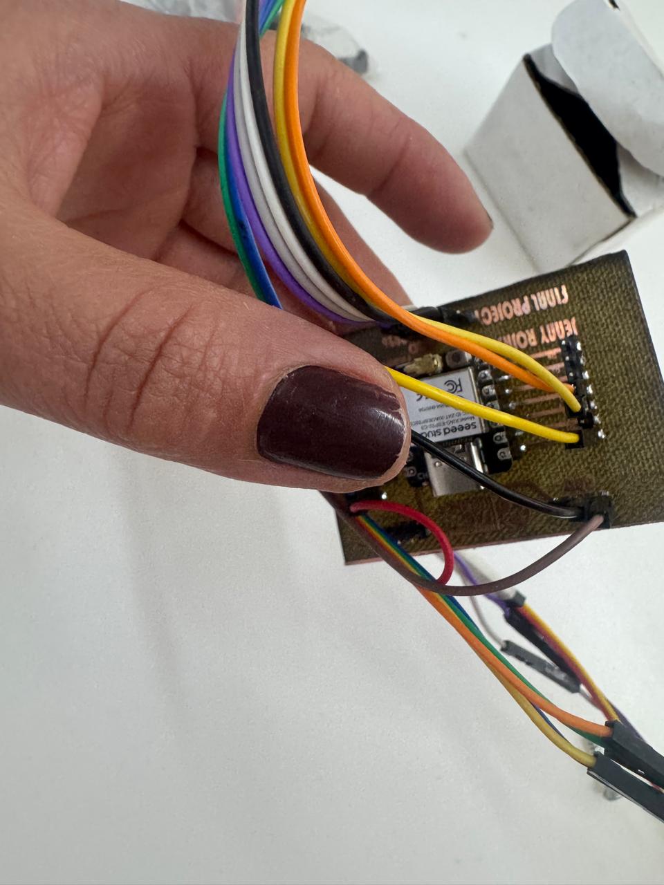
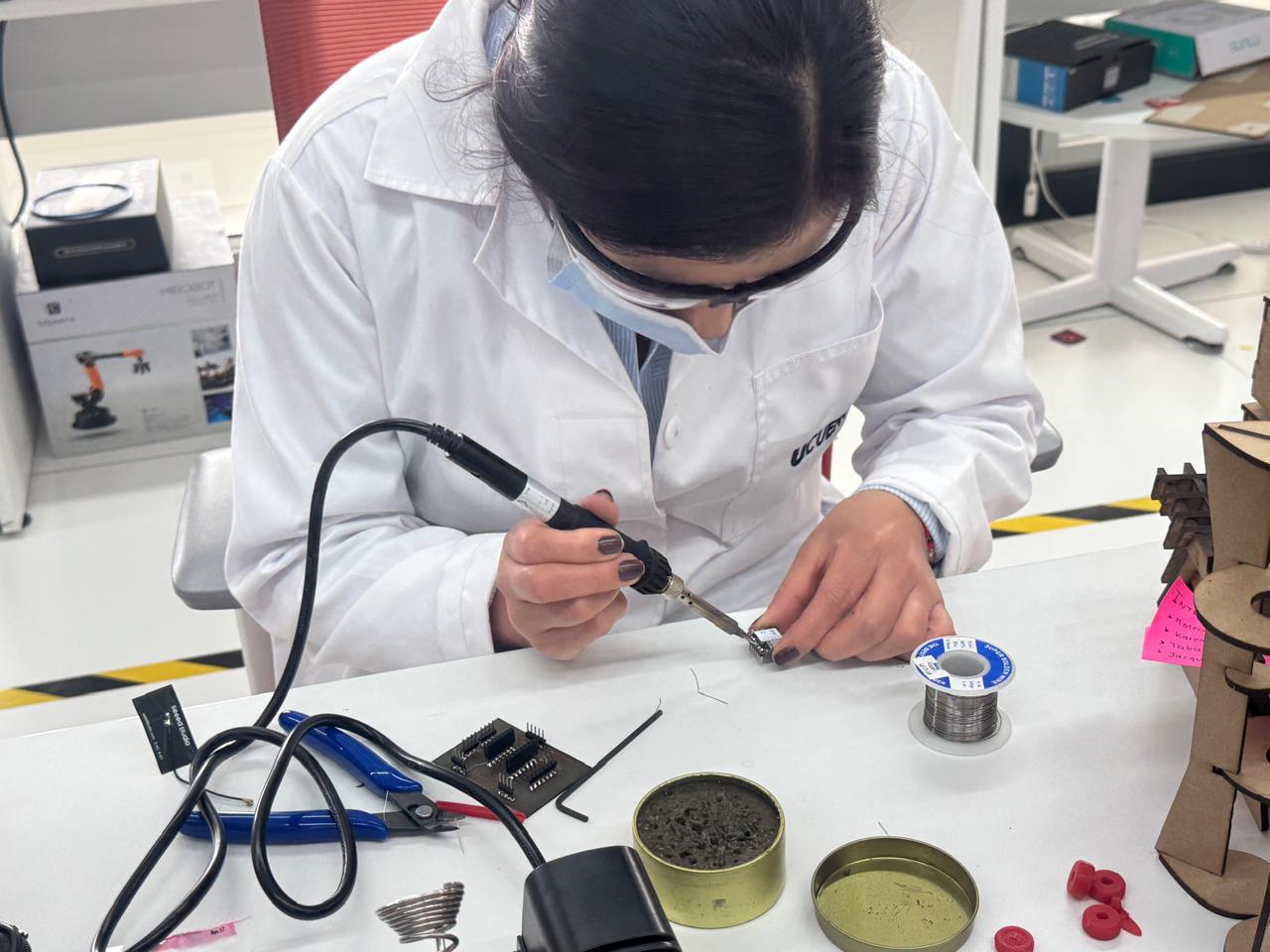
13. Soldering the Board
Once the board was engraved and drilled, I soldered the components. The main soldered parts were the header pins for the XIAO ESP32-C3 and the connector for the water level sensor.
During soldering, I checked that there were no solder bridges between adjacent pads and that each joint was mechanically stable and electrically connected.
Soldering Steps
- Prepare the soldering iron and solder wire.
- Place the header pins for the XIAO ESP32-C3.
- Solder the header pins carefully.
- Place the sensor connector.
- Solder the sensor connector pads.
- Inspect each solder joint.
- Check for solder bridges.
- Clean the board after soldering.
| Soldering Check | Description |
|---|---|
| Header alignment | The XIAO ESP32-C3 headers must be straight and aligned. |
| Sensor connector | The connector must be stable and correctly soldered. |
| Solder bridges | No accidental connection between neighboring pads. |
| Cold joints | Solder joints must be shiny and firm. |
14. Arduino IDE Setup
The board was programmed using Arduino IDE. Before uploading the code, I selected the correct board and port for the XIAO ESP32-C3. The Serial Monitor was configured to display the sensor readings.
Arduino IDE Setup Steps
- Connect the XIAO ESP32-C3 to the computer using a USB-C cable.
- Open Arduino IDE.
- Select the correct ESP32 board package.
- Select the XIAO ESP32-C3 board.
- Select the correct serial port.
- Open a new sketch.
- Write or paste the sensor reading code.
- Compile the code.
- Upload the code to the board.
- Open the Serial Monitor.

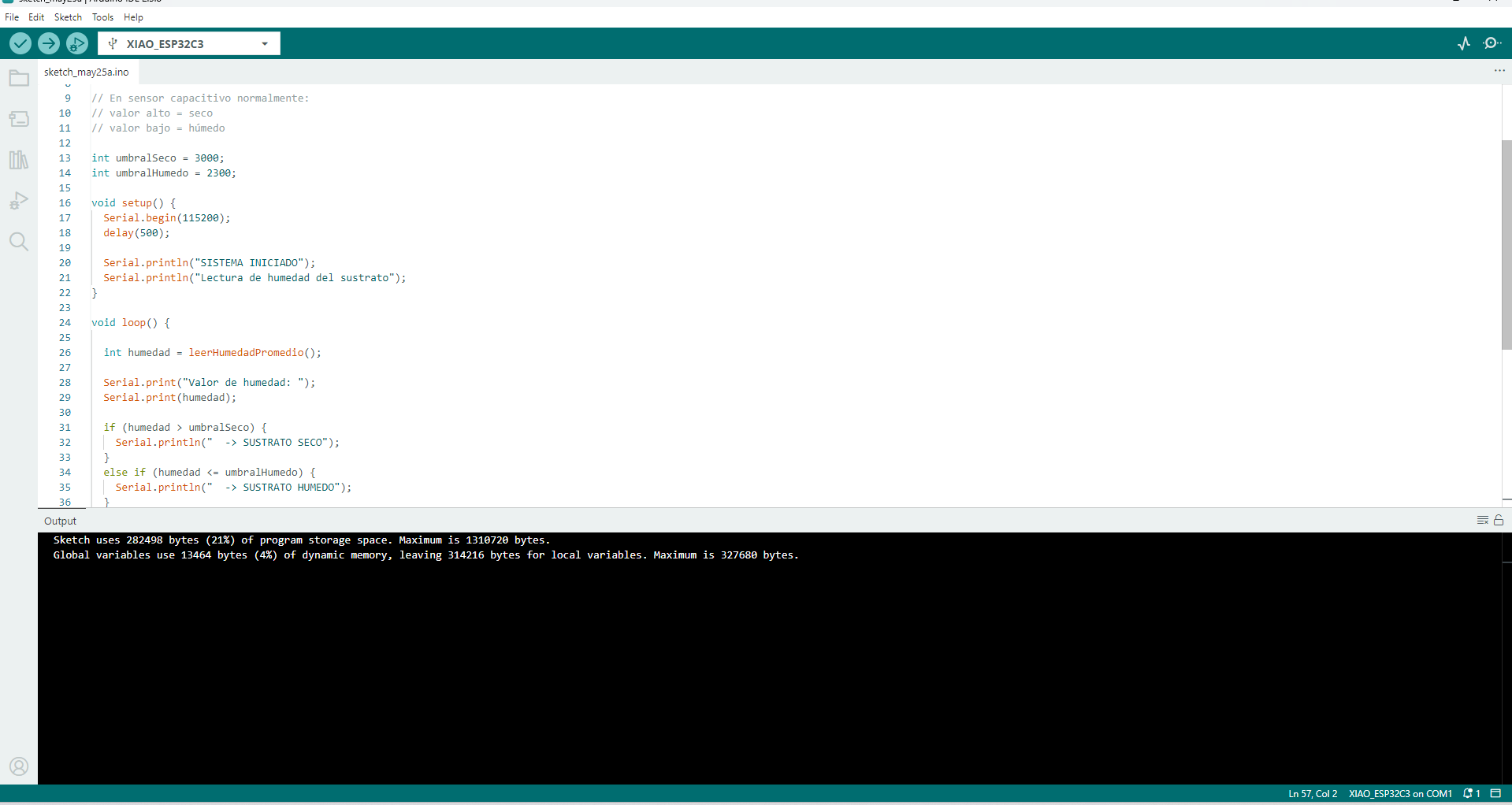
15. Programming the Water Level Sensor
The program reads the analog value from the water level sensor and prints the result in the Serial Monitor. A threshold value is used to determine whether water is detected or not.
The threshold can be adjusted after testing because the sensor value may change depending on the amount of water, the sensor type, and the quality of the electrical connection.
const int sensorPin = A0;
int sensorValue = 0;
int threshold = 500;

void setup() {
  Serial.begin(115200);
  delay(1000);

  Serial.println("Week 09 - Input Devices");
  Serial.println("Water Level Sensor Test with XIAO ESP32-C3");
}

void loop() {
  sensorValue = analogRead(sensorPin);

  Serial.print("Sensor value: ");
  Serial.print(sensorValue);

  if (sensorValue > threshold) {
    Serial.println("  | Water detected");
  } else {
    Serial.println("  | No water detected");
  }

  delay(500);
}
Note: The pin A0 must be adjusted according to the analog pin used in the final PCB design.
The threshold value must also be calibrated after observing the real sensor readings.
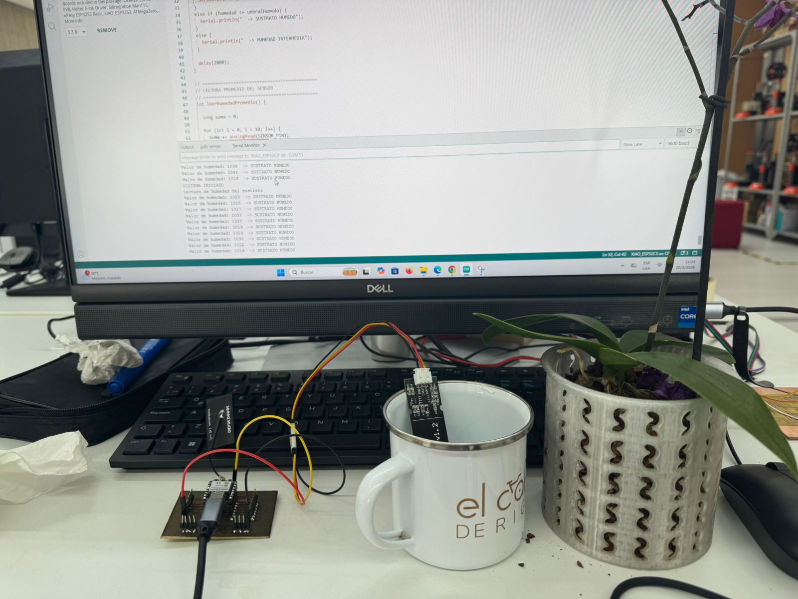
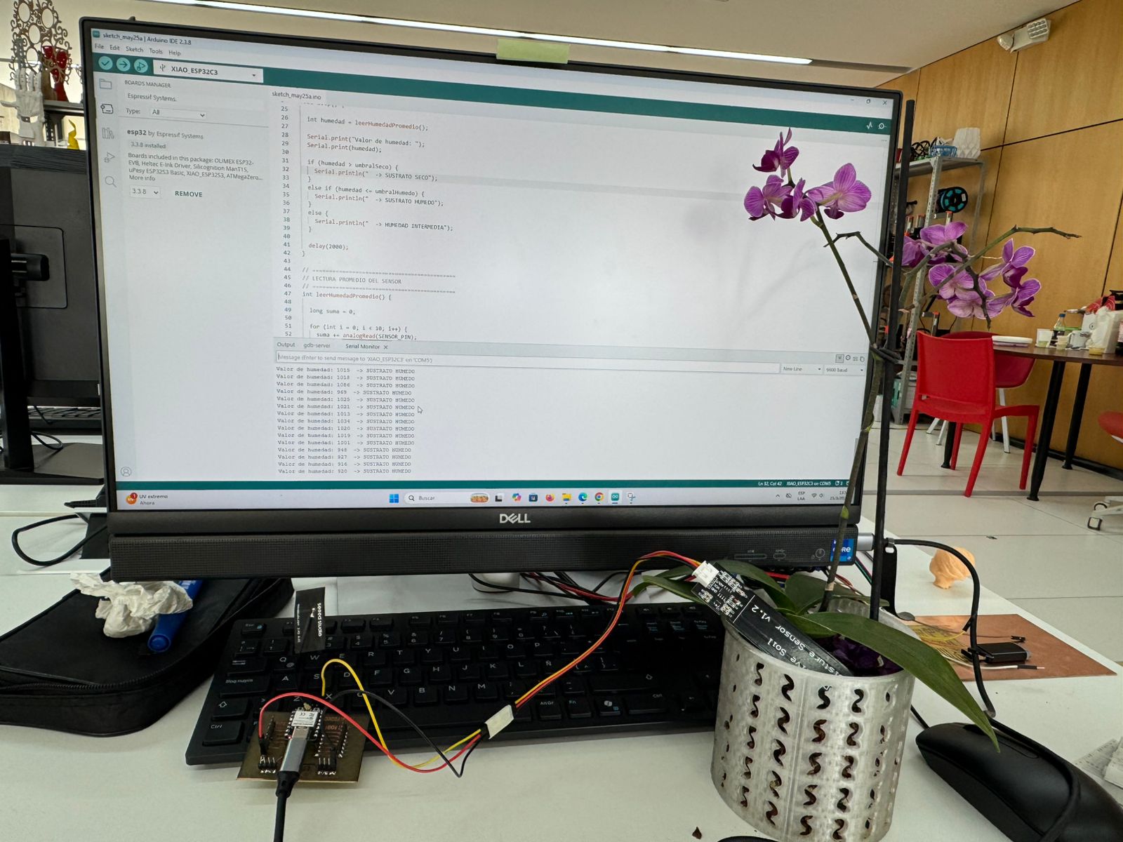
16. Testing the Sensor
After uploading the code, I opened the Serial Monitor and observed the sensor readings. First, I tested the sensor in dry condition. Then, I inserted the sensing area into water and observed how the values changed.
Testing Steps
- Connect the board to the computer.
- Open the Serial Monitor at 115200 baud.
- Observe the value with the sensor dry.
- Insert only the sensing area of the sensor into water.
- Observe the change in analog readings.
- Adjust the threshold value if necessary.
- Repeat the test several times to confirm stable behavior.
| Test Condition | Expected Result | Observation |
|---|---|---|
| Sensor dry | Low analog value | The Serial Monitor should display “No water detected”. |
| Sensor partially inserted in water | Medium analog value | The reading should increase compared to the dry condition. |
| Sensor inserted deeper in water | Higher analog value | The Serial Monitor should display “Water detected”. |
17. Data Interpretation
The values obtained from the water level sensor represent the electrical response of the sensor. These readings allow the microcontroller to determine whether water is present or not.
The most important part of this process was comparing the sensor value in different conditions. By observing the dry and wet values, I could define a threshold that separates the “No water” state from the “Water detected” state.
| Reading Type | Meaning | Action |
|---|---|---|
| Low value | The sensor is dry or has very little contact with water. | Display “No water detected”. |
| Medium value | The sensor has partial contact with water. | Indicate initial water detection. |
| High value | The sensor has greater contact with water. | Display “Water detected”. |
18. Problems and Solutions
| Problem | Possible Cause | Solution |
|---|---|---|
| The sensor value does not change. | Wrong signal pin, damaged sensor, or incorrect wiring. | Check the sensor connector, verify the analog pin, and test the sensor with jumper wires. |
| The readings are unstable. | Poor connection, water movement, or noise in the signal. | Check solder joints, secure the sensor, and average several readings in the code. |
| The board is not detected by the computer. | USB cable, driver, or board selection issue. | Use a data USB cable, install drivers if needed, and select the correct board and port. |
| There is a short circuit. | Copper bridge or solder bridge between traces. | Inspect the board, clean copper residues, and remove solder bridges. |
| The laser engraving is incomplete. | Incorrect focus, low power, or high speed. | Adjust focus and laser parameters, then repeat the engraving process. |
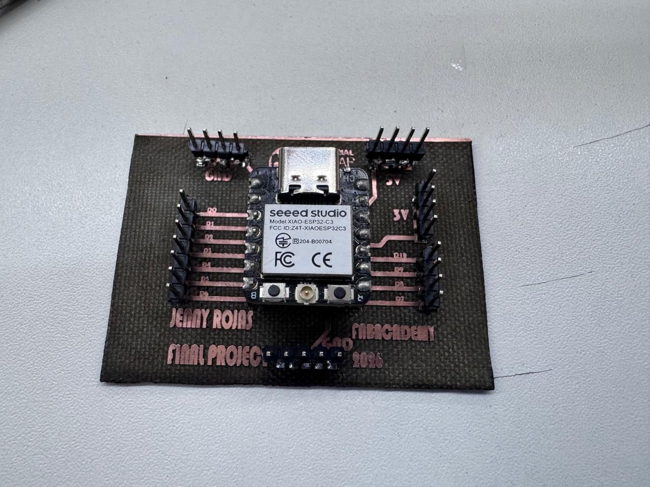
19. Results
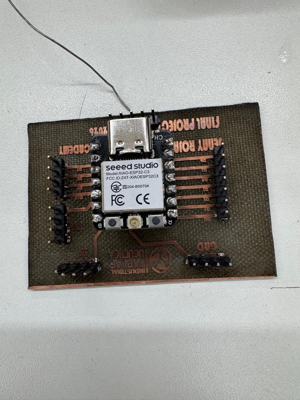
The final board was able to read data from the water level sensor using the XIAO ESP32-C3. The sensor values were displayed in the Arduino IDE Serial Monitor.
When the sensor was dry, the readings remained in a lower range. When the sensing area was inserted into water, the readings changed, allowing the microcontroller to identify the presence of water.
This confirmed that the board was working as an input device system and that the XIAO ESP32-C3 was able to receive, process, and display sensor data.
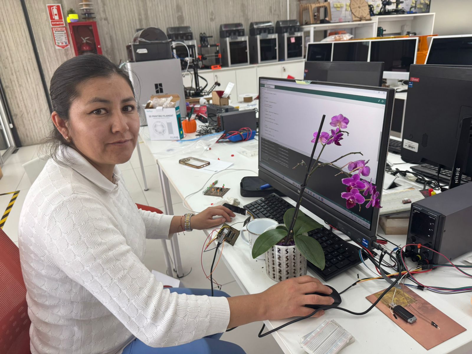
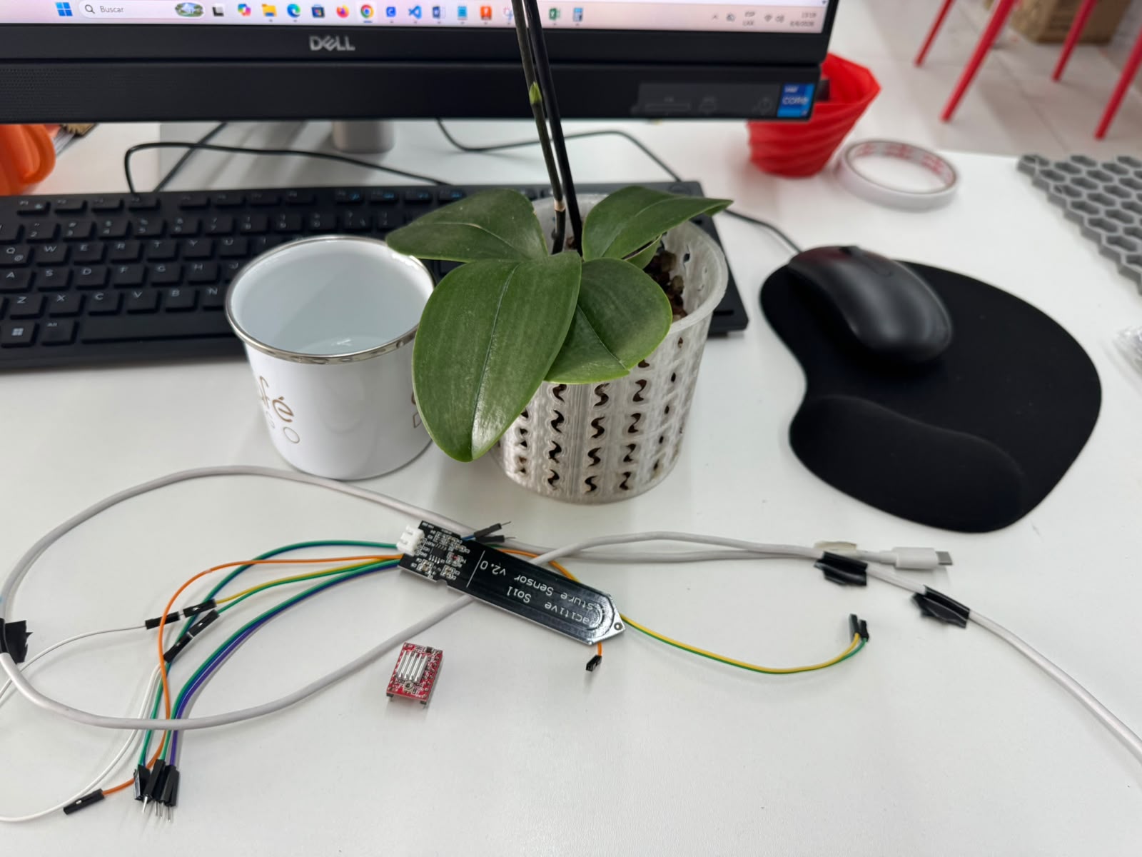
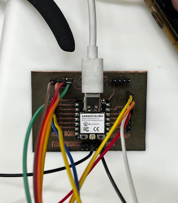
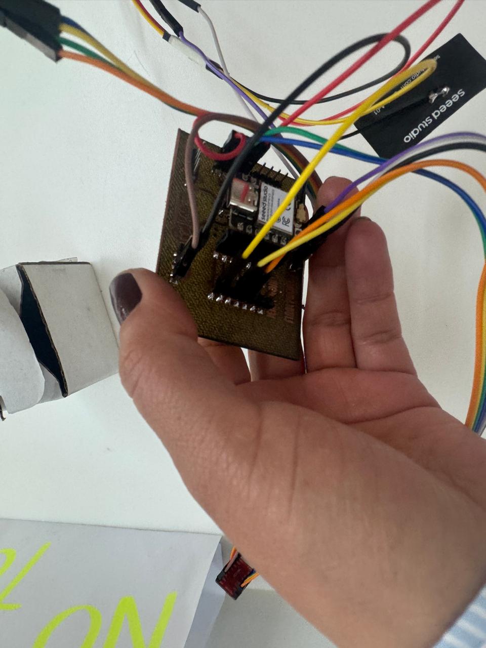
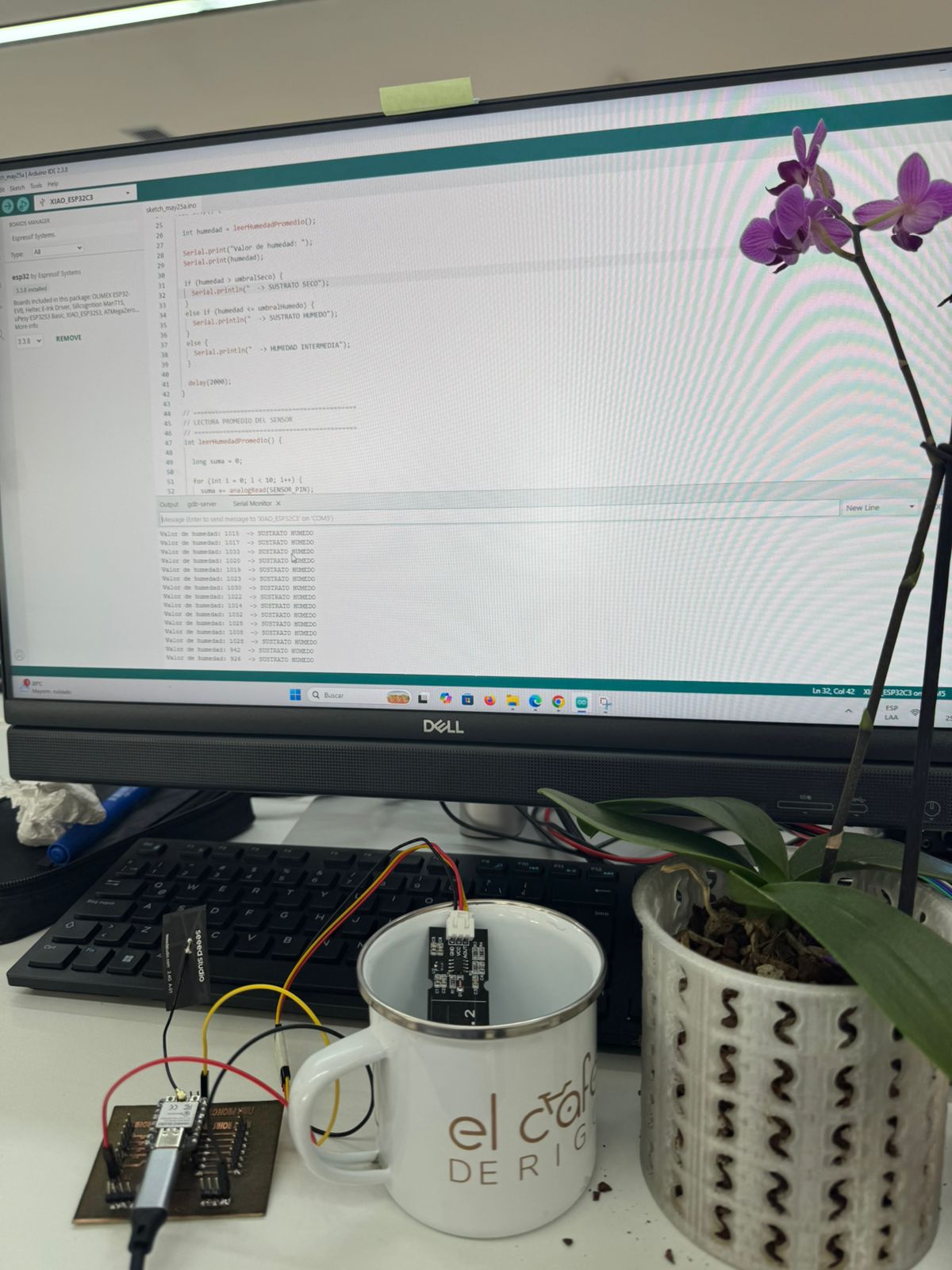
Input Process Hero Shot
This final hero shot shows the complete input device workflow: the custom PCB with the XIAO ESP32-C3 is connected to the computer through USB-C, the humidity sensor is connected to the PCB, and Arduino IDE is used to upload the program and observe the live data in the Serial Monitor.
The sensor works as an analog input. One wire provides power, one wire connects to ground, and
the signal wire goes to the analog input pin routed on the XIAO PCB. When the sensing area is
placed in water or humid substrate, the electrical response changes. The XIAO reads this value
with analogRead(), compares it with calibrated thresholds, and sends the result to
the Serial Monitor.
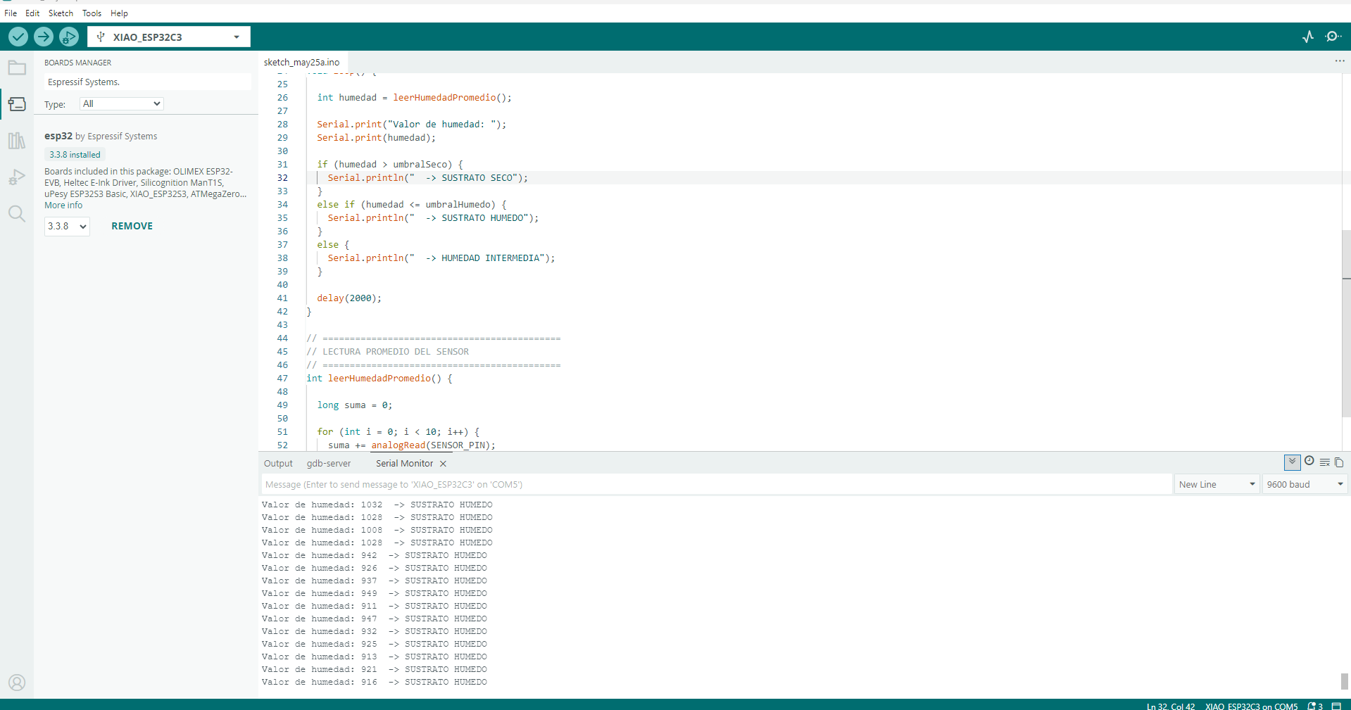
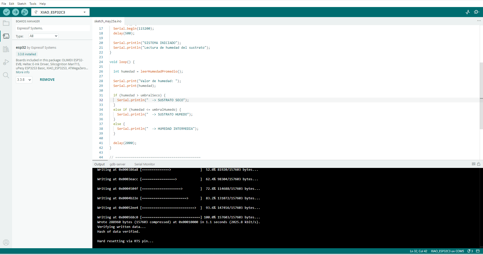
In Arduino IDE I selected the XIAO_ESP32C3 board and the correct COM port,
uploaded the sketch, and opened the Serial Monitor. The program prints values such as
Valor de humedad: 1032 -> SUSTRATO HUMEDO, confirming that the PCB, sensor
connection and code are working together.
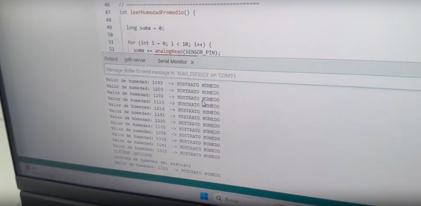
Humidity Sensor Serial Monitor Values
The following table summarizes the humidity sensor values observed in the Arduino IDE Serial Monitor during the input device test. The readings were obtained from the analog signal of the sensor connected to the XIAO ESP32-C3. In this test, the substrate was classified as SUSTRATO HUMEDO.
| No. | Humidity Sensor Value | Printed Status | Interpretation |
|---|---|---|---|
| 1 | 1093 | SUSTRATO HUMEDO | The substrate contains moisture. |
| 2 | 1203 | SUSTRATO HUMEDO | The sensor detects a humid condition. |
| 3 | 1202 | SUSTRATO HUMEDO | The reading remains in the wet range. |
| 4 | 1113 | SUSTRATO HUMEDO | The substrate is still classified as wet. |
| 5 | 1216 | SUSTRATO HUMEDO | The analog value confirms humidity presence. |
| 6 | 1191 | SUSTRATO HUMEDO | The sensor response is stable. |
| 7 | 1220 | SUSTRATO HUMEDO | The substrate remains humid. |
| 8 | 1160 | SUSTRATO HUMEDO | The reading is consistent with previous values. |
| 9 | 1075 | SUSTRATO HUMEDO | The value is lower but still in the humid range. |
| 10 | 1039 | SUSTRATO HUMEDO | The substrate is still detected as wet. |
| 11 | 1041 | SUSTRATO HUMEDO | The reading confirms the humid condition. |
| 12 | 1015 | SUSTRATO HUMEDO | The reading remains in the wet range. |
| 13 | 1020 | SUSTRATO HUMEDO | The final value confirms the same humid condition. |
Data Analysis
| Parameter | Result | Technical Meaning |
|---|---|---|
| Minimum observed value | 1015 | Lowest analog value recorded during the test. |
| Maximum observed value | 1220 | Highest analog value recorded during the test. |
| Approximate average value | 1122 | The average value confirms a stable humid substrate condition. |
| Sensor status | SUSTRATO HUMEDO | The program interpreted the readings as wet substrate. |
| Input device validation | Successful | The humidity sensor, custom PCB, XIAO ESP32-C3, and code worked together correctly. |
Discussion of Results
The extracted values show that the humidity sensor produced analog readings between 1015 and 1220. Although the values are not identical, they remain inside the same wet range and the program classified every sample as SUSTRATO HUMEDO. This behavior is expected because analog sensors can vary slightly depending on the amount of contact with the substrate, the pressure on the sensing area, the electrical connection, and small changes in moisture distribution.
The important result is that the status stayed consistent during the test. The XIAO ESP32-C3 was able to read the analog signal, compare it with the programmed threshold, and print a clear condition in the Serial Monitor. This validates the input device workflow because the physical condition of the substrate was converted into readable digital information.
Conclusion: The humidity sensor produced consistent analog values between approximately 1015 and 1220. The Arduino IDE Serial Monitor classified all readings as SUSTRATO HUMEDO, confirming that the input device was working correctly and that the substrate had enough moisture during the test.
20. Download Files
The following buttons can be used to download the project files, including the KiCad design, fabrication files, and Arduino code for the water level sensor test.
22. Learning Outcomes
Through this assignment, I learned how to:
- Design a custom input device PCB based on a reference board.
- Use the FabXiao as a guide for integrating the XIAO ESP32-C3.
- Connect a water level sensor to a microcontroller.
- Read analog values using Arduino IDE.
- Use the Serial Monitor to observe real-time sensor data.
- Fabricate a PCB using a 90 watt fiber laser machine.
- Solder and inspect a custom PCB.
- Use a multimeter to verify continuity and avoid short circuits.
- Calibrate a threshold value for sensor interpretation.
- Validate a functional input device system.
22. Final Reflection
This assignment helped me understand how a physical variable can be converted into digital data using an input device. In this case, the physical variable was the presence or level of water, and the sensor transformed that condition into an electrical signal that the XIAO ESP32-C3 could read.
Designing my own PCB based on the FabXiao reference allowed me to connect the theory of electronic design with the practical needs of sensor integration. The fabrication process with the 90 watt fiber laser machine also showed the importance of correct trace spacing, pad size, and careful inspection after engraving.
The final result was a custom board that successfully reads data from a water level sensor and displays the information in Arduino IDE.
23. Conclusion
In conclusion, this assignment successfully integrated the design, fabrication, assembly, programming, and testing of an input device board. The board was designed using the FabXiao as a reference, fabricated with a 90 watt fiber laser machine, soldered manually, and programmed using Arduino IDE.
The water level sensor responded when inserted into water, generating values that could be read by the XIAO ESP32-C3. This confirmed that the custom PCB works correctly as an input device system.