Group Assignment – Input Devices Analysis
Testing HC-SR04 with XIAO ESP32-C3 using Multimeter and Oscilloscope
Objective
The objective of this assignment is to analyze an input device by probing both analog levels and digital signals using a multimeter and an oscilloscope.
Components Used
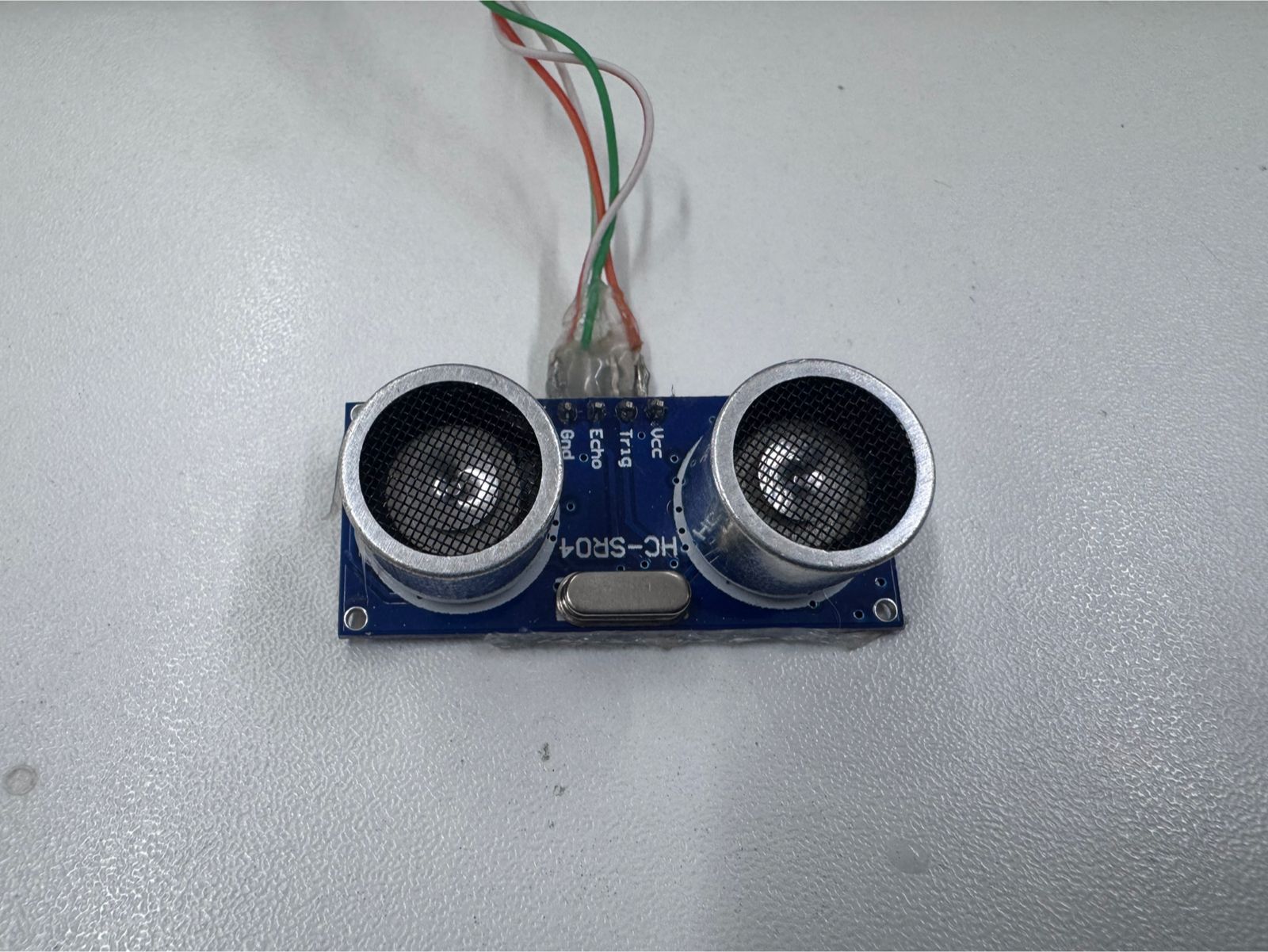
- HC-SR04 Ultrasonic Sensor
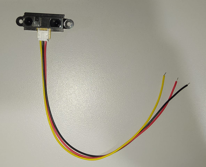
- Sharp 2Y0A21 F 3Z Infrared Proximity Sensor
- XIAO ESP32-C3
- Breadboard and jumper wires
- Digital Multimeter
- Fluke 117 Digital Multimeter
- Oscilloscope
🔄 Workflow – Testing HC-SR04 with XIAO ESP32-C3
Step-by-step process to probe analog and digital signals using a multimeter and an oscilloscope.
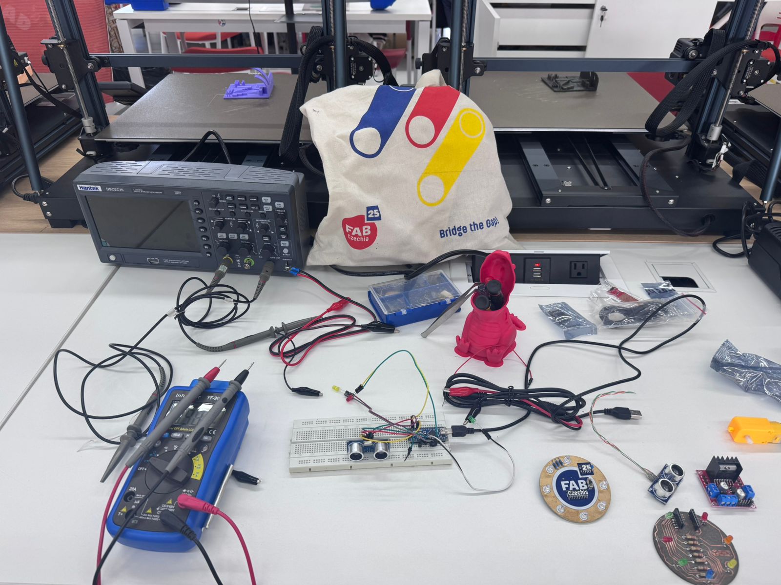
1️⃣ Component Preparation
Gather all required components: HC-SR04 sensor, XIAO ESP32-C3, breadboard, jumper wires, multimeter, and oscilloscope.
2️⃣ Circuit Assembly
Connect the sensor to the microcontroller:
- VCC → 5V / 3.3V
- GND → GND
- TRIG → Digital Output Pin
- ECHO → Digital Input Pin
Important: Use a voltage divider if required for the ECHO pin.
3️⃣ Code Upload
Upload a basic program to the XIAO ESP32-C3 to generate the TRIG pulse and read the ECHO signal.
💻 Final Code – HC-SR04 with XIAO ESP32-C3
/**
 * FabAcademy - Input Devices
 * Final Code: Ultrasonic Distance Measurement
 */

// Pin Configuration
const int TRIG_PIN = 4; // XIAO Pin D2
const int ECHO_PIN = 5; // XIAO Pin D3

void setup() {
  // Serial communication for data visualization
  Serial.begin(115200);

  // Initialize Pins
  pinMode(TRIG_PIN, OUTPUT);
  pinMode(ECHO_PIN, INPUT);

  Serial.println("System Online: HC-SR04 + ESP32-C3");
}

void loop() {
  long duration;
  float distanceCm;

  // Clear trigger to ensure a clean HIGH pulse
  digitalWrite(TRIG_PIN, LOW);
  delayMicroseconds(2);

  // Send 10 microsecond pulse
  digitalWrite(TRIG_PIN, HIGH);
  delayMicroseconds(10);
  digitalWrite(TRIG_PIN, LOW);

  // Measure the duration of the Echo pulse in microseconds
  // timeout set to 30000us (approx 5 meters)
  duration = pulseIn(ECHO_PIN, HIGH, 30000);

  // Physics: Distance = (Time * Speed of Sound) / 2
  // Speed of Sound = 0.0343 cm/us
  distanceCm = (duration * 0.0343) / 2;

  // Data Output
  if (duration == 0 || distanceCm > 400) {
    Serial.println("Status: Out of range / No echo");
  } else {
    Serial.print("Distance: ");
    Serial.print(distanceCm);
    Serial.println(" cm");
  }

  // Sampling rate control (10 readings per second)
  delay(100);
}
4️⃣ Multimeter Setup
Set the multimeter to measure DC voltage. Verify:
- Power supply voltage
- TRIG idle state
- Basic signal presence
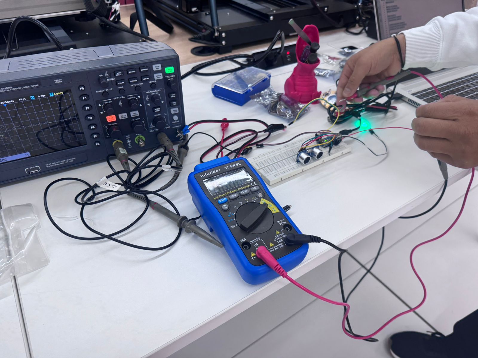
5️⃣ Multimeter Measurements
Measure voltage levels at different pins and confirm proper electrical connections.
Note that rapid signals may not be accurately displayed.
6️⃣ Oscilloscope Setup
Connect oscilloscope probes:
- Channel 1 → TRIG pin
- Channel 2 → ECHO pin
- GND → Common ground
7️⃣ Signal Observation
Observe the signals:
- TRIG: short square pulse (~10 µs)
- ECHO: variable pulse width depending on distance
8️⃣ Data Analysis
Measure the duration of the ECHO pulse using the oscilloscope and relate it to distance.
Circuit Connections
| HC-SR04 Pin | |
|---|---|
| VCC | 5V / 3.3V |
| GND | GND |
| TRIG | D2 (Output) |
| ECHO | D3 (Input) |
Note: Use a voltage divider for the ECHO pin if necessary.
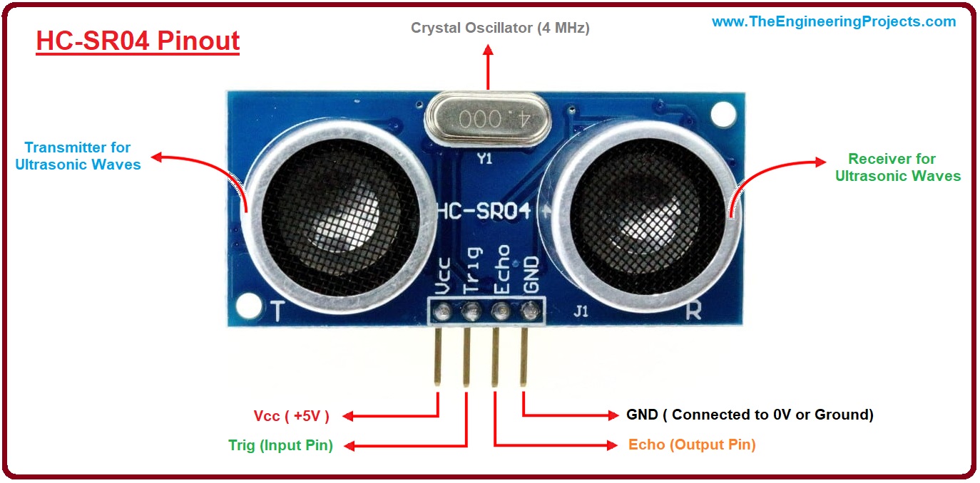
Working Principle
- Send a 10 µs pulse to TRIG
- Ultrasonic wave is emitted
- Signal reflects from object
- ECHO outputs HIGH pulse proportional to distance
Sharp 2Y0A21 F 3Z Infrared Proximity Sensor
The Sharp 2Y0A21 F 3Z is an infrared proximity sensor used to detect the distance between the sensor and an object. Unlike the HC-SR04, which works by emitting an ultrasonic sound pulse and measuring the echo time, this sensor uses infrared light. It includes an infrared emitter and a position-sensitive detector that receives the reflected light from the object.
Its output is analog, so the voltage changes depending on the distance of the object. When an object moves closer or farther away, the amount and angle of reflected infrared light changes, producing a different voltage level at the output pin. This makes it useful for applications where a continuous voltage variation is needed instead of a digital pulse.
Sensor Comparison: HC-SR04 vs Sharp 2Y0A21 F 3Z
Both sensors are proximity input devices, but they use different physical principles and provide different types of signals. The HC-SR04 provides a digital time-based signal, while the Sharp sensor provides an analog voltage that varies with distance.
| Feature | HC-SR04 Ultrasonic Sensor | Sharp 2Y0A21 F 3Z Infrared Sensor |
|---|---|---|
| Detection method | Uses ultrasonic sound waves and measures the echo return time. | Uses infrared light reflection and measures the returned light position. |
| Output signal | Digital pulse on the ECHO pin. | Analog voltage on the output pin. |
| Distance reading | Calculated from pulse duration using the speed of sound. | Estimated from the output voltage variation. |
| Measurement behavior | The pulse width increases or decreases depending on distance. | The voltage level changes as the object moves closer or farther away. |
| Instrument observation | Best observed with an oscilloscope because the signal is a fast digital pulse. | Can be observed with a multimeter and oscilloscope because the output is analog. |
| Main advantage | Good for direct distance calculation using timing. | Simple analog output that can be read directly by an analog input pin. |
| Main limitation | Requires timing measurement and proper signal level handling. | The voltage-distance relationship is not linear and depends on reflection conditions. |
Measurements with Multimeter
- VCC → GND: ~5V / 3.3V
- TRIG idle: ~0V
- ECHO: fluctuating voltage
The multimeter is useful for static measurements but cannot accurately detect fast signals.
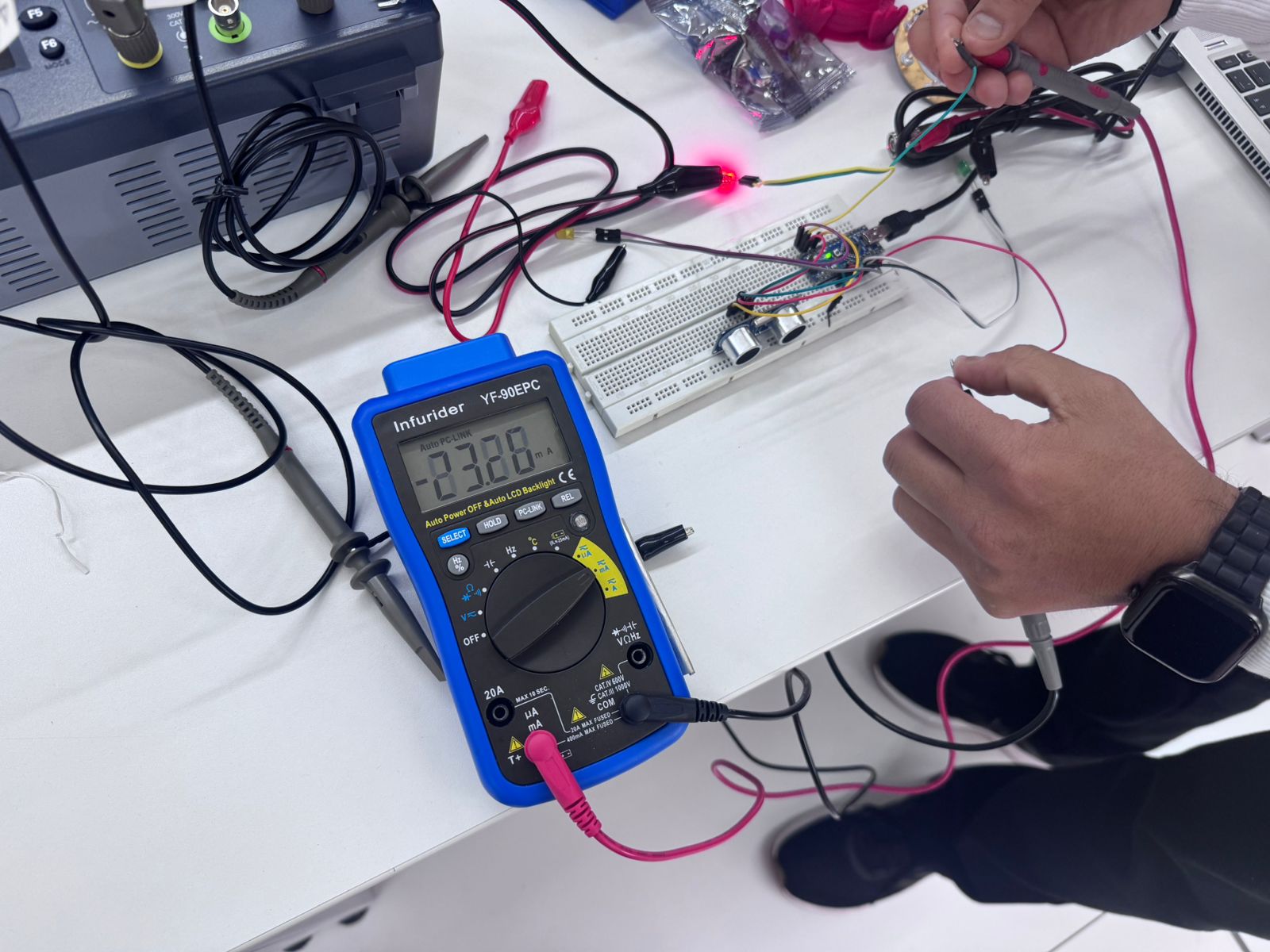
Analog Voltage Measurement with Multimeter
For the Sharp infrared proximity sensor, the voltage was measured directly at the analog output pin A0. The sensor was powered and connected on the breadboard, and the Fluke 117 multimeter was connected to the output pin and ground to observe the DC voltage level.
During the test, a hand was moved closer to and farther away from the sensor. As the distance changed, the voltage at the output also changed. This confirms that the Sharp sensor behaves as an analog input device, where the output voltage varies according to the detected distance.
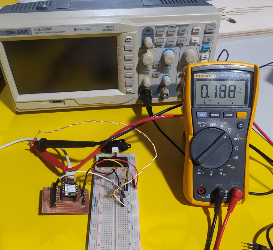
In the video, the output voltage changes as the distance between the sensor and the hand is modified. This demonstrates the analog response of the sensor in real time.
Analog Signal Observation with Oscilloscope
The Sharp sensor output was also tested using the oscilloscope. The oscilloscope probe was connected to the analog output of the sensor, while the ground clip was connected to the common ground of the circuit. Channel 1 was used to visualize the voltage variation in real time.
Since the Sharp sensor provides an analog output, the oscilloscope does not show a pulse-width signal like the HC-SR04. Instead, it shows a voltage level that changes as the distance between the object and the sensor changes.
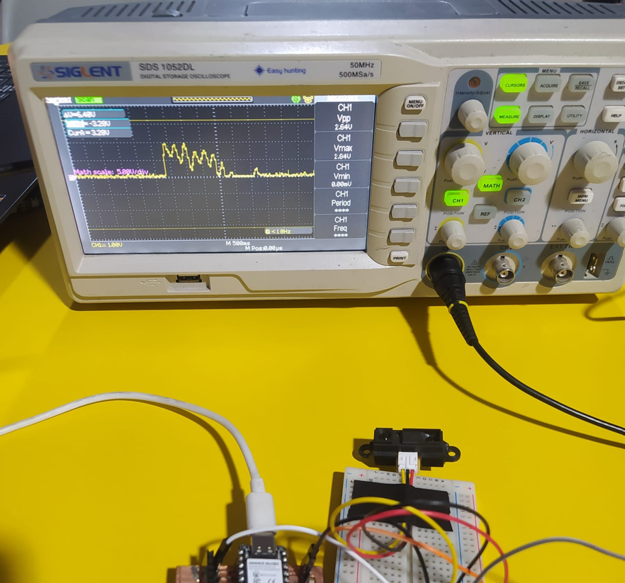
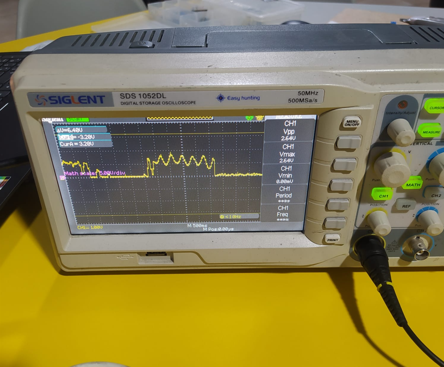
In this test, the distance was modified while observing Channel 1 on the oscilloscope. The waveform changed its voltage level according to the movement of the object in front of the sensor, confirming the analog behavior previously observed with the multimeter.
Measurements with Oscilloscope
- TRIG: Square pulse (~10 µs)
- ECHO: Variable pulse width depending on distance
The oscilloscope allows real-time visualization of signals and precise timing analysis.
Distance Calculation
d = (t × v) / 2
Where:
d = distance
t = time of pulse
v = speed of sound (~343 m/s)
Results
- Stable TRIG digital signal observed
- ECHO pulse width varies with distance
- Accurate timing only visible with oscilloscope
- The Sharp infrared sensor produced an analog voltage variation at its output pin
- The multimeter allowed us to observe the voltage change when the distance was modified
- The oscilloscope showed the real-time variation of the analog output signal
- The Sharp infrared sensor has a single analog output pin, where the voltage changes according to the detected distance.
- With the multimeter, it was not possible to determine an exact voltage value because the distance variation produced rapid changes in the output reading.
- Using the oscilloscope, the voltage variation on the output signal was observed more clearly, including small peaks caused by changes in distance, which made the signal not completely clean or stable.
Comparison
| Tool | Advantage | Limitation |
|---|---|---|
| Multimeter | Easy voltage measurement | Cannot detect fast signals |
| Oscilloscope | Real-time waveform analysis | Requires setup |