WEEK 14 - Molding and Casting
Group Assignment
The group assignment for Week 14 focused on understanding the complete molding and casting workflow from a material, safety, and process perspective. As a team, we analyzed different molding and casting materials, reviewed their Safety Data Sheets (SDS), and identified the correct handling procedures, personal protective equipment, curing conditions, and possible risks associated with each material.
This group work was important because molding and casting processes involve chemical materials that require controlled preparation, accurate mixing, proper ventilation, and safe demolding practices.
Individual Assignment: CNC Mold, Silicone Mold and Resin Casting
The objective of the individual assignment was to design and fabricate a mold using a digital fabrication process, produce a flexible mold from it, and finally cast a physical object. For this assignment, I developed a cat face mold based on a digital model downloaded from Printables. The original model was used as a starting reference and was later adapted to create a manufacturable mold for the molding and casting process.
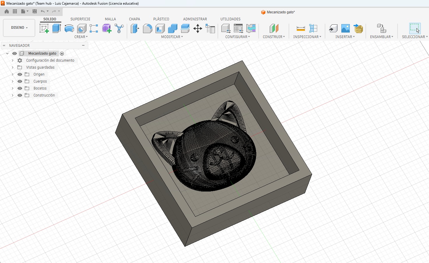
The digital preparation of the model was carried out in Autodesk Fusion 360. The CAM process was developed in Aspire, where I defined the stock dimensions, material thickness, machining origin, cutting strategy, toolpath preview, and CNC machining parameters.
Once the CNC machining process was completed, the mold surface showed visible toolpath marks. To improve the quality of the final casting, I manually sanded and sealed the mold before pouring silicone.
For the final object, I used EPOX-21 epoxy resin. The cast was left to cure for 72 hours before demolding to ensure complete polymerization and dimensional stability.
1. Individual Workflow
- Reviewed the group assignment results, including material behavior, SDS information, and safety recommendations.
- Selected the cat face model from Printables as the base geometry for the individual mold.
- Prepared and adapted the 3D model in Fusion 360 to create a positive master mold.
- Prepared the CAM process in Aspire by defining stock size, origin, toolpath strategy, and machining parameters.
- Generated and saved the CAM files for CNC Router machining.
- Machined the mold using a CNC Router and a 6 mm End Mill.
- Sanded and sealed the CNC mold to improve the surface finish.
- Prepared and poured the silicone into the CNC-machined master mold.
- Demolded the flexible silicone mold.
- Prepared, poured, cured, and demolded the final EPOX-21 resin casting.
2. Cat Design and Digital Preparation for CNC Machining
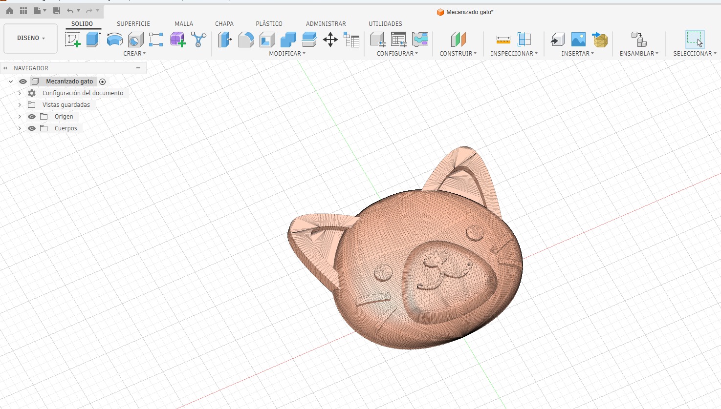
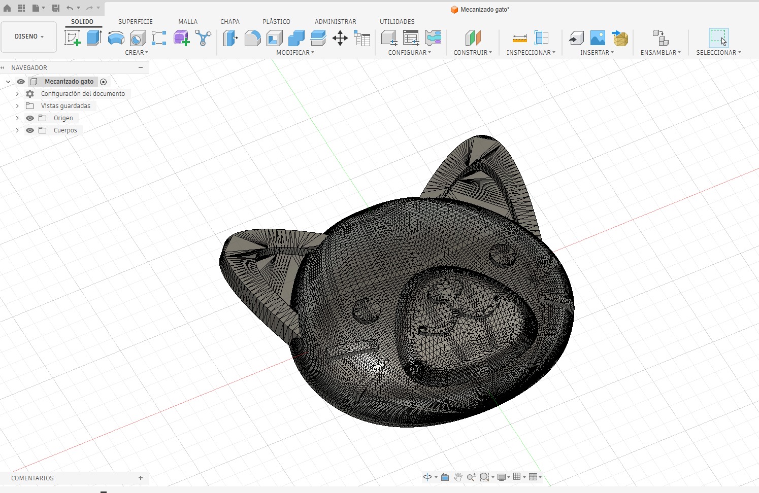
The individual mold was developed from a kitten face relief model. The original geometry was downloaded from Printables: Cat Face model. After downloading the file, I imported and prepared it in Autodesk Fusion 360.
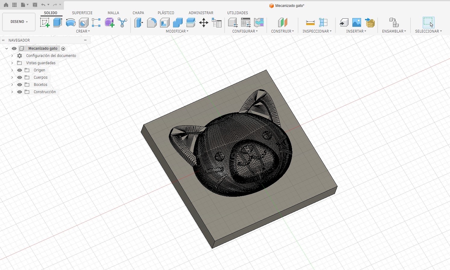
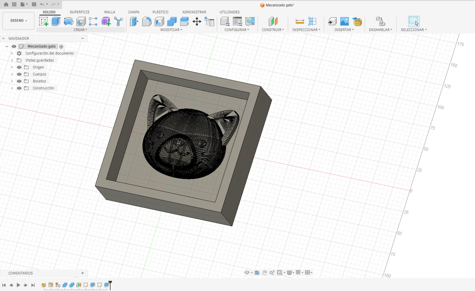
The original decorative relief was adapted into a functional mold master by adding a rectangular base, surrounding walls, and enough containment area for silicone pouring.
| Design Step | Description |
|---|---|
| Original model reference | The kitten face model was downloaded from Printables. |
| Software used | Autodesk Fusion 360 for design preparation and Aspire for CAM. |
| Base creation | The cat relief was positioned on a rectangular base to create a machinable master. |
| Containment walls | Walls were added around the relief to define the mold limits and hold the silicone. |
Design Evidence in Fusion 360
3. CAM Process and Milling Strategy
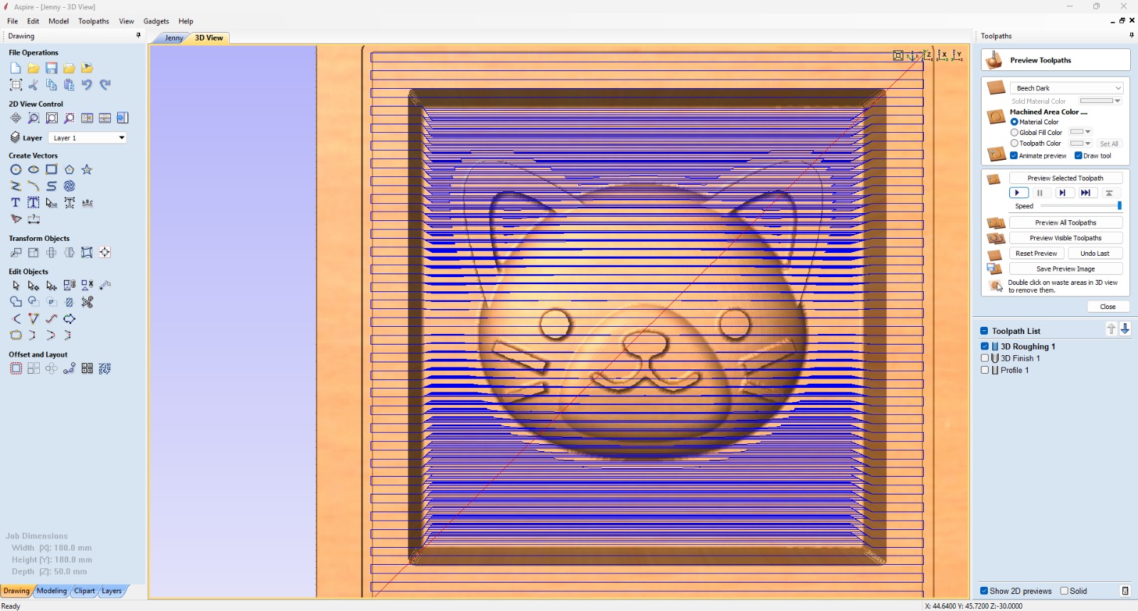
After finishing the digital design in Fusion 360, I used Aspire to prepare the CAM operations and generate the toolpaths for the CNC Router. In Aspire, I defined the stock dimensions, material thickness, machining origin, tool selection, roughing operation, finishing operation, and toolpath preview.
A 6 mm End Mill was used to machine the mold. The strategy removed the material progressively and created the mold cavity, border, and cat face relief.
CAM Evidence 1: Toolpath Trajectory
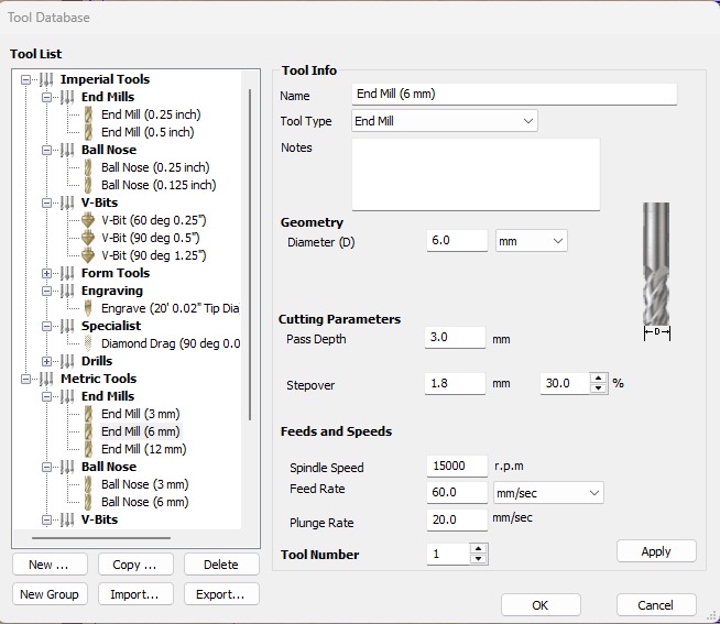
CAM Evidence 2: Tool Setup and Cutting Parameters
CAM Files Used During Fabrication
The CAM files used during the fabrication process are published in the archive folder. These files contain the Aspire machining setup, tool selection, stock configuration, roughing toolpath, finishing toolpath, and cutting parameters.
CNC Tool and Machining Parameters
| Parameter | Value Used | Unit | Purpose |
|---|---|---|---|
| CAM software | Aspire | - | Used to prepare toolpaths and CAM setup. |
| Tool name | End Mill 6 mm | - | Main cutting tool selected for machining. |
| Tool diameter | 6.0 | mm | Defines the minimum internal radius and machining detail. |
| Pass depth | 3.0 | mm | Maximum cutting depth removed in each pass. |
| Stepover | 1.8 | mm | Distance between adjacent toolpath passes. |
| Stepover percentage | 30 | % | Controls overlap between passes and surface finish. |
| Spindle speed | 15000 | rpm | Rotational speed of the CNC spindle. |
| Feed rate | 60 | mm/sec | Horizontal cutting speed. |
| Feed rate equivalent | 3600 | mm/min | Converted feed rate value. |
| Plunge rate | 20 | mm/sec | Vertical speed when the tool enters the material. |
| Plunge rate equivalent | 1200 | mm/min | Converted plunge rate value. |
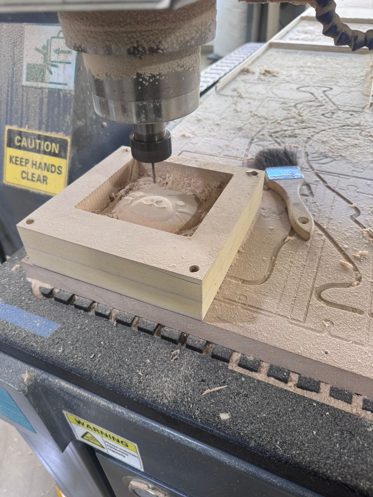
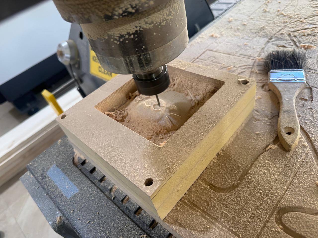
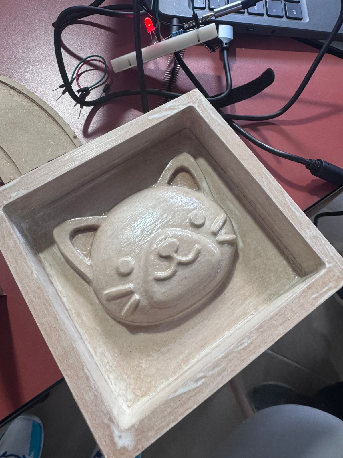
4. CNC Milling Process
The cat mold was fabricated using a CNC Router. The machine followed the CAM files generated in Aspire and removed material layer by layer until the face, ears, eyes, nose, whiskers, and surrounding cavity were created.
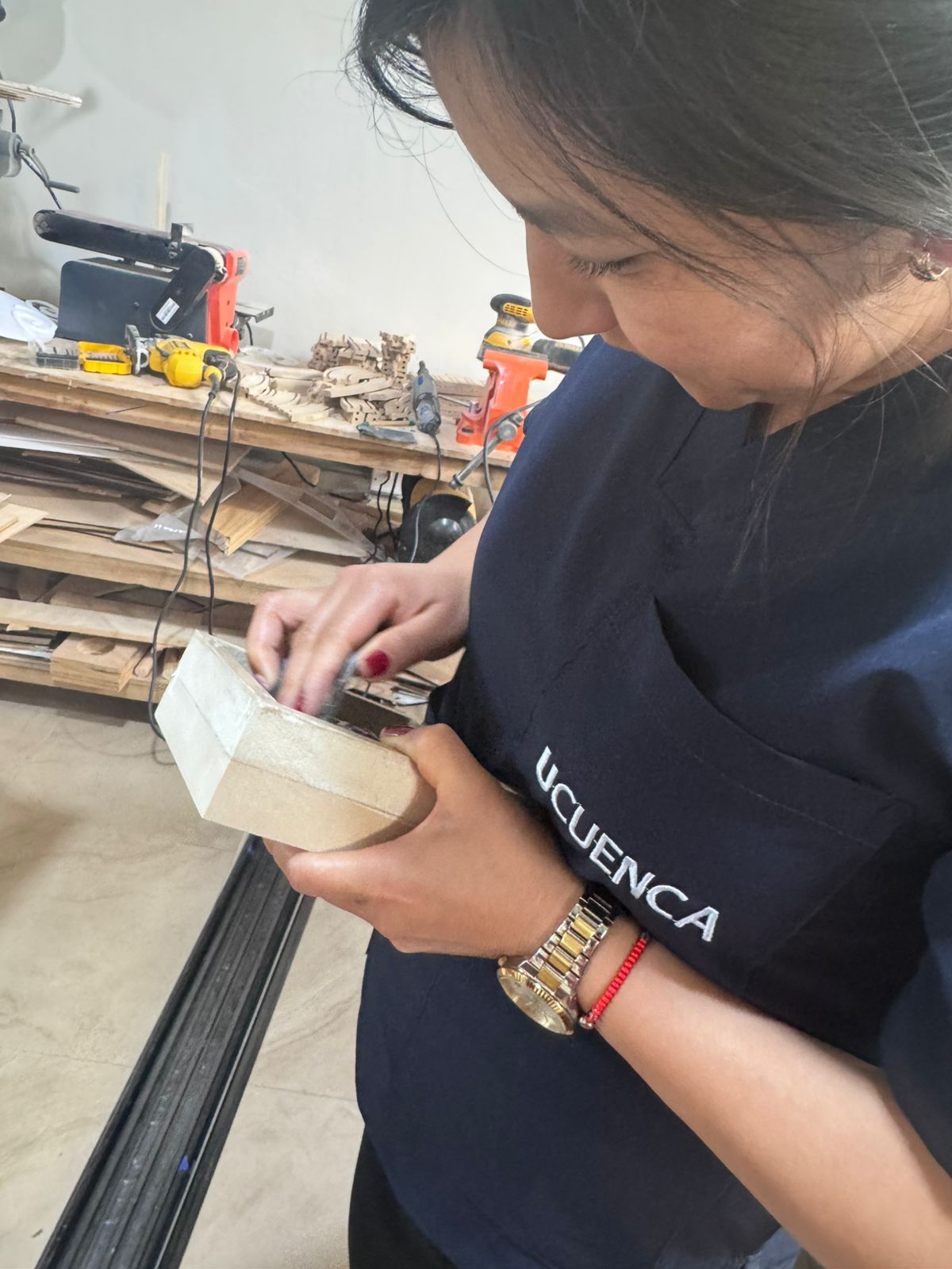
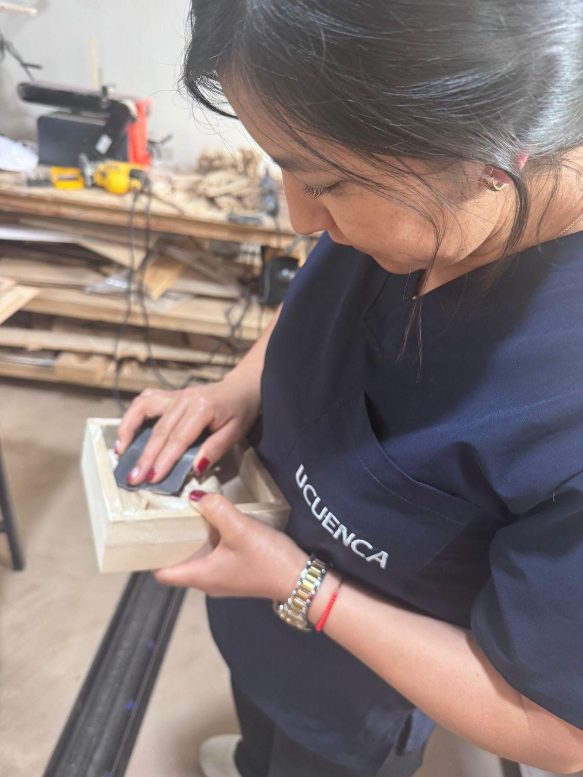
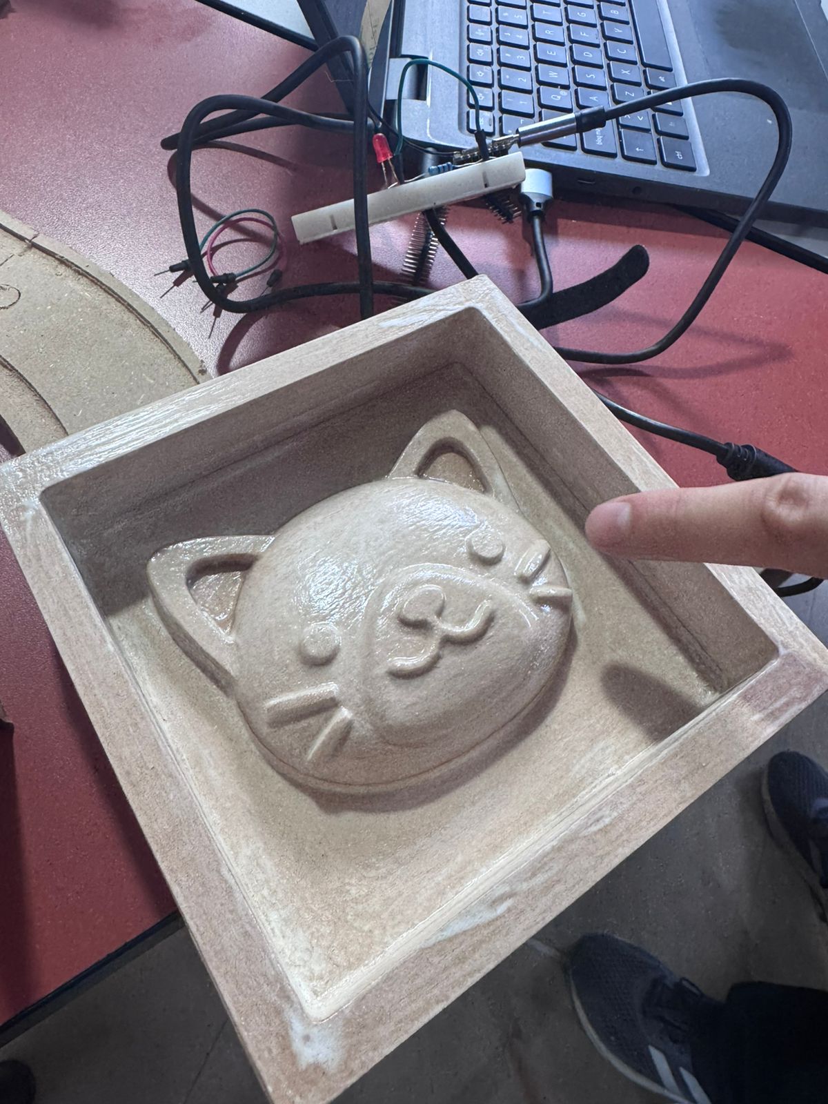
5. Sanding and Surface Correction
After milling, the mold was corrected by sanding. This step was necessary to reduce the toolpath marks and obtain a smoother surface finish.
6. Mold Sealing
The milled mold was sealed before pouring silicone. Sealing reduced the porosity of the wood-based material, improved the surface finish, and helped the silicone release more easily after curing.
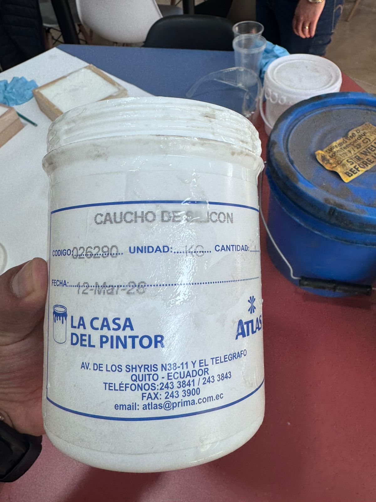
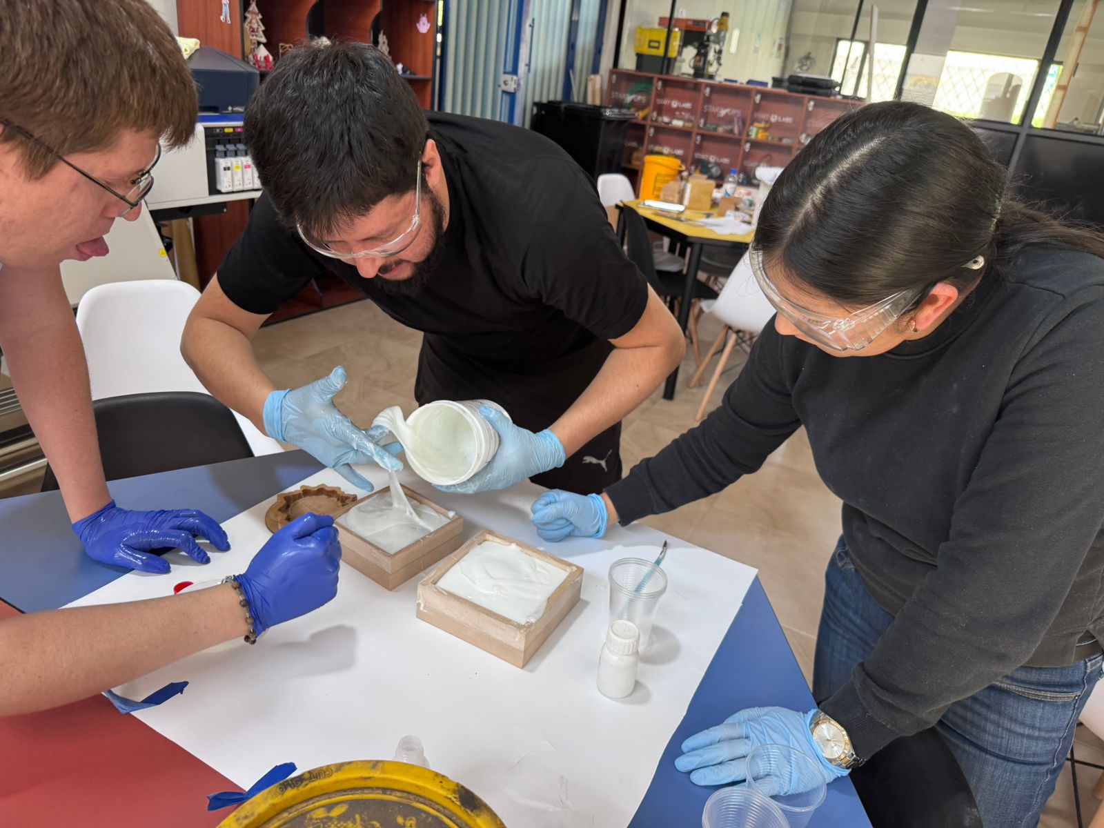
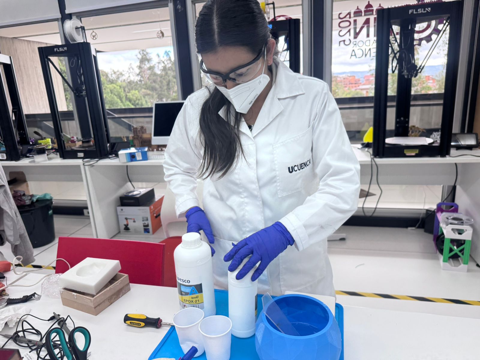
7. Silicone Preparation
Safety equipment was used during the process, including gloves, safety glasses and a mask. The silicone material was mixed carefully to obtain a homogeneous mixture and avoid uncured areas.
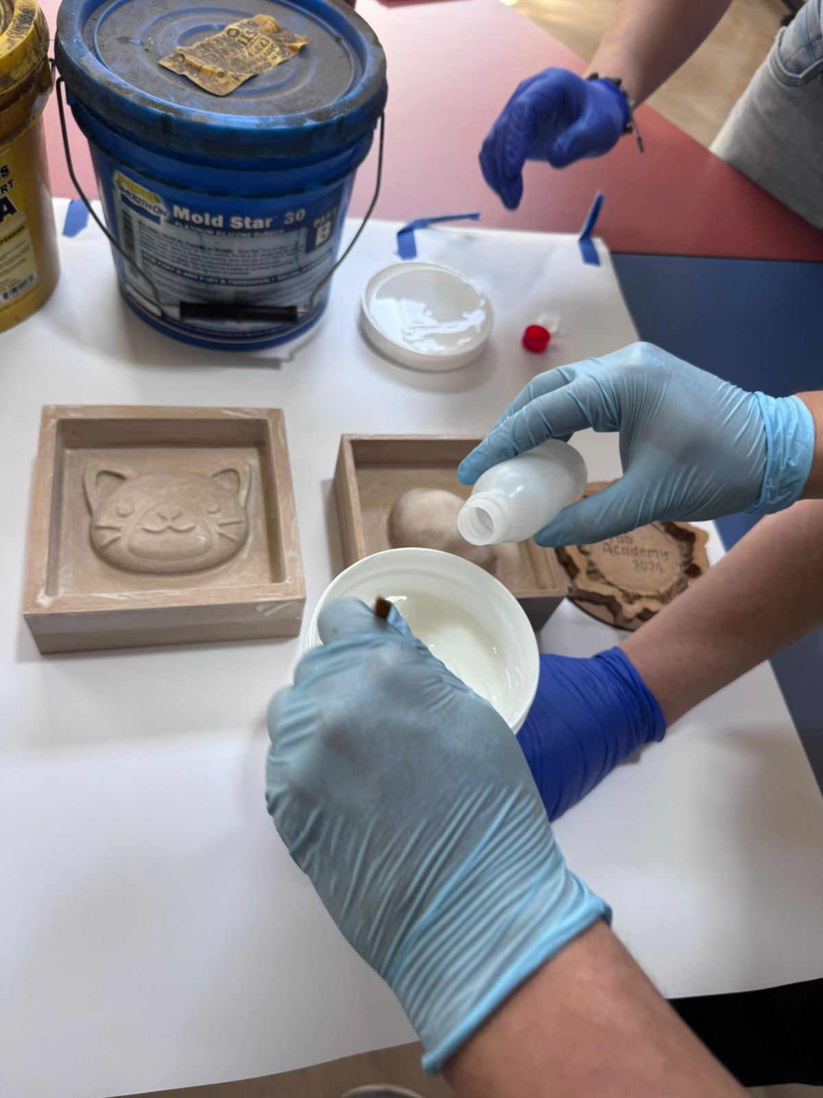
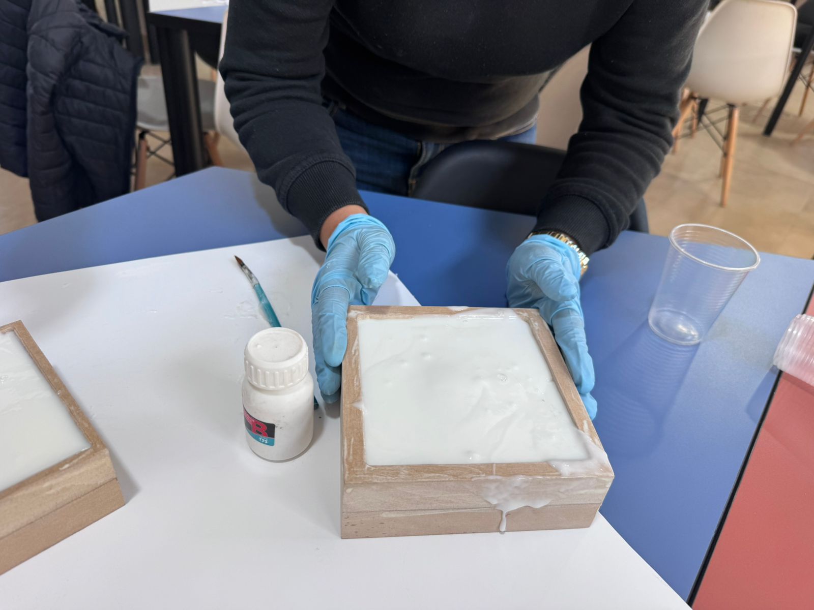
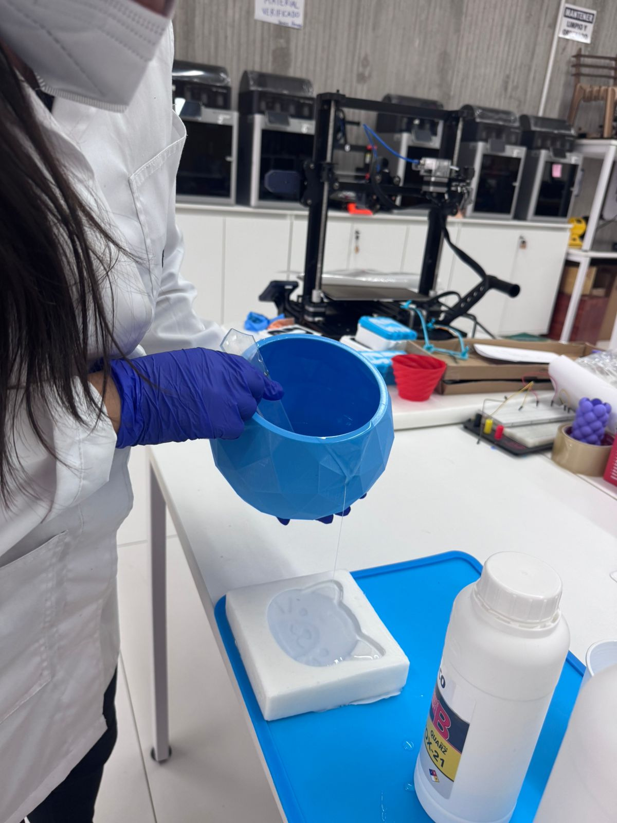
8. Pouring Silicone into the CNC Mold
The silicone mixture was poured slowly into the CNC-machined mold. Pouring from one side allowed the material to flow naturally across the surface and helped reduce trapped air.
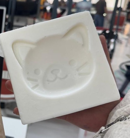
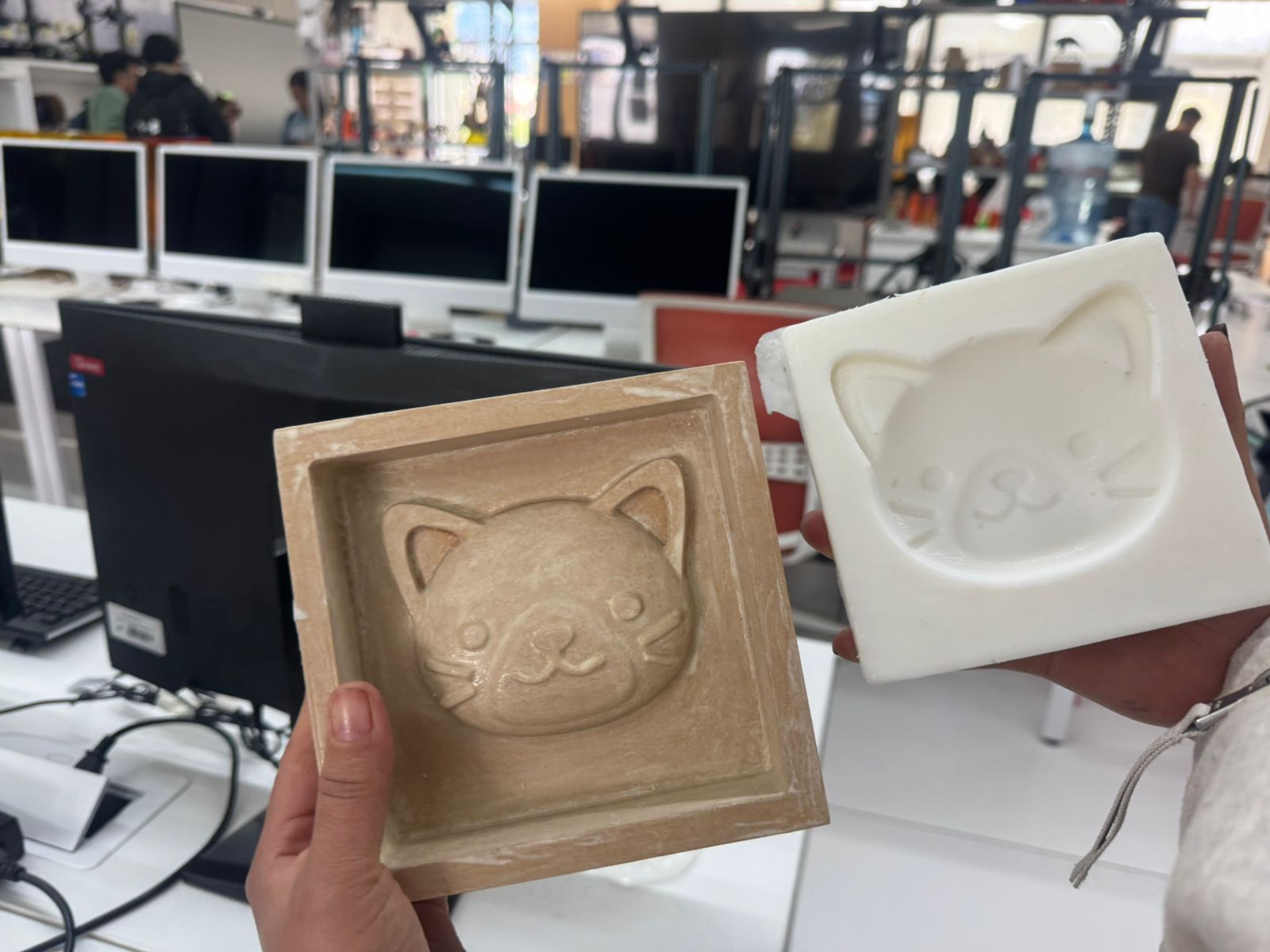
9. Silicone Mold Demolding
After curing, the silicone mold was carefully removed from the CNC master. The flexible mold captured the cat face details and was ready to be used for resin casting.
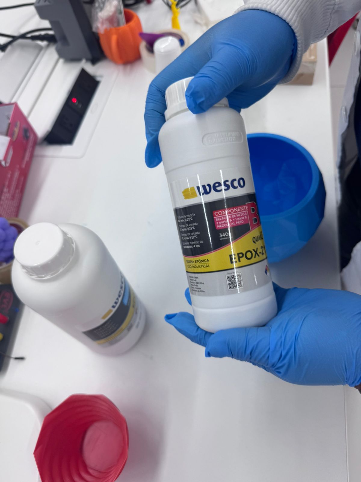
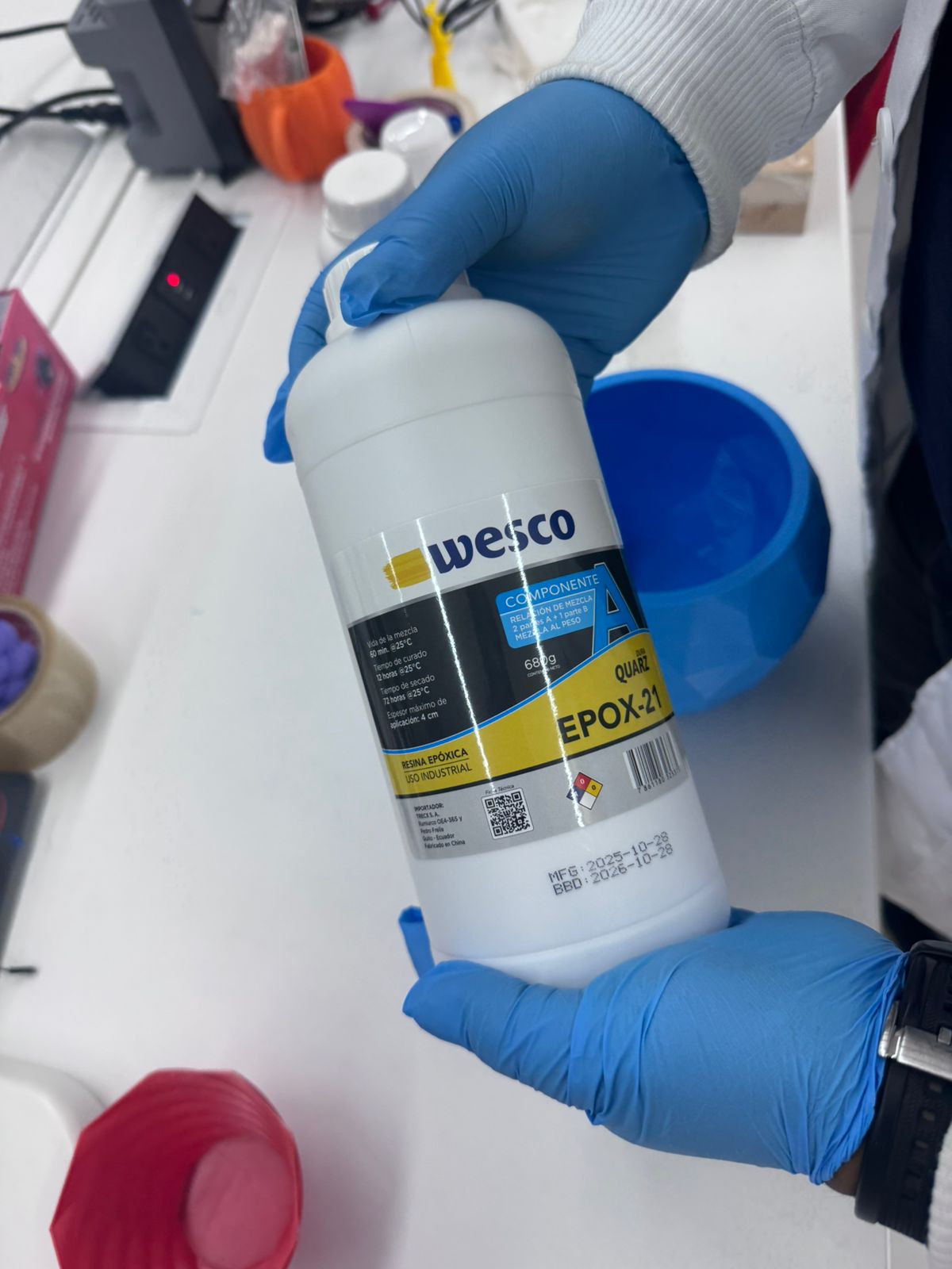
10. EPOX-21 Resin Preparation
For the final casting stage I used EPOX-21 epoxy resin. The material included component A and component B. The resin was mixed slowly to avoid bubbles and to obtain a uniform mixture before pouring it into the silicone mold.
| Technical Item | EPOX-21 Resin Preparation |
|---|---|
| Material type | Two-component clear epoxy casting resin: component A and component B. |
| Application | Final resin casting inside the flexible silicone mold. |
| Mixing ratio | 4 parts of component A + 1 part of component B. |
| Curing time used | 72 hours before demolding. |
| Safety equipment | Gloves, safety glasses, long sleeves and good ventilation. |
Visible Technical Sheet: DURA QUARZ Epoxy Resin
11. Resin Casting into the Silicone Mold
Once the resin was mixed, it was poured into the silicone mold. The resin was added slowly so that it could fill the detailed areas of the mold and reduce the formation of bubbles.
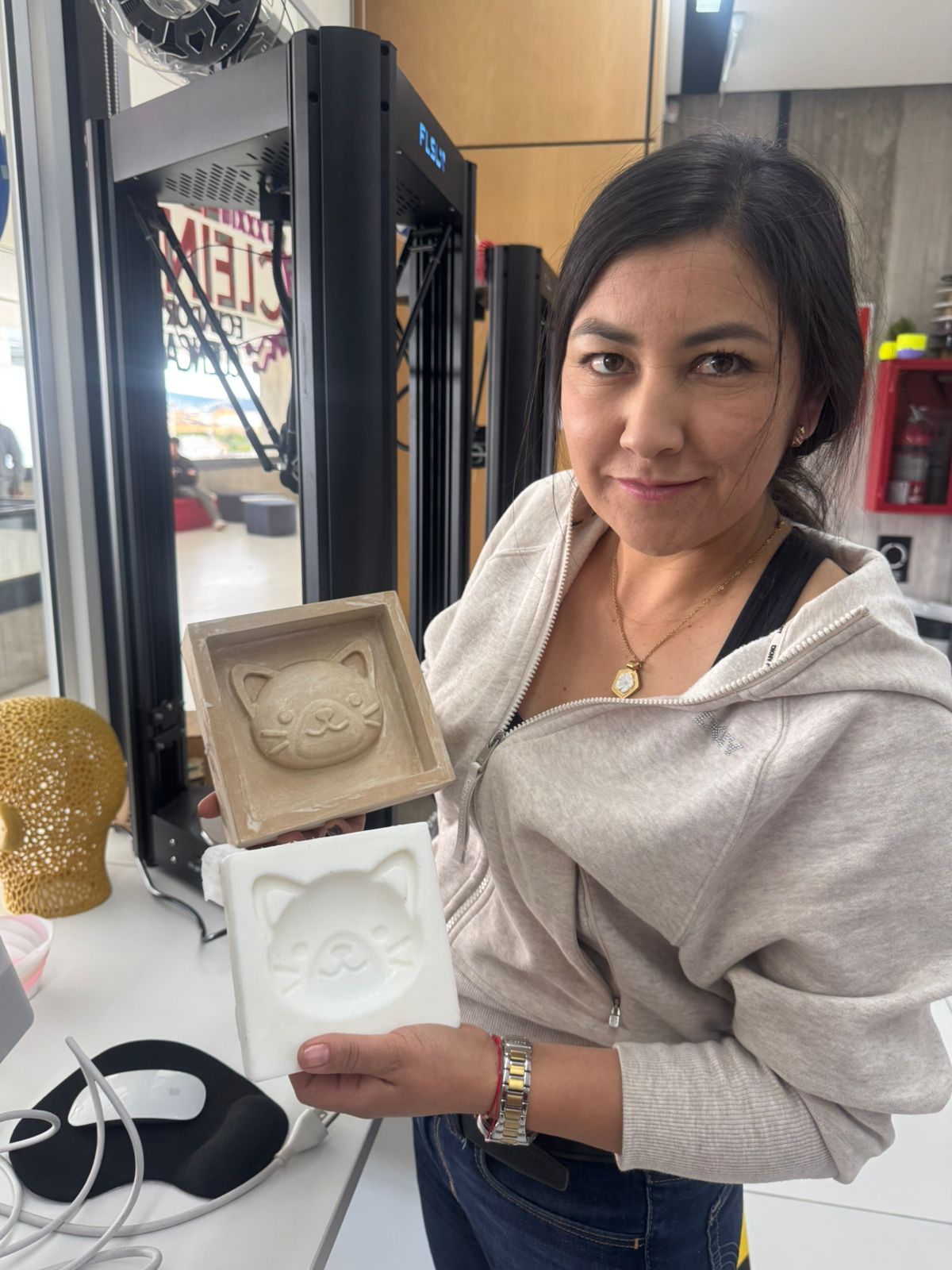
12. Hero Shot - Final Resin Casting Result
This hero shot presents the complete result of the molding and casting workflow. Starting from a digitally prepared cat relief, a CNC-machined master mold was fabricated, improved through sanding and sealing, used to produce a flexible silicone mold, and finally cast with EPOX-21 epoxy resin.
13. Problems and Solutions
| Problem | Solution |
|---|---|
| Visible tool marks after CNC milling | The mold was sanded manually to improve the surface finish before making the silicone mold. |
| Limited detail due to the 6 mm End Mill | The mold was designed with manufacturable relief features and corrected after machining. |
| Porosity of the milled material | The mold was sealed before pouring silicone to improve release and reduce surface defects. |
| Risk of bubbles in silicone and resin | The materials were mixed slowly and poured carefully from one side of the mold. |
| Risk of premature demolding | The resin was left to cure for 72 hours before demolding. |
14. Download Files
The original kitten relief reference was downloaded from Printables and later modified in Fusion 360 for the molding and casting assignment. The final Fusion 360 file documents the adapted mold design used for CNC Router machining.
To address the evaluation feedback, I also included the CAM files used during fabrication. These files document the Aspire setup, roughing operation, finishing operation, selected tool, trajectory, and CNC preparation used to fabricate the mold.
| File | Format | Purpose | Download / Link |
|---|---|---|---|
| Original Cat Face Model | External reference | Original kitten relief used as the starting geometry. | Open Printables Model |
| Mecanizadogato.f3d | Fusion 360 file | Editable mold design file with cat relief, base, walls, and silicone containment area. | Download F3D File |
| gato.crv3d | Aspire project file | Editable Aspire file used to prepare the mold machining workflow. | Download CRV3D File |
| 3D finish pulido | CNC finishing toolpath | Finishing toolpath used to improve the surface detail and final relief quality. | Download 3D Finish File |
| 3D Roughing mecanizado | CNC roughing toolpath | Roughing toolpath used to remove the main material before the finishing operation. | Download 3D Roughing File |
| FichaTecnicaDuraQuarz.pdf | Technical sheet used for epoxy resin preparation and safety reference. | Open Technical Sheet |
15. Fab Academy Checklist
- Linked to the group assignment page and reflected on my individual page what I learned
- Reviewed the safety data sheets for each molding and casting material
- Documented how I designed and created my 3D mold, including Fusion 360 preparation, Aspire CAM setup, CNC Router machining and the 6 mm End Mill
- Documented detailed machining parameters, including spindle speed, feed rate, plunge rate, pass depth and stepover
- Added CAM evidence with the full-width toolpath trajectory image and the Aspire tool database image
- Published the CAM files used during fabrication as downloadable archive files
- Ensured the mold has a smooth surface finish through sanding and sealing
- Shown how I safely made the mold and cast the parts
- Described problems and how I fixed them
- Included design files and hero shot of the mold and final object
16. Final Reflection
This assignment allowed me to understand how molding and casting connects digital design, subtractive manufacturing, material preparation, and final part production. Through the group assignment, I learned the importance of reviewing Safety Data Sheets, selecting appropriate materials, and following safe working procedures when using silicone and epoxy resin systems.
In the individual assignment, I applied this knowledge by designing and manufacturing a cat face mold. I prepared the model in Fusion 360, generated the CAM setup in Aspire, machined the master mold on a CNC Router using a 6 mm End Mill, improved the surface through sanding and sealing, produced a silicone mold, and finally cast the piece using EPOX-21 epoxy resin.
I also learned that CAM documentation is essential for reproducibility. Recording the toolpath trajectory, selected tool, feed rate, plunge rate, spindle speed, pass depth, stepover, and CAM files makes it possible for another person to understand how the mold was actually machined.