WEEK 11 – Networking and Communications
Assignment Documentation
XIAO ESP32-C6 + Blynk Cloud LED Control
This assignment focused on understanding how an embedded system can communicate through a wireless network. I used a XIAO ESP32-C6, WiFi, and Blynk Cloud to control a physical LED from a virtual button in a mobile or web dashboard.
The purpose of this practice was not only to turn an LED on and off, but also to understand the complete communication flow between the user interface, the cloud platform, the WiFi network, and the microcontroller. This workflow is important for IoT applications because it allows a physical device to be controlled remotely.
In this case, the Blynk virtual button sends a value to the XIAO ESP32-C6. The board receives that value, changes the state of the physical LED, and also sends a message back to the Blynk dashboard.
1. Checklist
- ✅ Linked to the group assignment page.
- ✅ Documented the networking and communication process.
- ✅ Explained the programming workflow used with Arduino IDE.
- ✅ Used a wireless node based on the XIAO ESP32-C6.
- ✅ Used WiFi communication with Blynk Cloud.
- ✅ Controlled a physical output device from a virtual interface.
- ✅ Explained the difference between physical pins and virtual pins.
- ✅ Included source code.
- ✅ Included only the most important visual evidence.
- ✅ Included problems, solutions, and final reflection.
2. Group Assignment
Communication Between Boards
For the group assignment, we explored communication between different embedded boards. The objective was to understand how microcontrollers can exchange information using networking tools and communication channels.
My individual assignment is connected to the group work because it uses the same principle of networked communication, but focuses on one board connected to a cloud dashboard. Instead of communicating only between boards, this test connects a physical output to an IoT interface.
Group Assignment:
Open Group Assignment3. What is Networking and Communications?
Networking and communications in embedded systems refers to the ability of a device to send and receive information through a communication protocol. This can happen through wires, such as UART, I2C, SPI, or USB, or wirelessly through technologies such as WiFi, Bluetooth, LoRa, or cellular networks.
For this assignment, I used WiFi because the XIAO ESP32-C6 has integrated wireless connectivity. WiFi allowed the board to connect to the internet and communicate with Blynk Cloud. This makes the board work as an IoT node, capable of receiving commands from a dashboard and controlling a local output.
| Protocol / Technology | Type | Use | Use in this Assignment |
|---|---|---|---|
| UART / Serial | Wired | Debugging and board-to-computer communication | Used with the Serial Monitor to verify the program status. |
| I2C | Wired | Connecting sensors and modules with two wires | Not used, but useful for future sensor nodes. |
| SPI | Wired | Fast communication with displays, memory, or modules | Not used in this LED control test. |
| WiFi | Wireless | Internet connection and IoT dashboards | Main communication technology used to connect the board to Blynk. |
| Blynk Virtual Pins | Cloud communication | Exchange data between dashboard widgets and hardware | V1 was used for the virtual button and V2 for the message label. |
4. Board and Components Used
XIAO ESP32-C6 Board
The main board used in this assignment was the XIAO ESP32-C6. This board is small, easy to integrate into compact projects, and includes WiFi connectivity. This made it suitable for testing a wireless communication workflow with Blynk Cloud.
The LED was used as a physical output device. When the virtual button in Blynk is activated, the ESP32-C6 receives the value and changes the LED state.
| Component | Function |
|---|---|
| XIAO ESP32-C6 | Main microcontroller with WiFi communication. |
| LED | Physical output controlled from Blynk. |
| 220 Ω resistor | Protects the LED from excessive current. |
| WiFi network | Allows connection between the board and Blynk Cloud. |
| Blynk dashboard | Interface used to control and monitor the LED state. |
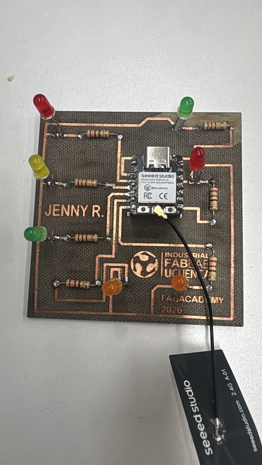
XIAO ESP32-C6 used as the wireless node for this assignment.
5. Blynk Cloud Configuration
Blynk Cloud was used as the IoT platform for this assignment. The first step was to create a template and a device. This device generates an authentication token, which is necessary for the microcontroller to connect to the correct project in Blynk.
The authentication token works like a digital identity for the board. If the token is incorrect, the board may connect to WiFi, but it will not communicate with the Blynk dashboard.
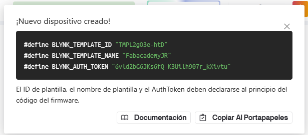
Blynk device created for the XIAO ESP32-C6 communication test.
6. Datastream Configuration
Virtual Pins
In Blynk, a datastream is a communication channel between the dashboard and the hardware. For this assignment, I used two virtual pins:
- V1: Virtual button used to turn the LED on or off.
- V2: Label or text widget used to show a message when the LED is on.
It is important to understand that virtual pins are not the same as physical pins. A physical pin, such as D5, is connected to real hardware. A virtual pin, such as V1 or V2, only exists inside Blynk and is used to send or receive data through the cloud.
| Blynk Element | Virtual Pin | Function |
|---|---|---|
| Button | V1 | Sends 1 when ON and 0 when OFF. |
| Label / Text | V2 | Displays the message sent by the ESP32-C6. |
Datastream configuration using virtual pins for button control and message display.
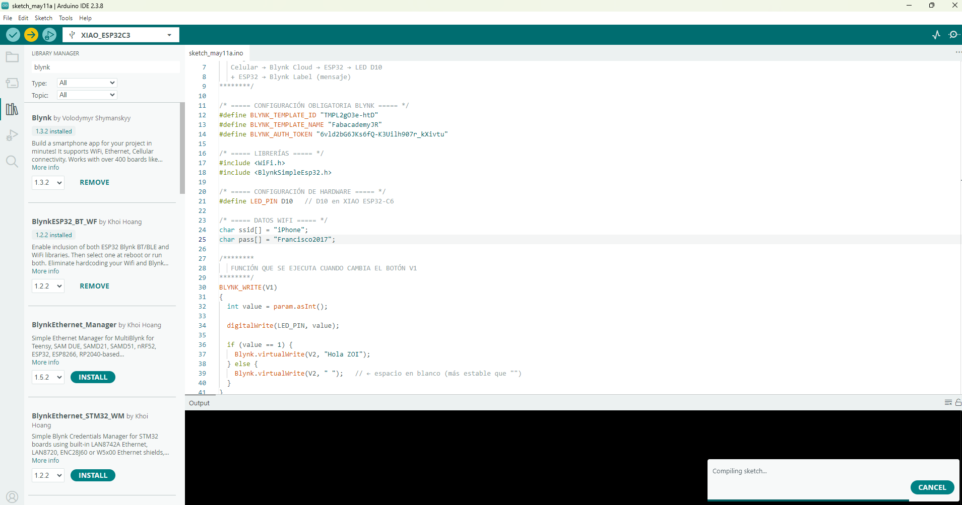
7. Arduino IDE Code
The Arduino code connects the XIAO ESP32-C6 to WiFi and then to Blynk Cloud. The code includes the Blynk template information, the authentication token, the WiFi credentials, and the physical LED pin.
One error I found during programming was caused by special characters in comments. The arrow symbol was interpreted incorrectly by the compiler because the comment block was not opened correctly. I solved this by using a proper block comment and replacing special arrows with normal text.
/********
   XIAO ESP32-C6 + Blynk
   Control of a physical LED from a virtual button (V1)
   Dynamic message in Blynk using virtual pin V2

   Flow:
   Cellphone - Blynk Cloud - ESP32 - LED
   ESP32 - Blynk Label
********/

/* ===== REQUIRED BLYNK CONFIGURATION ===== */
#define BLYNK_TEMPLATE_ID "TMPL2gO3e-htD"
#define BLYNK_TEMPLATE_NAME "FabacademyJR"
#define BLYNK_AUTH_TOKEN "YOUR_BLYNK_AUTH_TOKEN"

/* ===== LIBRARIES ===== */
#include <WiFi.h>
#include <BlynkSimpleEsp32.h>

/* ===== HARDWARE CONFIGURATION ===== */
#define LED_PIN D5

/* ===== WIFI DATA ===== */
char ssid[] = "YOUR_WIFI_NAME";
char pass[] = "YOUR_WIFI_PASSWORD";

/* ===== FUNCTION EXECUTED WHEN BUTTON V1 CHANGES ===== */
BLYNK_WRITE(V1)
{
  int value = param.asInt();

  digitalWrite(LED_PIN, value);

  if (value == 1) {
    Blynk.virtualWrite(V2, "Hola ZOI");
  } else {
    Blynk.virtualWrite(V2, " ");
  }
}

/* ===== SETUP ===== */
void setup()
{
  Serial.begin(115200);
  delay(1000);

  Serial.println("Starting system...");

  pinMode(LED_PIN, OUTPUT);
  digitalWrite(LED_PIN, LOW);

  Serial.println("Connecting to WiFi and Blynk...");
  Blynk.begin(BLYNK_AUTH_TOKEN, ssid, pass);

  Serial.println("System ready.");
}

/* ===== LOOP ===== */
void loop()
{
  Blynk.run();
}
For safety and documentation clarity, the real WiFi password and Blynk token should not be published in the
final website. In the public version, they should be replaced with placeholders such as
YOUR_WIFI_PASSWORD and YOUR_BLYNK_AUTH_TOKEN.
Downloadable file:
Download Arduino Code8. Code Upload and Serial Monitor
Programming Process
- Open Arduino IDE.
- Install or verify the ESP32 board package.
- Select the XIAO ESP32-C6 board or the compatible ESP32-C6 option.
- Select the correct USB port.
- Install the Blynk library if it is not already installed.
- Paste the corrected code.
- Replace the WiFi name, WiFi password, and Blynk token.
- Upload the code to the board.
- Open the Serial Monitor at 115200 baud.
- Verify that the board connects to WiFi and Blynk.
Arduino IDE and Serial Monitor used to verify the WiFi and Blynk connection.
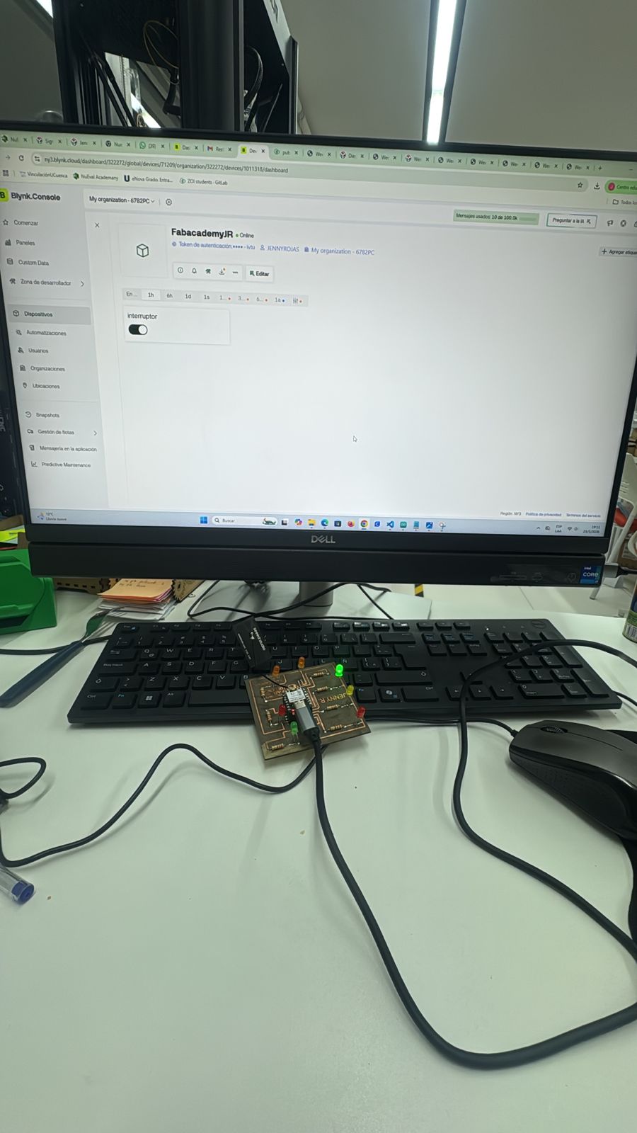
9. Functional Test
The final test confirmed that the communication system worked correctly. When the virtual button in Blynk was turned ON, the ESP32-C6 received the value 1 through V1 and turned on the physical LED connected to D5.
When the virtual button was turned OFF, the ESP32-C6 received the value 0 and turned off the LED. At the same time, the message in the Blynk label changed depending on the LED state.
| Blynk Button | Value Sent | ESP32-C6 Action | Message on Blynk |
|---|---|---|---|
| OFF | 0 | LED turns off | Blank message |
| ON | 1 | LED turns on | Hola ZOI |
Final functional test showing the LED controlled from Blynk through WiFi.
10. Problems Encountered and Solutions
| Problem | Cause | Solution |
|---|---|---|
| Compilation error with special characters. | The comment block was not opened correctly and the compiler tried to read the arrow symbol as code. | I corrected the comment syntax and replaced special symbols with simple text. |
| The board did not appear online in Blynk. | The authentication token or WiFi credentials may have been incorrect. | I verified the token from the correct Blynk device and checked the WiFi name and password. |
| The LED did not turn on. | The physical pin in the code did not match the real LED connection. | I checked the PCB connection and defined the correct LED pin in the code. |
| The dashboard did not control the hardware. | The button was connected to a different virtual pin. | I configured the Blynk button to use V1, matching the function BLYNK_WRITE(V1). |
11. Results
The result of this assignment was a functional IoT control system. The XIAO ESP32-C6 connected to WiFi, authenticated with Blynk Cloud, received commands from a virtual button, controlled a physical LED, and sent a message back to the dashboard.
This demonstrated the complete communication workflow between software and hardware. The assignment also helped me understand the importance of correctly configuring physical pins, virtual pins, WiFi credentials, and cloud authentication tokens.
12. Learning Outcomes
- I learned how to connect the XIAO ESP32-C6 to WiFi.
- I learned how to configure a Blynk template and device.
- I understood how Blynk virtual pins work.
- I learned the difference between a physical GPIO pin and a cloud virtual pin.
- I learned how to control a real output device from an IoT dashboard.
- I practiced debugging using the Arduino Serial Monitor.
- I understood that IoT systems depend on hardware, software, network connection, and cloud configuration.
Additional Topic: Wired UART Network Between Two XIAO ESP32-C3 Nodes
After reviewing the Fab Academy requirement, I corrected this assignment with a real communication test between two processors. The first version connected one ESP32 board to Blynk Cloud, which was useful for understanding IoT communication, but it did not fully demonstrate communication between two microcontroller nodes.
For the corrected version, I implemented a wired UART network between two XIAO ESP32-C3 nodes. One board works as the Master and sends addressed text commands. The second board works as the Slave, uses the logical address SLAVE01, receives the commands, and controls a local LED output.
| Requirement | Implemented Solution | Status |
|---|---|---|
| At least two processors | Two XIAO ESP32-C3 boards were used: one Master and one Slave. | Completed |
| Wired or wireless network | A wired UART communication link was implemented. | Completed |
| Network or bus address | The Slave node uses the logical address SLAVE01. |
Completed |
| Local input or output device | A LED connected to the Slave node is controlled from the Master. | Completed |
| Own designed/fabricated board | The Slave node can be mounted on my custom fabricated PCB with the XIAO module. | Completed / documented with the available board evidence |
System Overview
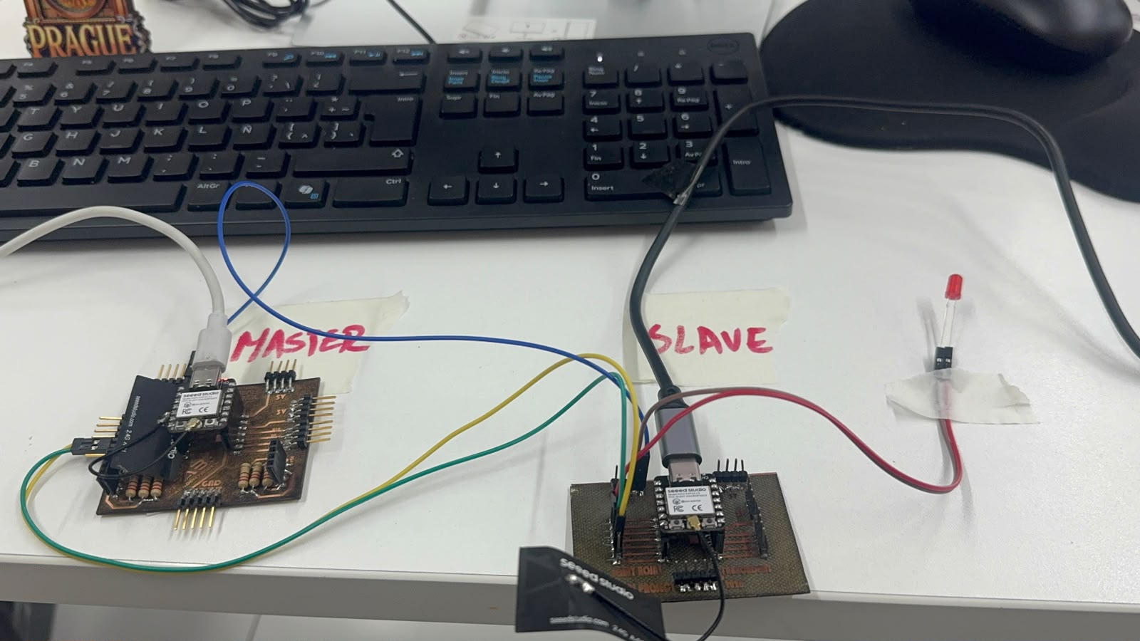
Complete UART test setup: the Master node sends addressed commands and the Slave node controls the LED output.
| Node | Board | Role | Address | Function |
|---|---|---|---|---|
| Node 1 | XIAO ESP32-C3 | Master | MASTER | Sends UART commands. |
| Node 2 | Custom PCB with XIAO ESP32-C3 | Slave | SLAVE01 | Receives commands and controls the LED. |
The Master sends the commands SLAVE01:ON and SLAVE01:OFF. The Slave responds only
when the command includes its logical address. This gives the board an address inside the small network and
makes the system easier to expand later with more nodes.
Hardware Used
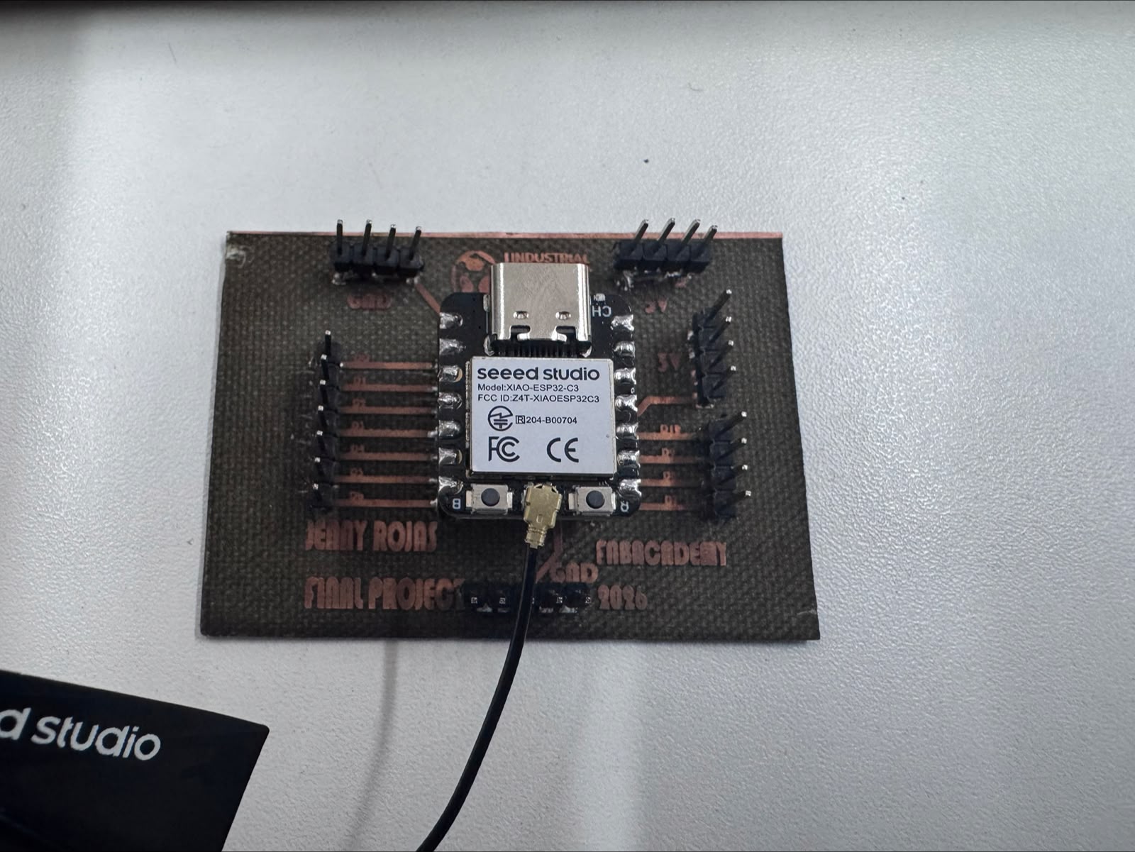
Custom fabricated PCB used as the Slave node with the XIAO ESP32-C3 module.
| Component | Quantity | Purpose |
|---|---|---|
| XIAO ESP32-C3 | 2 | Two processors used as Master and Slave nodes. |
| Custom fabricated PCB | 1 | Used as the board for the Slave node. |
| LED | 1 | Local output device. |
| 220 ohm resistor | 1 | Current limiting resistor for the LED. |
| Jumper wires | Several | UART and ground connections between nodes. |
| USB cables | 2 | Power and programming for both XIAO boards. |
UART Wiring
UART communication must be connected in crossed mode. The TX pin of the Master goes to the RX pin of the Slave, and the RX pin of the Master goes to the TX pin of the Slave. Both boards must share the same ground reference.
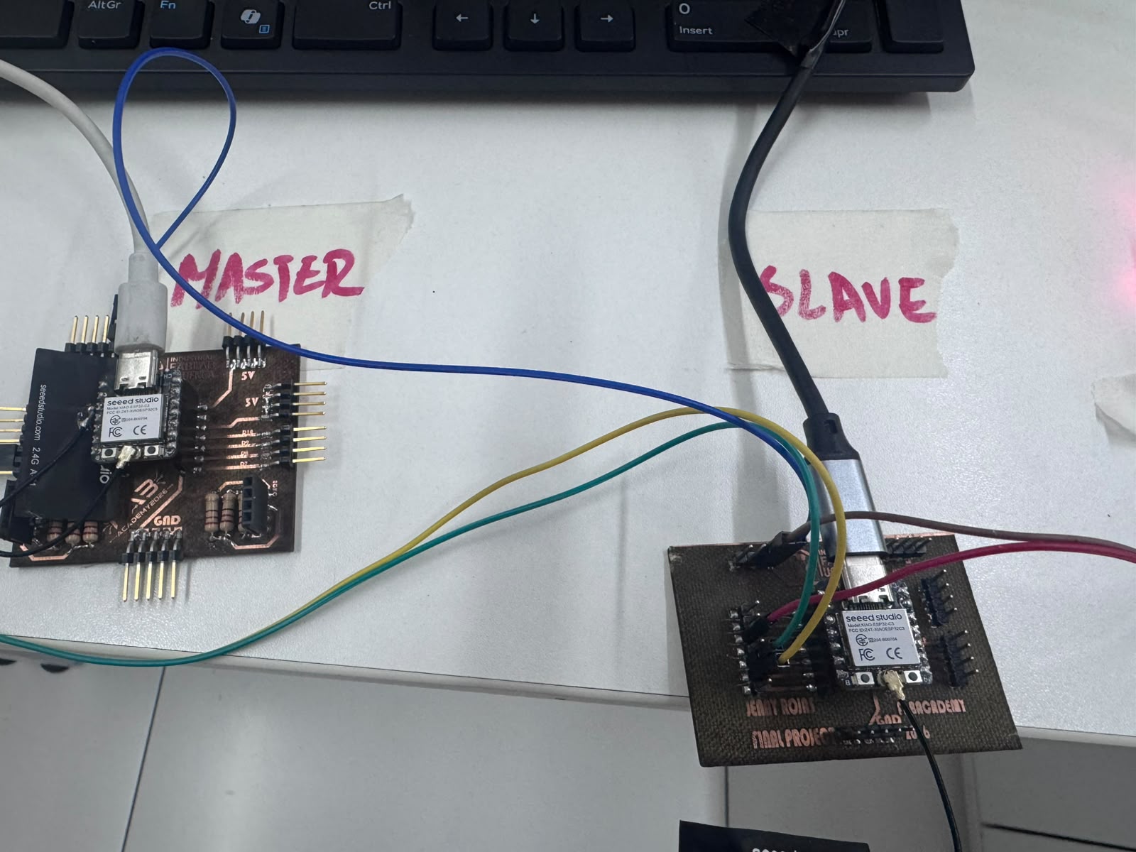
UART wiring between the two nodes. The TX and RX lines are crossed, and both boards share GND.
| Signal | Master Pin | Slave Pin | Description |
|---|---|---|---|
| UART TX to RX | D4 / TX | D5 / RX | Master sends data to the Slave. |
| UART RX from TX | D5 / RX | D4 / TX | Master receives response from the Slave. |
| Common ground | GND | GND | Required for stable communication. |
| LED Connection | Slave Pin | Description |
|---|---|---|
| LED positive leg | D2 | Digital output controlled by the Slave. |
| LED negative leg | GND through 220 ohm resistor | Current limiting and ground return. |
Communication Commands
| Command Sent by Master | Address Part | Action Part | Slave Action |
|---|---|---|---|
SLAVE01:ON |
SLAVE01 |
ON |
Turns the LED on. |
SLAVE01:OFF |
SLAVE01 |
OFF |
Turns the LED off. |
Master Node Code
// Networking and Communications - UART Master Node
// Board: XIAO ESP32-C3
// TX = D4, RX = D5
// Sends commands to SLAVE01 to control a LED

#include <HardwareSerial.h>

#define TX_PIN D4
#define RX_PIN D5

HardwareSerial NodeSerial(1);

void setup() {
  Serial.begin(115200);
  delay(3000);

  NodeSerial.begin(9600, SERIAL_8N1, RX_PIN, TX_PIN);

  Serial.println("MASTER NODE READY");
  Serial.println("UART communication started");
  Serial.println("Sending commands to SLAVE01");
}

void loop() {
  Serial.println("Sending command: SLAVE01:ON");
  NodeSerial.println("SLAVE01:ON");
  delay(3000);

  while (NodeSerial.available()) {
    String response = NodeSerial.readStringUntil('\n');
    response.trim();
    Serial.print("Response from Slave: ");
    Serial.println(response);
  }

  Serial.println("Sending command: SLAVE01:OFF");
  NodeSerial.println("SLAVE01:OFF");
  delay(3000);

  while (NodeSerial.available()) {
    String response = NodeSerial.readStringUntil('\n');
    response.trim();
    Serial.print("Response from Slave: ");
    Serial.println(response);
  }
}
Slave Node Code
// Networking and Communications - UART Slave Node
// Board: XIAO ESP32-C3 or custom PCB with XIAO ESP32-C3
// Communication: UART wired network
// TX = D4, RX = D5
// Local output device: LED on D2

#include <HardwareSerial.h>

#define RX_PIN D5
#define TX_PIN D4
#define LED_PIN D2

HardwareSerial NodeSerial(1);
String nodeAddress = "SLAVE01";

void setup() {
  Serial.begin(115200);
  delay(2000);

  pinMode(LED_PIN, OUTPUT);
  digitalWrite(LED_PIN, LOW);

  NodeSerial.begin(9600, SERIAL_8N1, RX_PIN, TX_PIN);

  Serial.println("SLAVE NODE READY");
  Serial.println("Node address: SLAVE01");
  Serial.println("Waiting for commands...");
}

void loop() {
  if (NodeSerial.available()) {
    String message = NodeSerial.readStringUntil('\n');
    message.trim();

    Serial.print("Message received: ");
    Serial.println(message);

    if (message == "SLAVE01:ON") {
      digitalWrite(LED_PIN, HIGH);
      Serial.println("LED ON");
      NodeSerial.println("SLAVE01:ACK_LED_ON");
    }
    else if (message == "SLAVE01:OFF") {
      digitalWrite(LED_PIN, LOW);
      Serial.println("LED OFF");
      NodeSerial.println("SLAVE01:ACK_LED_OFF");
    }
    else {
      Serial.println("Command not for this node or unknown command");
      NodeSerial.println("SLAVE01:UNKNOWN_COMMAND");
    }
  }
}Test Procedure
- I disconnected the motor and driver to test communication with a simple LED output first.
- I uploaded the Slave code to the custom PCB / Slave board.
- I uploaded the Master code to the second XIAO ESP32-C3 board.
- I connected UART in crossed mode: Master D4 to Slave D5, Master D5 to Slave D4, and GND to GND.
- I connected the LED to D2 on the Slave node with a 220 ohm resistor to GND.
- I opened the Serial Monitor at 115200 baud.
- The Master started sending the commands
SLAVE01:ONandSLAVE01:OFF. - The Slave received the commands and switched the LED on and off.
- The Slave returned acknowledgement messages to the Master.
Expected Serial Monitor Results
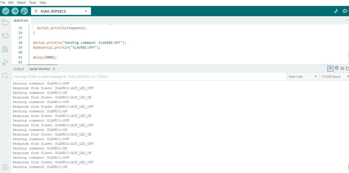
Master Serial Monitor: the Master sends SLAVE01:ON and SLAVE01:OFF, then receives acknowledgement messages from the Slave.
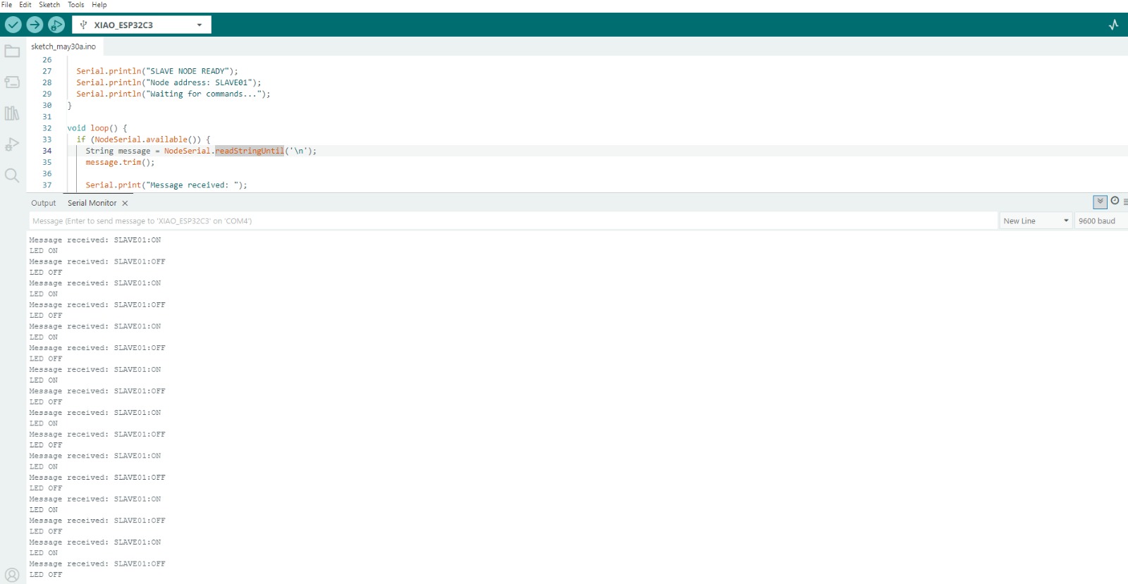
Slave Serial Monitor: the Slave receives addressed commands and changes the LED state.
MASTER NODE READY
UART communication started
Sending commands to SLAVE01
Sending command: SLAVE01:ON
Response from Slave: SLAVE01:ACK_LED_ON
Sending command: SLAVE01:OFF
Response from Slave: SLAVE01:ACK_LED_OFF
SLAVE NODE READY
Node address: SLAVE01
Waiting for commands...
Message received: SLAVE01:ON
LED ON
Message received: SLAVE01:OFF
LED OFFProblems Found and Solutions
| Problem | Cause / Observation | Solution Applied |
|---|---|---|
| Initial cloud-only implementation | It used only one ESP32 connected to an online platform, so it did not show two processors communicating. | A second processor was added and a wired UART network was implemented. |
| I2C connection was unstable | The Slave code caused upload or port recognition problems during testing. | The network was changed to UART, which was simpler and more reliable for this test. |
| Master board upload error | The message Write timeout appeared during upload. |
The USB cable was checked/replaced and the board was tested with a simple serial test before uploading the final code. |
| Only test messages appeared on Master | The Master still had the simple test code loaded. | The final UART Master code was uploaded again. |
Evidence to Include
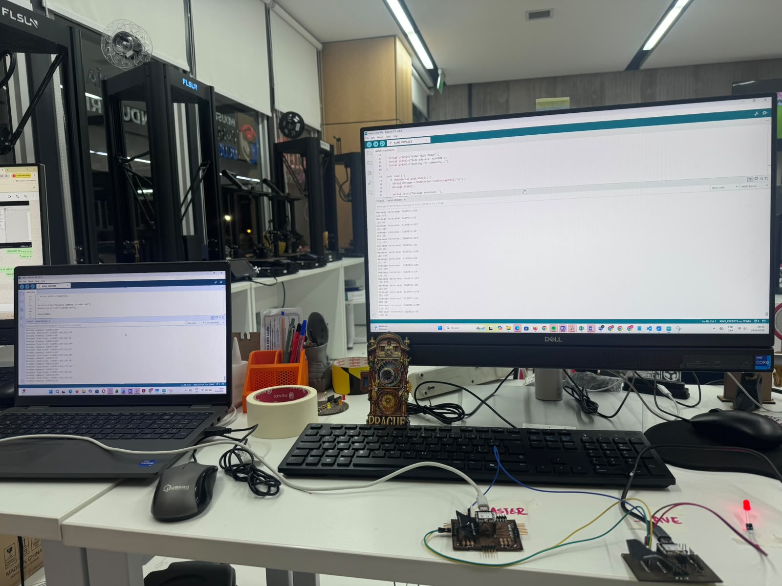
Full test evidence with both nodes running, serial monitors active, and the LED output responding on the Slave side.
| Evidence | What it should show |
|---|---|
| Photo of both nodes | The Master XIAO and the Slave custom PCB connected together. |
| Close-up of UART wiring | D4 to D5, D5 to D4, and GND to GND. |
| Photo of local output | LED connected to D2 on the Slave node. |
| Serial Monitor screenshots | Command sending, received commands, and acknowledgement messages. |
| Short video | The LED turning on and off because of commands sent by the Master. |
Hero Shot Videos
Hero shot 1: Master and Slave nodes connected through UART while the Slave LED responds to the addressed commands.
Hero shot 2: final UART communication test showing the serial feedback and the LED output behavior.
Final Explanation
This corrected assignment satisfies the main networking requirement by connecting two processors through UART, assigning the Slave a logical address, and controlling a local LED output device from the Master node. The communication is no longer only between one board and the cloud; it is a real node-to-node communication system.
13. Conclusion
This assignment allowed me to understand how networking and communications are applied in embedded systems. By using the XIAO ESP32-C6 and Blynk Cloud, I was able to connect a physical device to an IoT platform and control an LED from a virtual dashboard.
The most important learning outcome was understanding the complete communication path: the user interacts with a button in Blynk, the cloud sends the value to the ESP32-C6, the board activates the physical LED, and then the board sends a message back to the dashboard.
This practice is useful for future Fab Academy projects because the same logic can be expanded to sensors, motors, dashboards, production monitoring, automation systems, and final project applications.