Week 04 — Embedded Programming
Fab Academy 2026 · Toolchains, Development Workflows and Microcontroller Programming · XIAO ESP32-C3 · Industrial FabLab UCuenca
1. Checklist
- ✅ Linked the group assignment page
- ✅ Reviewed and documented microcontroller datasheet information
- ✅ Compared three embedded platforms
- ✅ Programmed boards to control local outputs
- ✅ Included simulation where applicable
- ✅ Documented software, code, wiring, and physical tests
- ✅ Added downloadable source files and videos
2. Group Assignment
For the group assignment, the lab explored development workflows and communication concepts between embedded platforms. This week is strongly focused on understanding toolchains, pin configurations, architecture differences, and board-to-board communication.
This individual page focuses on comparing Arduino UNO, Seeed XIAO, and Raspberry Pi 5, while the group assignment complements this comparison through practical communication testing between devices.
Open Group AssignmentIntroduction
In this individual assignment, the objective is to understand the core principles of embedded programming through hands-on experimentation using the XIAO ESP32-C3. This week focuses on learning how a microcontroller can execute programmed instructions to interact with external electronic components, such as an output device. Embedded programming is essential in digital fabrication because it allows prototypes to become interactive, responsive, and capable of communicating with the physical world.
This board is based on the ESP32-C3 microcontroller, featuring a RISC-V architecture, integrated Wi-Fi and BLE communication, low power consumption, and several programmable GPIO pins. Its compact format makes it ideal for prototyping, IoT experimentation, educational development, and electronic applications within digital fabrication environments.
The practice focuses on controlling a digital output, specifically an LED, and parameterizing its blinking behavior within a simulation environment before implementing it physically. This process helps to understand how software instructions are translated into electrical signals through a GPIO pin.
Objective
- Configure and program the XIAO ESP32-C3 using Arduino IDE.
- Use Wokwi as a simulation tool to validate the electronic circuit before physical implementation.
- Control a digital LED output through one GPIO pin of the microcontroller.
- Parameterize timing variables to modify the LED blinking behavior.
- Review the ESP32-C3 datasheet to identify relevant microcontroller characteristics.
- Document the complete programming workflow, including setup, simulation, code structure, uploading, and testing.
- Validate communication between software instructions and hardware behavior.
- Assemble the electronic circuit physically on a breadboard as an extra credit activity.
Arduino IDE — Development Environment
The programming environment used for this assignment was Arduino IDE, which allows development, compilation, and uploading of firmware to ESP32-based boards. Arduino IDE was selected because it provides a clear and accessible workflow for embedded programming, especially when working with development boards such as the XIAO ESP32-C3.
Installation and Setup Steps:
- Download and install Arduino IDE.
- Open Preferences.
- Add the ESP32 board manager URL.
- Open Boards Manager and install ESP32 package.
- Select board: XIAO ESP32-C3.
- Select correct COM port.
- Verify that compilation completes without errors.
Visual Evidence:
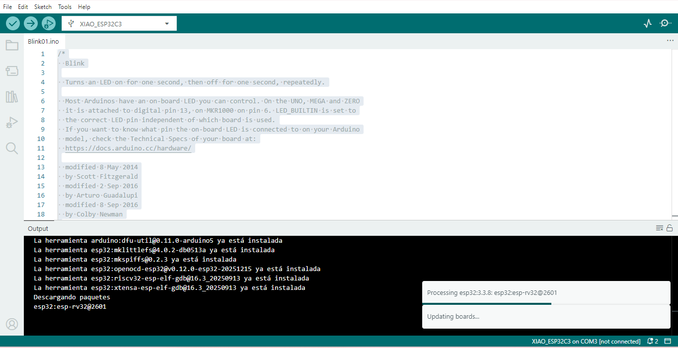
Figure 1. Arduino IDE configuration process for programming the XIAO ESP32-C3 board.
Wokwi — Online Simulation
Before physical implementation, the circuit was tested using Wokwi, an online simulator that supports ESP32 microcontrollers. This simulation step was useful to verify the behavior of the LED circuit before connecting the real components on a breadboard.
Simulation Steps:
- Open Wokwi platform.
- Select ESP32 board model.
- Add LED component.
- Add resistor (220Ω).
- Connect GPIO 3 → LED → Resistor → GND.
- Paste Arduino code.
- Run simulation.
Video 1. Wokwi simulation showing the LED ON/OFF behavior controlled by the ESP32 program.
Electronic Configuration
The electronic configuration was designed to control a simple output device using the XIAO ESP32-C3. The LED was connected to a GPIO pin so that the microcontroller could turn it ON and OFF according to the uploaded program. A resistor was included to limit the current and protect the LED.
Components used:
- XIAO ESP32-C3
- 1 LED
- 220Ω resistor
- Jumper wires
Connection Logic:
GPIO 3 → LED Anode
LED Cathode → 220Ω resistor
Resistor → GND
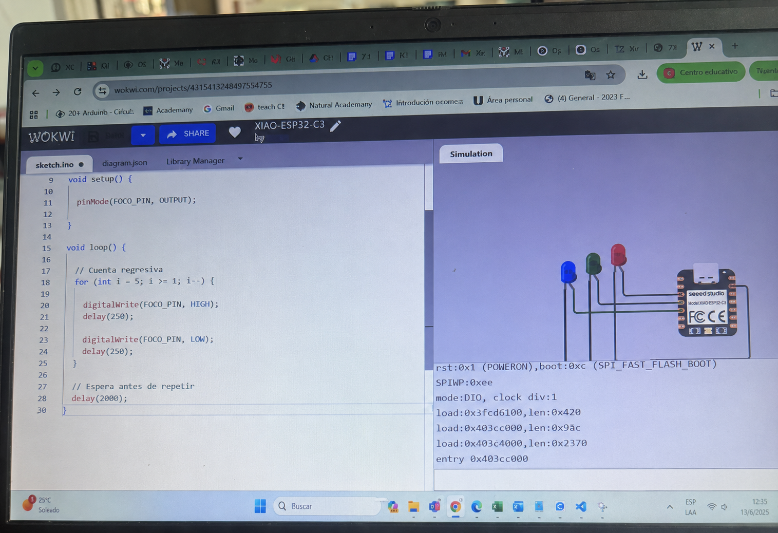
Figure 2. Electronic configuration of the LED circuit using the XIAO ESP32-C3, LED, and 220Ω resistor.
Parameterized Code Structure
Instead of using fixed delays, timing variables were defined to allow flexible control of LED behavior. This makes the code easier to understand, modify, and reuse. By changing the values of onTime and offTime, different blinking patterns can be tested without changing the main structure of the program.
// Parameter definition
const int ledPin = 3;
int onTime = 1000;
int offTime = 1000;

void setup() {
  pinMode(ledPin, OUTPUT);
}

void loop() {
  digitalWrite(ledPin, HIGH);
  delay(onTime);

  digitalWrite(ledPin, LOW);
  delay(offTime);
}
Physical Assembly on Breadboard
After testing the circuit in simulation, the system was assembled physically on a breadboard. This step allowed the virtual design to be validated with real components, confirming the correct connection between the XIAO ESP32-C3, the LED, the resistor, and the ground rail.
- Insert XIAO ESP32-C3 into breadboard.
- Connect GPIO 3 to LED anode.
- Connect LED cathode to 220Ω resistor.
- Connect resistor to GND rail.
- Connect USB cable for power and programming.
- Upload final tested code.
Assembly Process:
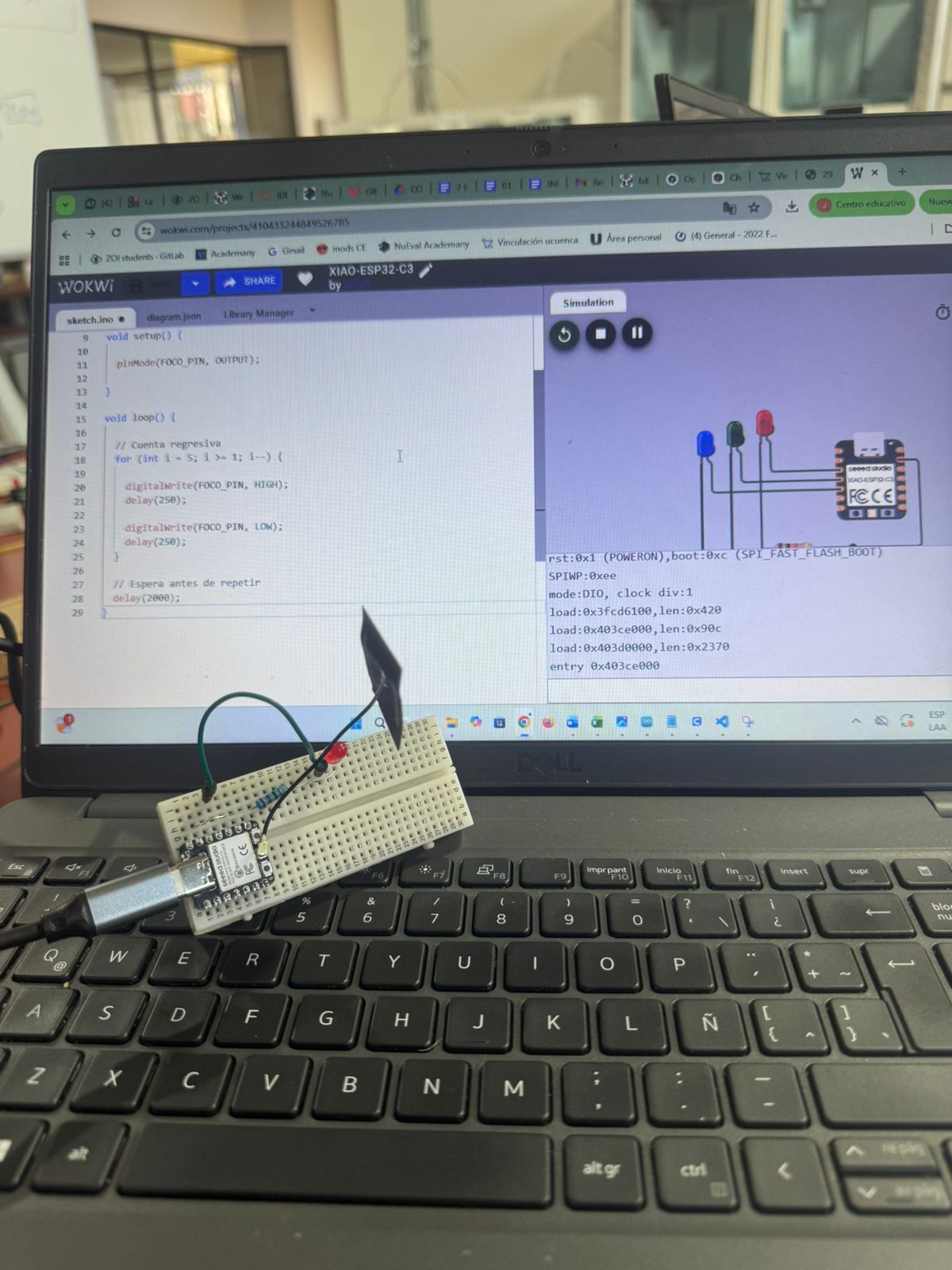
Figure 3. Physical assembly of the XIAO ESP32-C3 circuit on a breadboard with LED and resistor.
Hero Shot
The final result shows the LED blinking successfully using the XIAO ESP32-C3 and the uploaded parameterized code. This confirms that the embedded program was correctly compiled, uploaded, and executed on the physical microcontroller.
Circuit Diagram / Video:
Video 2. Final hero shot showing the LED blinking on the physical circuit after uploading the program.
Conclusion
This individual assignment successfully demonstrated the fundamentals of digital output programming using the XIAO ESP32-C3. Through this activity, it was possible to understand how a microcontroller can control an external output device using simple embedded programming logic.
By integrating Arduino IDE for development and Wokwi for simulation, a complete iterative workflow was established:
Simulation → Validation → Upload → Physical Implementation
The use of parameterized variables improved flexibility and scalability of the code, allowing different blinking behaviors to be tested easily. This also helped reinforce the importance of writing clear and adjustable code for embedded systems.
This practice strengthens understanding of GPIO configuration, embedded logic, simulation validation, microcontroller programming workflow, and hardware-software interaction. It also provides a foundation for future Fab Academy assignments involving sensors, communication systems, automation, and IoT-based applications.
Final Checklist
- ✅ Linked to the group assignment page
- ✅ Browsed and documented information from a microcontroller’s datasheet
- ✅ Programmed a board to interact and communicate
- ✅ Described the programming process used
- ✅ Included the source code
- ✅ Included hero shots