WEEK 10 - Output Devices
Group Assignment
The group assignment for Output Devices focused on measuring the power consumption of an output device and understanding how a microcontroller can safely control external components. This is important because output devices normally require current, voltage limits, resistors, drivers, or protection elements depending on the load.
In my individual work I applied this idea with a simple and clear output: a DC geared motor controlled through an L298N motor driver. This allowed me to understand how a microcontroller sends low-current logic signals while the driver supplies the power required by the actuator.
Individual Assignment
XIAO ESP32C3 + L298N Motor Driver + DC Geared Motor
Introduction
This week focused on the implementation of an electromechanical output system using the Seeed Studio XIAO ESP32C3. The main objective was to control a DC geared motor through an L298N H-Bridge driver, allowing the microcontroller to command mechanical motion without directly supplying the motor current.
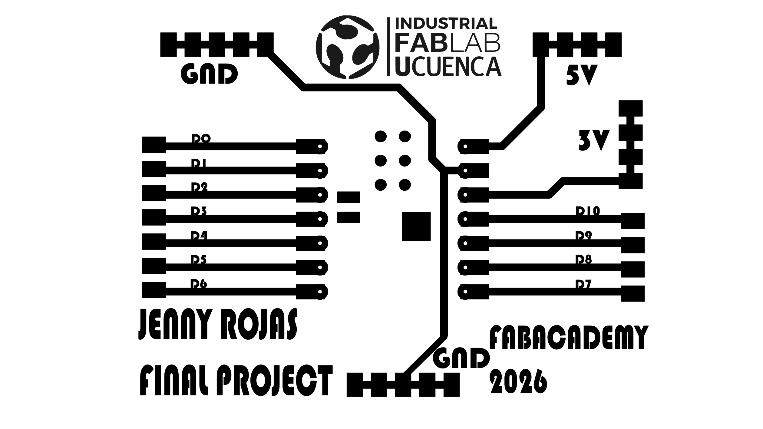
For this specific assignment, I used my own PCB as the control board for the XIAO ESP32C3. This board was designed and fabricated as part of my learning process, with the final project in mind. The focus of this work was the integration of the actuator, the motor driver, the power supply, and the embedded programming required to control the motor.
This exercise is directly connected to my final project: an autonomous orchid immersion irrigation system. In that system, controlled mechanical movement is required to activate the immersion mechanism. Therefore, this prototype validates an essential actuator subsystem by integrating embedded programming, power electronics, motor control, and mechanical output.
System Concept
The selected output device was a DC geared motor. This type of actuator converts electrical energy into rotational mechanical energy while the gearbox reduces speed and increases torque. For this assignment, the motor was used as a functional prototype to evaluate motor activation and mechanical motion for a future lifting or immersion mechanism.
Since the XIAO ESP32C3 operates at logic-level voltage and cannot provide the current required by the motor, the system required an intermediate power stage. The L298N driver was used as an H-Bridge interface between the microcontroller and the motor.
- Control unit: Self-made PCB with Seeed Studio XIAO ESP32C3, designed with the final project in mind
- Power interface: L298N H-Bridge motor driver
- Output device: DC geared motor
- Power source: External DC laboratory power supply
- Programming environment: Arduino IDE
Electronic Architecture
The electronic architecture separates the control stage from the power stage. The XIAO ESP32C3 generates low-current digital signals, while the L298N driver supplies the motor with the required voltage and current from an external source.
PCB with XIAO ESP32C3
(Self-made board for final project development)
        │
        │ Digital control signals
        ▼
L298N H-Bridge Motor Driver
        │
        │ Power output
        ▼
DC Geared Motor
This architecture protects the microcontroller from high motor current and allows the actuator to be controlled safely through digital outputs.
Control Board Used in this Assignment
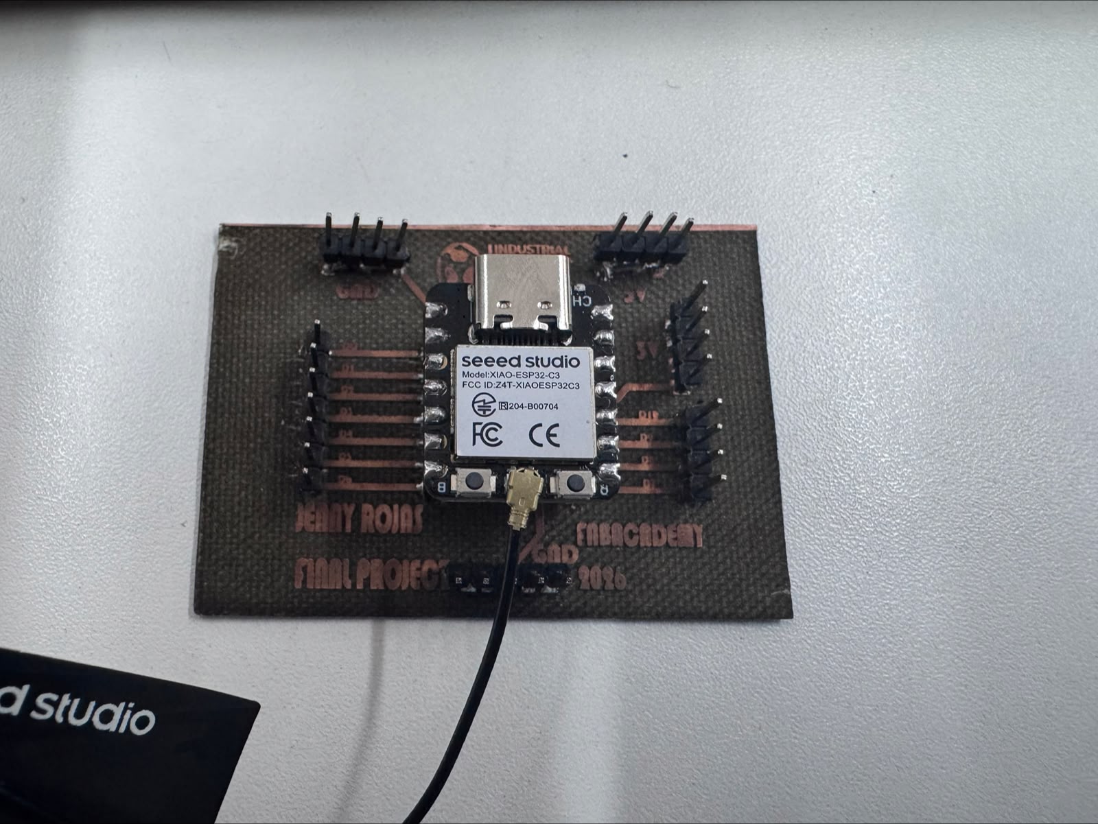
For this assignment, I used a self-made PCB as the control platform for the Seeed Studio XIAO ESP32C3. This board was designed and fabricated by me, and it was also planned as a useful control board for the final project.
The board provided access to the microcontroller GPIO pins, allowing the connection of the L298N motor driver and the DC geared motor used during the experiments. Using my own board allowed me to connect this output-device test with the development of the actuator subsystem for the final project.
This control board is part of my own fabrication process. It helped me test motor control for Week 10 while also preparing a practical electronics platform for the autonomous orchid irrigation final project.
L298N Motor Driver Integration
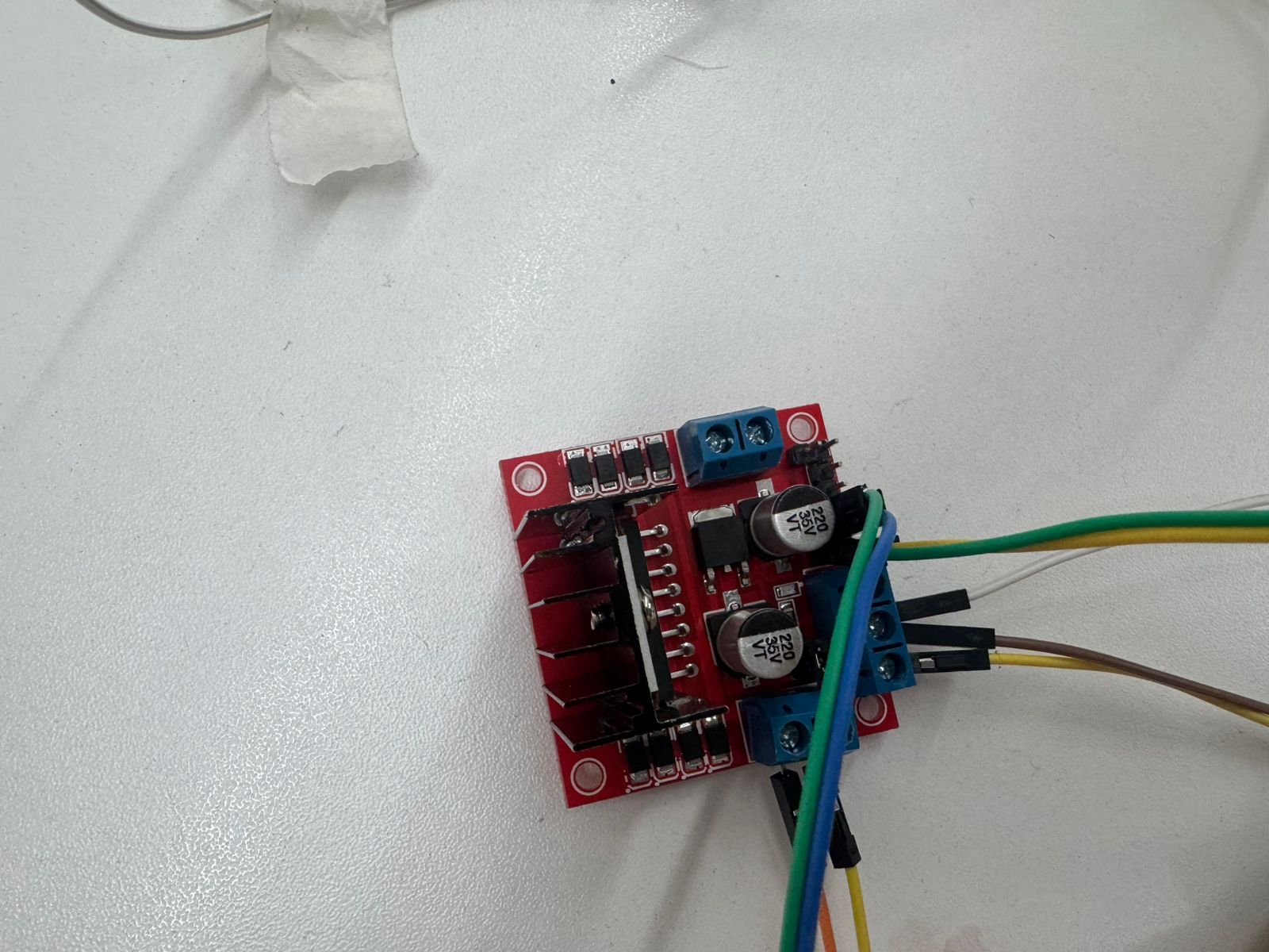
The L298N module was used as the power driver for the DC motor. This driver contains an H-Bridge circuit that allows the polarity applied to the motor terminals to be reversed, making bidirectional rotation possible when required.
In this prototype, the ENA jumper was kept installed on the L298N module. This means that the motor operated at full speed, while the XIAO ESP32C3 controlled the motor activation through the IN1 and IN2 pins.
Output Device: DC Geared Motor
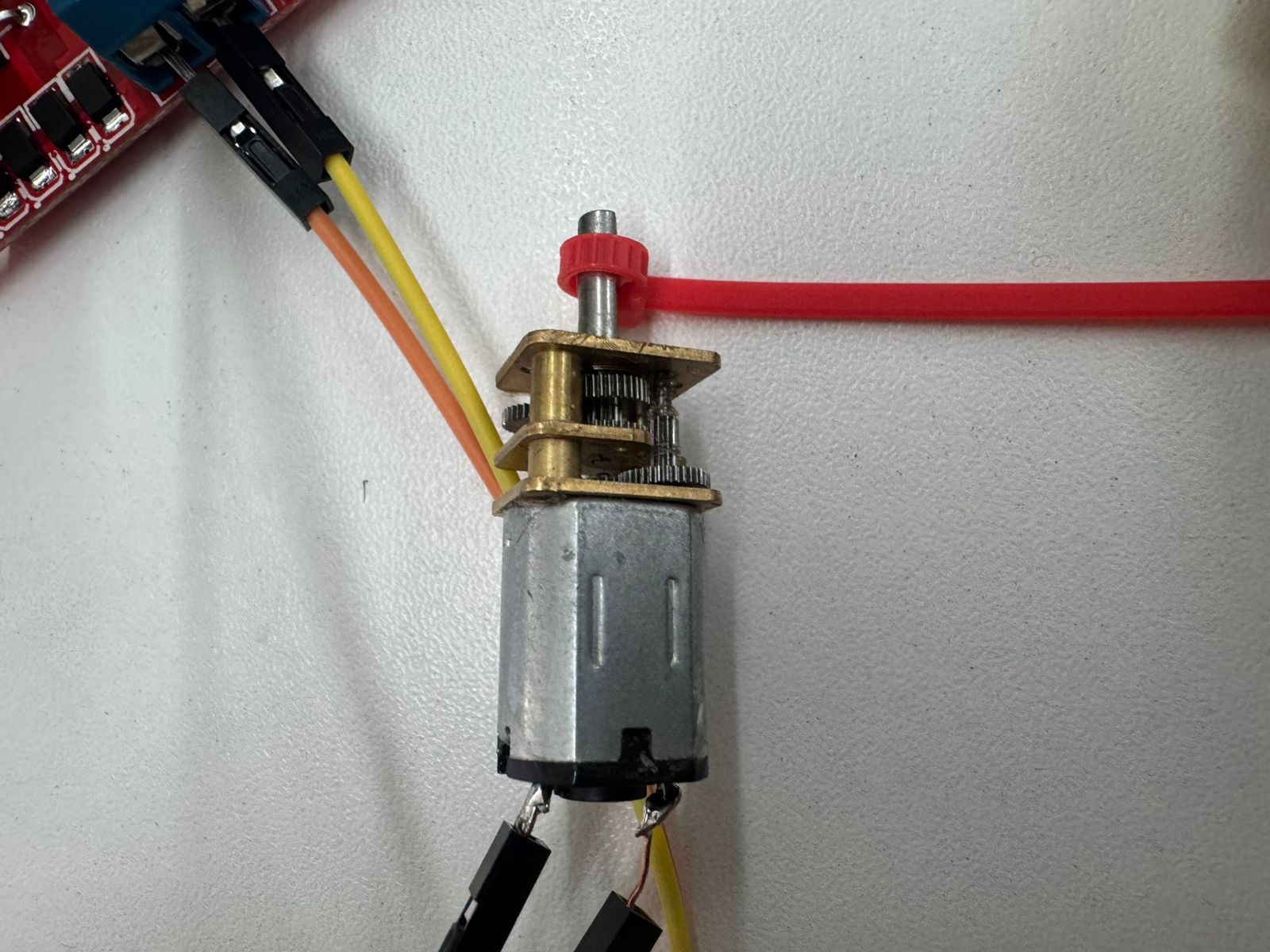
The selected output device was a small DC geared motor. The integrated gearbox reduces the output speed and increases the available torque, which is useful for mechanisms that require slower and stronger movement.
This motor is appropriate for the first functional tests of my final project because the immersion irrigation system requires controlled mechanical movement rather than high-speed rotation. The prototype allowed me to evaluate whether the actuator could respond correctly to the control signals sent from the microcontroller through the motor driver.
Wiring Connections
The motor driver was connected to the XIAO ESP32C3 using two digital output pins. The motor was powered independently through the L298N module using an external DC power supply. A common ground was required between the XIAO ESP32C3, the L298N driver, and the power supply to ensure that the logic signals had the same reference voltage.
| Component / Pin | Connection | Technical Function |
|---|---|---|
| XIAO ESP32C3 D8 | L298N IN1 | Motor control signal 1 |
| XIAO ESP32C3 D9 | L298N IN2 | Motor control signal 2 |
| XIAO ESP32C3 GND | L298N GND | Common signal reference |
| External power supply + | L298N +12V input | Motor power supply |
| External power supply - | L298N GND | Power return and common ground |
| L298N OUT1 / OUT2 | DC motor terminals | Motor power output |
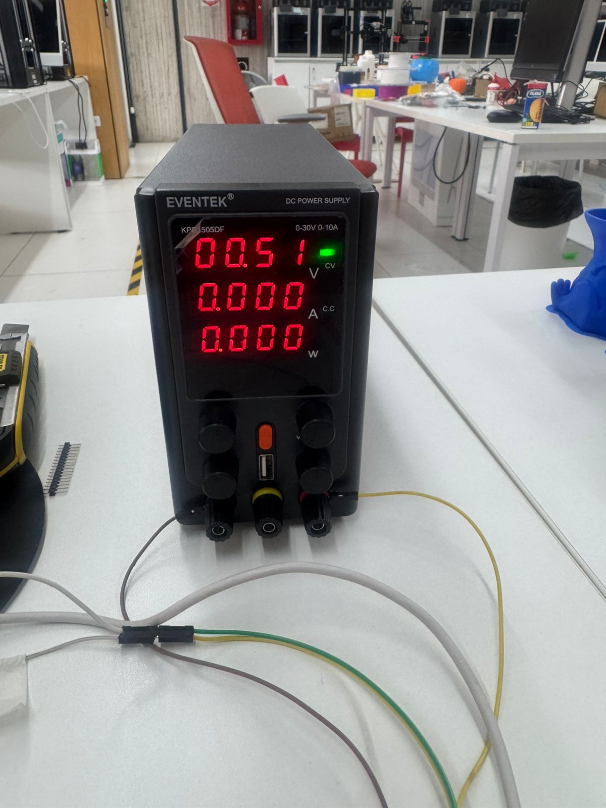
Power Supply Test
During the validation stage, a laboratory DC power supply was used to provide a controlled voltage to the motor driver. This allowed me to gradually verify the motor behavior and avoid overloading the microcontroller.
The power supply was connected directly to the L298N motor input. The XIAO ESP32C3 only provided the logic control signals, while the motor current was supplied by the external source.
Programming
The control program was developed in Arduino IDE. The logic is based on changing the state of two digital outputs connected to IN1 and IN2 of the L298N driver. Depending on the combination of these two signals, the motor rotates in one direction, rotates in the opposite direction, or stops.
// XIAO ESP32C3 + L298N
// Week 10 - Output Devices
// DC geared motor control

#define IN1 D8
#define IN2 D9

void setup() {

  pinMode(IN1, OUTPUT);
  pinMode(IN2, OUTPUT);

  // Initial safe state: motor stopped
  digitalWrite(IN1, LOW);
  digitalWrite(IN2, LOW);
}

void loop() {

  // Rotate in one direction for 2 seconds
  digitalWrite(IN1, HIGH);
  digitalWrite(IN2, LOW);
  delay(2000);

  // Stop motor for 1 second
  digitalWrite(IN1, LOW);
  digitalWrite(IN2, LOW);
  delay(1000);

  // Rotate in the opposite direction for 2 seconds
  digitalWrite(IN1, LOW);
  digitalWrite(IN2, HIGH);
  delay(2000);

  // Stop motor for 1 second
  digitalWrite(IN1, LOW);
  digitalWrite(IN2, LOW);
  delay(1000);
}
This sequence was used to confirm that the driver could control the motor output through the digital signals generated by the XIAO ESP32C3.
Control Logic
| IN1 | IN2 | Motor State |
|---|---|---|
| HIGH | LOW | Rotation in one direction |
| LOW | HIGH | Rotation in the opposite direction |
| LOW | LOW | Motor stopped |
| HIGH | HIGH | Brake condition / not used in this test |
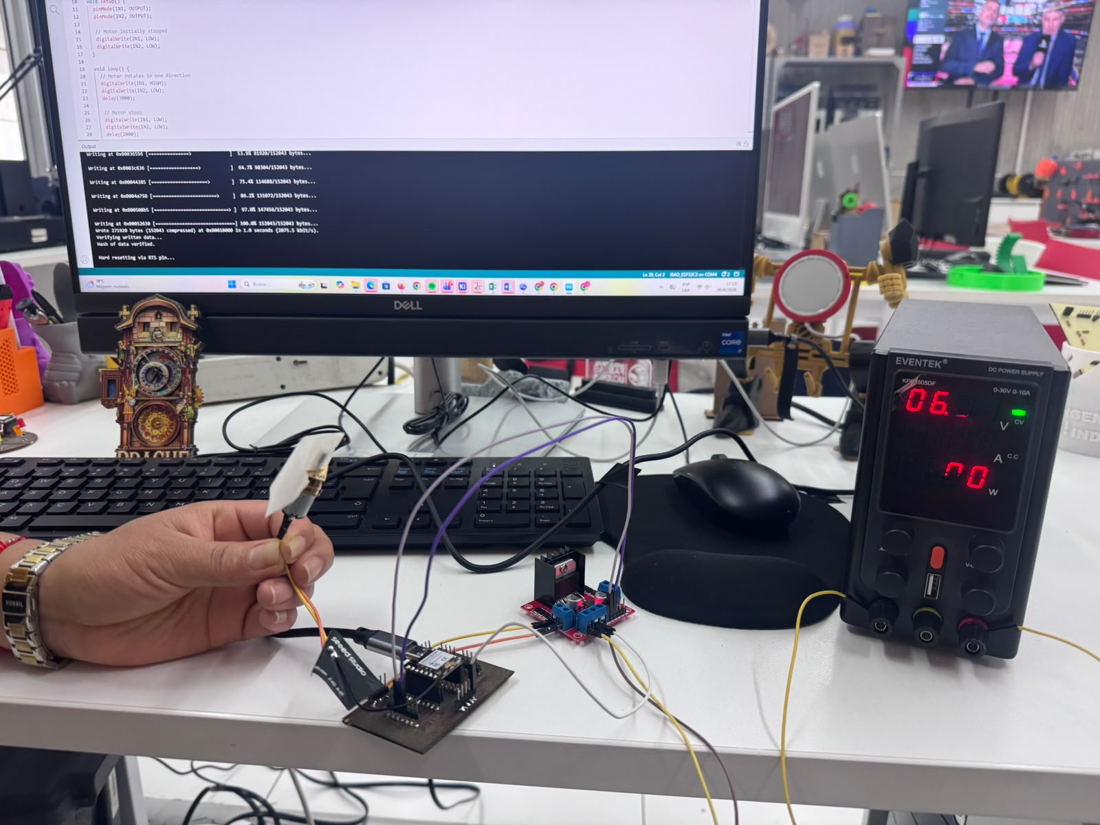
Testing and Validation
After uploading the program to the XIAO ESP32C3, I tested the complete system by observing the motor response to each programmed state. The motor successfully rotated and stopped between movements, confirming that the driver and the PCB were correctly integrated.
The tests also helped verify the importance of correct wiring, common ground, and stable external power supply. These factors are essential when working with output devices that consume more current than a microcontroller pin can provide.
Problems and Solutions
Problem 1: The motor did not rotate during the first test
During the first connection attempts, the motor did not respond to the programmed commands. The issue was related to the initial selection of GPIO pins and incomplete verification of the motor driver wiring.
Solution
I reviewed the pin mapping of the XIAO ESP32C3, tested alternative digital pins, and finally used D8 and D9 for the control signals. I also confirmed that the ENA jumper was installed and that the motor was connected to the correct L298N output terminals.
Problem 2: The motor required more power than the microcontroller could provide
The DC motor could not be powered directly from the XIAO ESP32C3 because the microcontroller pins are designed only for logic signals, not for motor current.
Solution
The L298N driver was used as the power interface, and the motor was powered with an external DC source. The XIAO ESP32C3 was used only to send logic-level control signals to the driver.
Problem 3: The system required a common reference voltage
Without a shared ground reference, the logic signals from the XIAO ESP32C3 could not be interpreted reliably by the L298N driver.
Solution
I connected the GND of the XIAO ESP32C3, the GND of the L298N, and the negative terminal of the external power supply together. This ensured a common electrical reference for both the control and power stages.
Results
The output device was successfully integrated and controlled using my own XIAO ESP32C3 control board. The system demonstrated motor control through the L298N H-Bridge driver and confirmed that the actuator can be commanded from embedded software.
This result validates an important subsystem for my final project. The motor control architecture can be further developed to include limit switches, feedback sensors, timing control, and automated irrigation cycles.
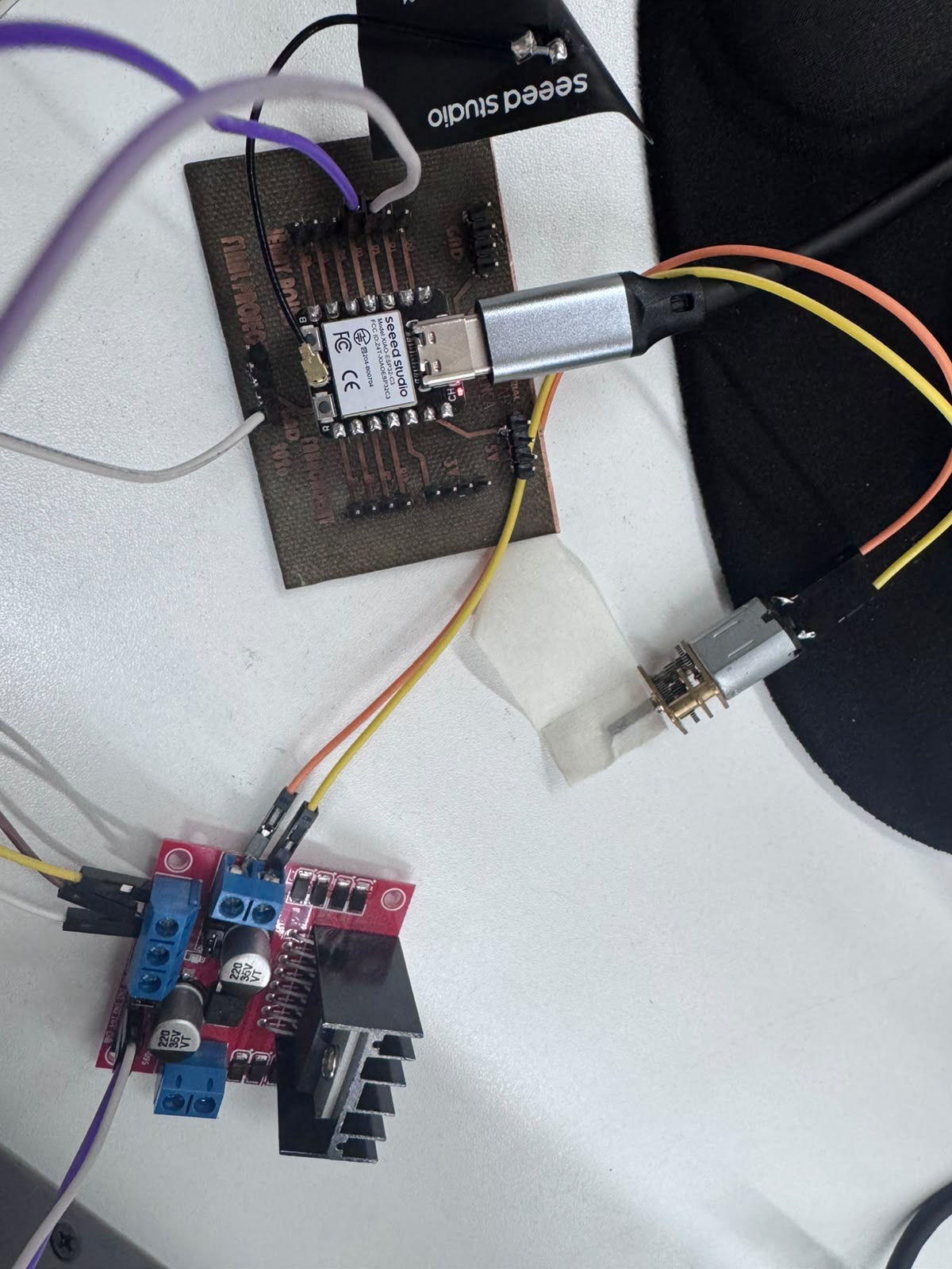
Hero Shot
The final prototype integrates my self-made XIAO ESP32C3 control board, L298N motor driver, DC geared motor, and laboratory power supply into a complete output device system.
This assembly demonstrates the successful conversion of digital control signals into controlled mechanical movement, representing the first functional actuator stage for the autonomous orchid immersion irrigation project.
Final Conclusion
This assignment allowed me to implement and validate an output device using a self-made XIAO ESP32C3 control board. The PCB was developed as part of my own fabrication process and also supports the electronics direction of my final project. My work focused on the integration of the motor driver, actuator, wiring, programming, and functional validation.
The main technical learning was the difference between the control stage and the power stage in an embedded system. I also reinforced the importance of correct GPIO selection, common ground connection, external power supply, and systematic troubleshooting when working with actuators.
The final result is a functional actuator prototype that will support the mechanical development of my final project. This week helped me move from basic electronic control to a more integrated electromechanical system capable of producing real physical movement.
Downloadable Files
The following files can be included to document and reproduce the output device test:
Student Checklist — Fab Academy
- ✔ I added an output device to a microcontroller board used for this assignment.
- ✔ I used a self-made PCB designed with my final project in mind.
- ✔ I programmed the board to control the output device.
- ✔ I used an external motor driver to separate logic control from motor power.
- ✔ I documented the wiring, code, testing process, and troubleshooting.
- ✔ I included photo evidence of the working output device.
- ✔ I connected the assignment to the actuator subsystem of my final project.