Week 17: Wildcard Week
Topic: Fiber laser engraving and cutting in aluminum.
Assignment Goal
For this wildcard assignment I explored a fabrication technology that was not covered in the regular Fab Academy workflow: fiber laser machining on metal. I designed a small aluminum keychain using Fusion 360, prepared the vector paths in EZCAD / ez CAST, calibrated the fiber laser, engraved the graphic details, and cut the external contour through repeated laser passes.
The exercise was important for me because it connected digital design with a material that is much harder to process than MDF, acrylic, vinyl, or PLA. Instead of only marking a surface, I tested the machine until the aluminum part was fully released after 50 passes.
Why This Is Wildcard
During Fab Academy I used common digital fabrication workflows such as 3D printing, laser cutting in MDF, electronics production, and CNC-related design logic. Fiber laser cutting in aluminum was a new process for my documentation because it requires different machine behavior: metal absorbs energy differently, the focus point is more critical, and the cut is achieved through repeated passes instead of a single standard cutting operation.
Design in Fusion 360
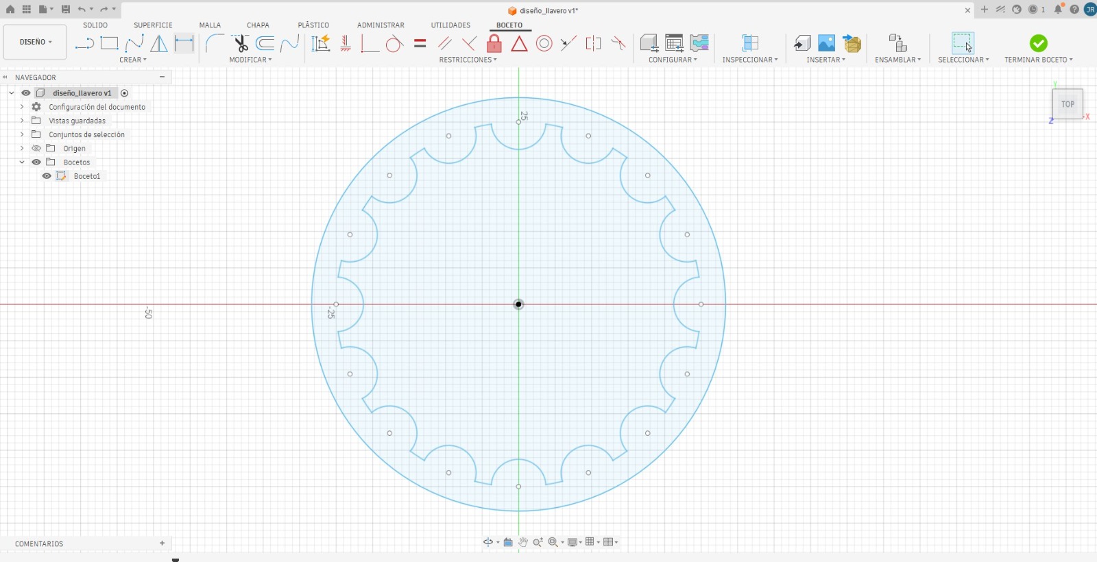
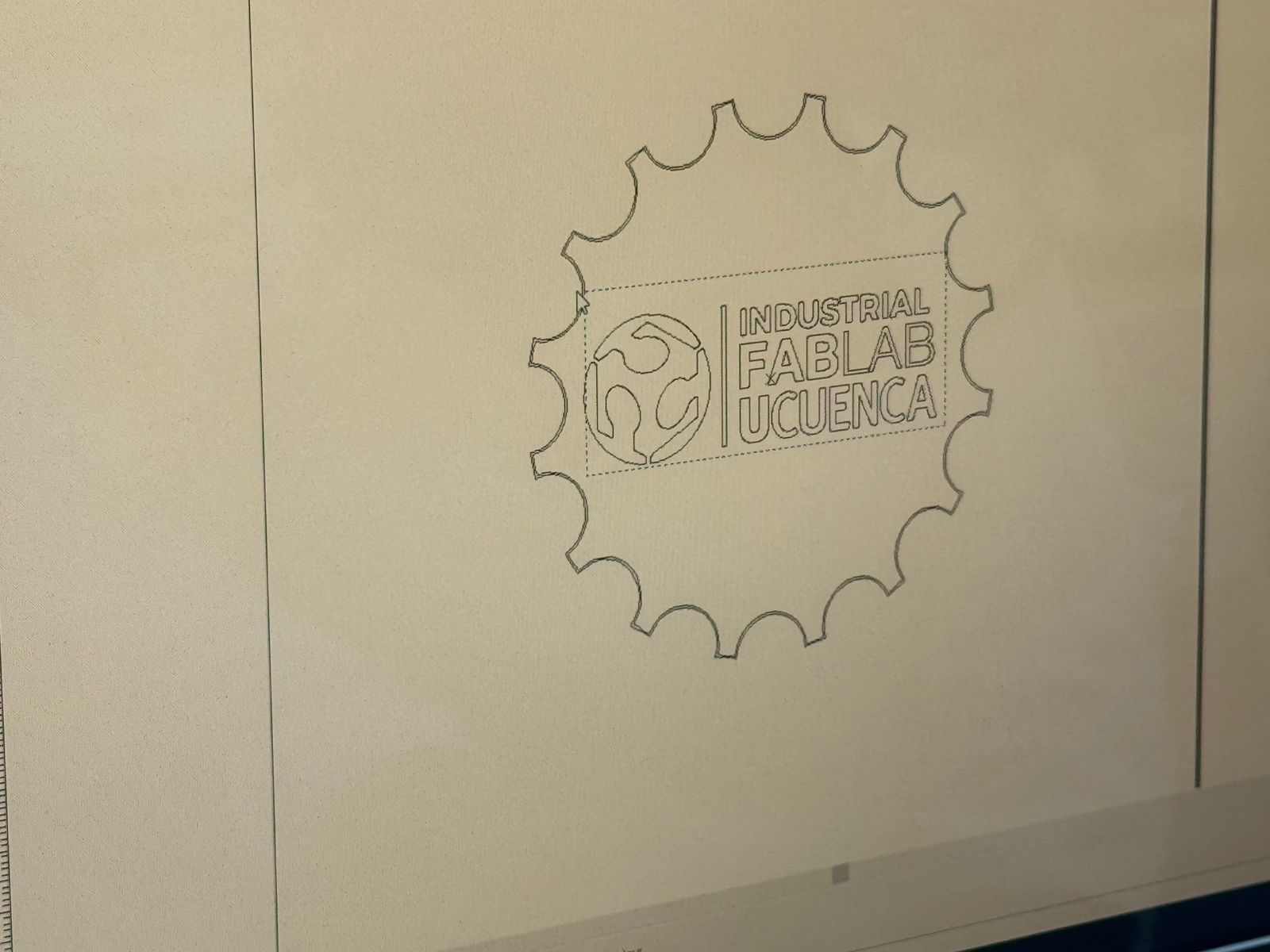
I started the keychain in Fusion 360 as a flat 2D profile. The main silhouette was created as a circular piece with a gear-like perimeter. This gave the object a mechanical identity and made it visually connected to fabrication. I then added the Industrial FabLab UCuenca logo and text, separating the design intent into two groups: the external contour for cutting and the internal graphics for engraving.
Files and Setup
| Item | Description |
|---|---|
| Material | Aluminum sheet for engraving and cutting tests. |
| Design software | Fusion 360, used to draw the keychain profile, logo layout, and cutting geometry. |
| Laser software | EZCAD / ez CAST, used for vector preparation, layer organization, positioning, and machine control. |
| Machine | Fiber laser system for metal engraving and cutting. |
| Operations | Vector engraving for the logo and text, plus repeated-pass cutting for the external contour. |
| Cut result | The aluminum piece detached from the sheet after 50 passes. |
Vectorization and Calibration
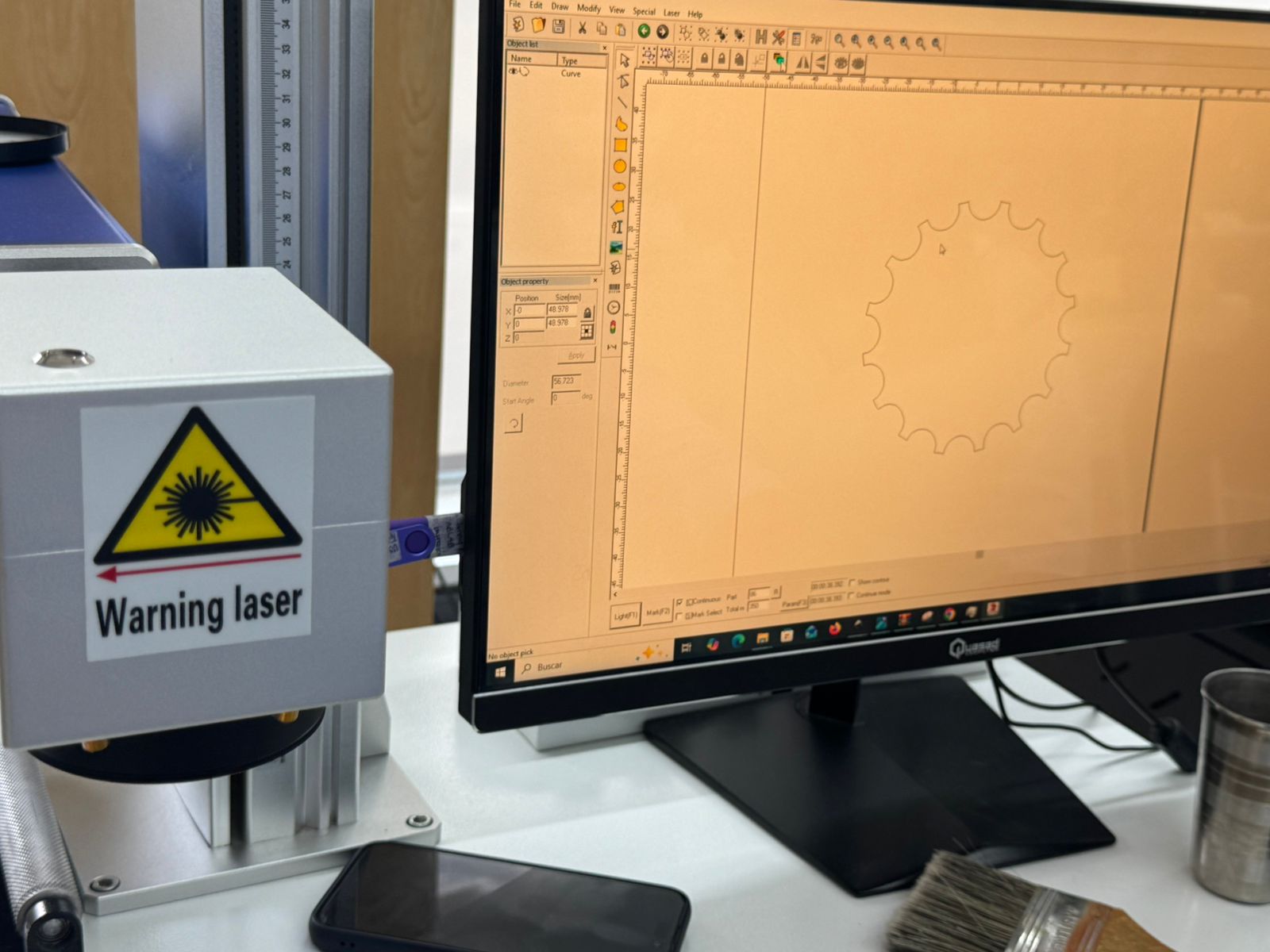
After finishing the CAD file, I moved the design to the laser software. In EZCAD / ez CAST I checked that the curves were correctly interpreted as vectors, adjusted the size and placement, and separated the job into engraving and cutting operations. This step was essential because the machine needs clean vector paths to follow the gear outline without interruptions.
Complete Process
CAD definition
I modeled the keychain as a flat manufacturing file in Fusion 360. The design included the external gear-like perimeter, small reference holes, and the internal FabLab UCuenca graphic for engraving.
Vector preparation
In EZCAD / ez CAST I reviewed the imported geometry, verified the closed contour, and organized the linework so that engraving and cutting could be controlled separately.
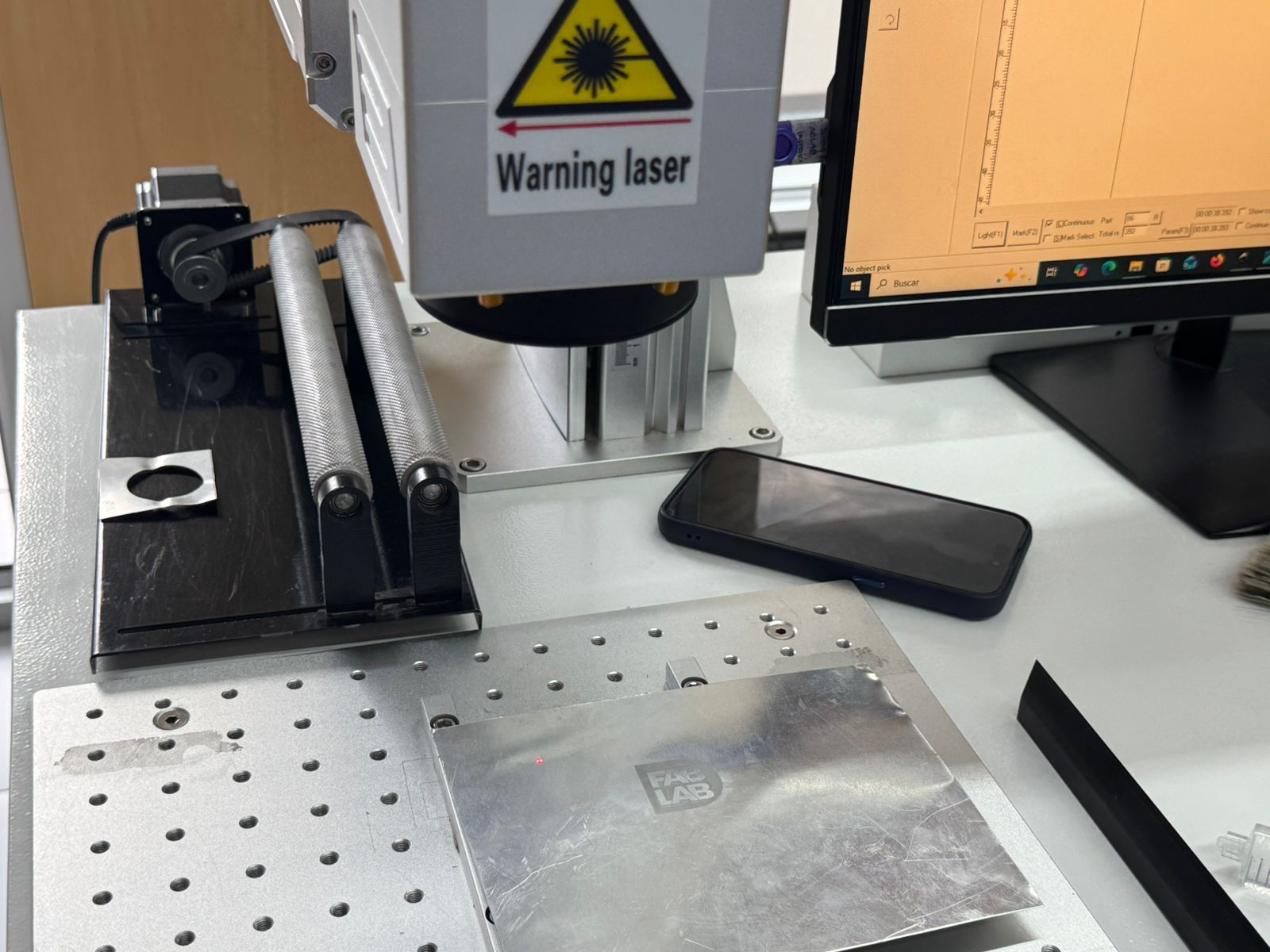
Machine calibration
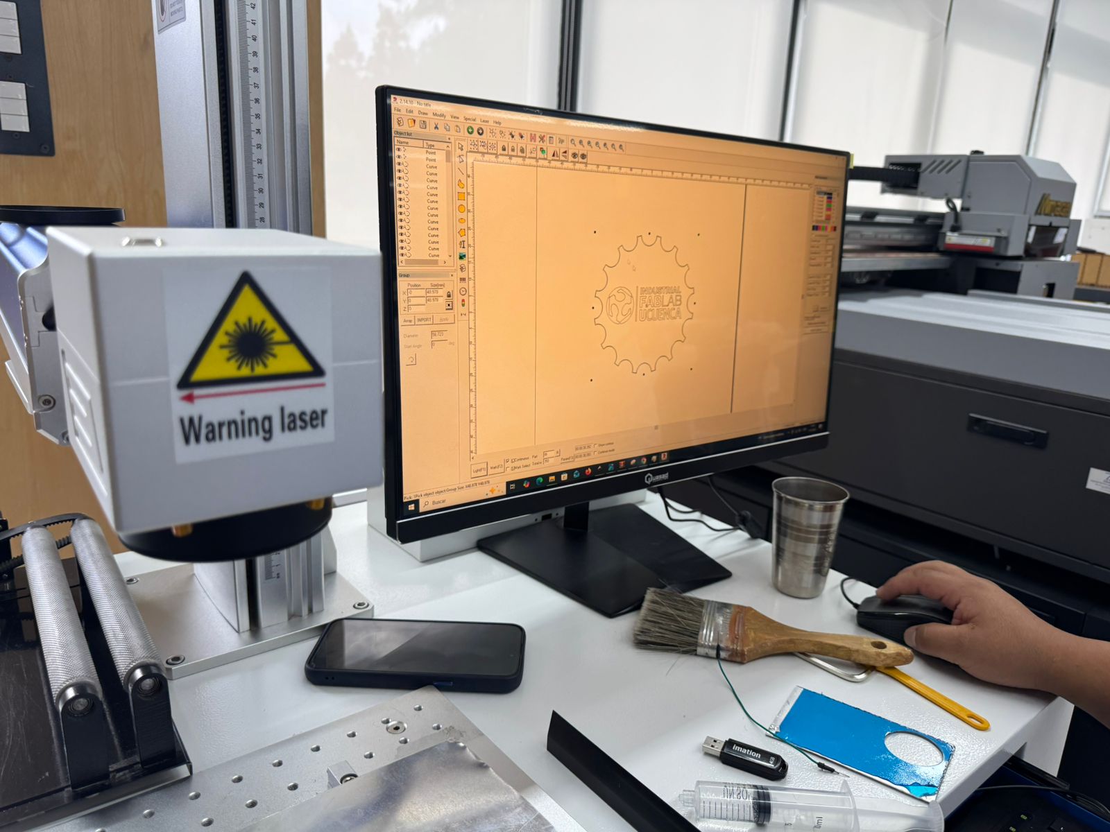
I positioned the aluminum sheet on the working table, adjusted the focus, aligned the origin, and checked the laser preview. The calibration had to be precise because even a small displacement would affect the logo and the perimeter cut.
Engraving test
I first engraved the logo and text to validate the contrast on aluminum. This gave me a reference for the machine response before attempting the deeper cutting operation.
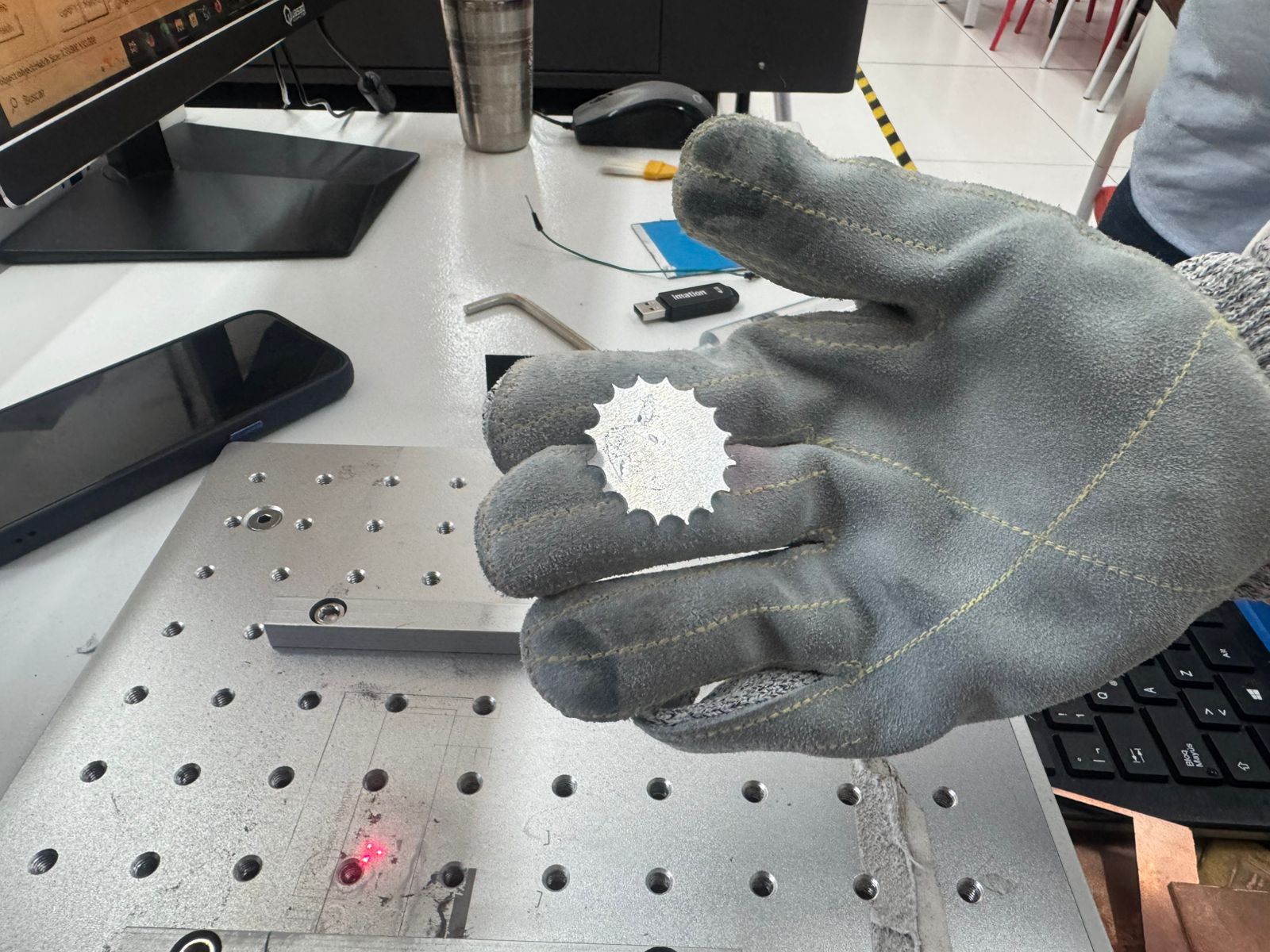
Repeated-pass cutting
The external contour was cut through multiple passes. Since aluminum requires more energy than softer materials, I repeated the path until the piece separated. The final detachment happened after 50 passes.
Engraving and Cutting Evidence
The engraving test confirmed that the fiber laser could mark the aluminum surface clearly. For cutting, I used the same vector contour repeatedly, increasing the depth pass by pass until the profile was free from the sheet.
Process Videos
These videos document the active laser workflow during the aluminum test. They show the machine operating over the vector paths and helped me confirm the relationship between the software setup, the physical work area, and the repeated passes needed to release the final part.
Problems and Adjustments
| Challenge | Adjustment | Learning |
|---|---|---|
| Metal cutting was slower than expected. | I repeated the contour path until the cut accumulated enough depth. | Fiber laser cutting in aluminum depends strongly on pass strategy and calibration. |
| The logo needed clean vector lines. | I checked the imported curves and separated engraving from cutting geometry. | Good vector preparation prevents unwanted marks and path errors. |
| Focus and origin were critical. | I calibrated the machine before running the final job. | In metal laser work, small setup errors become visible immediately. |
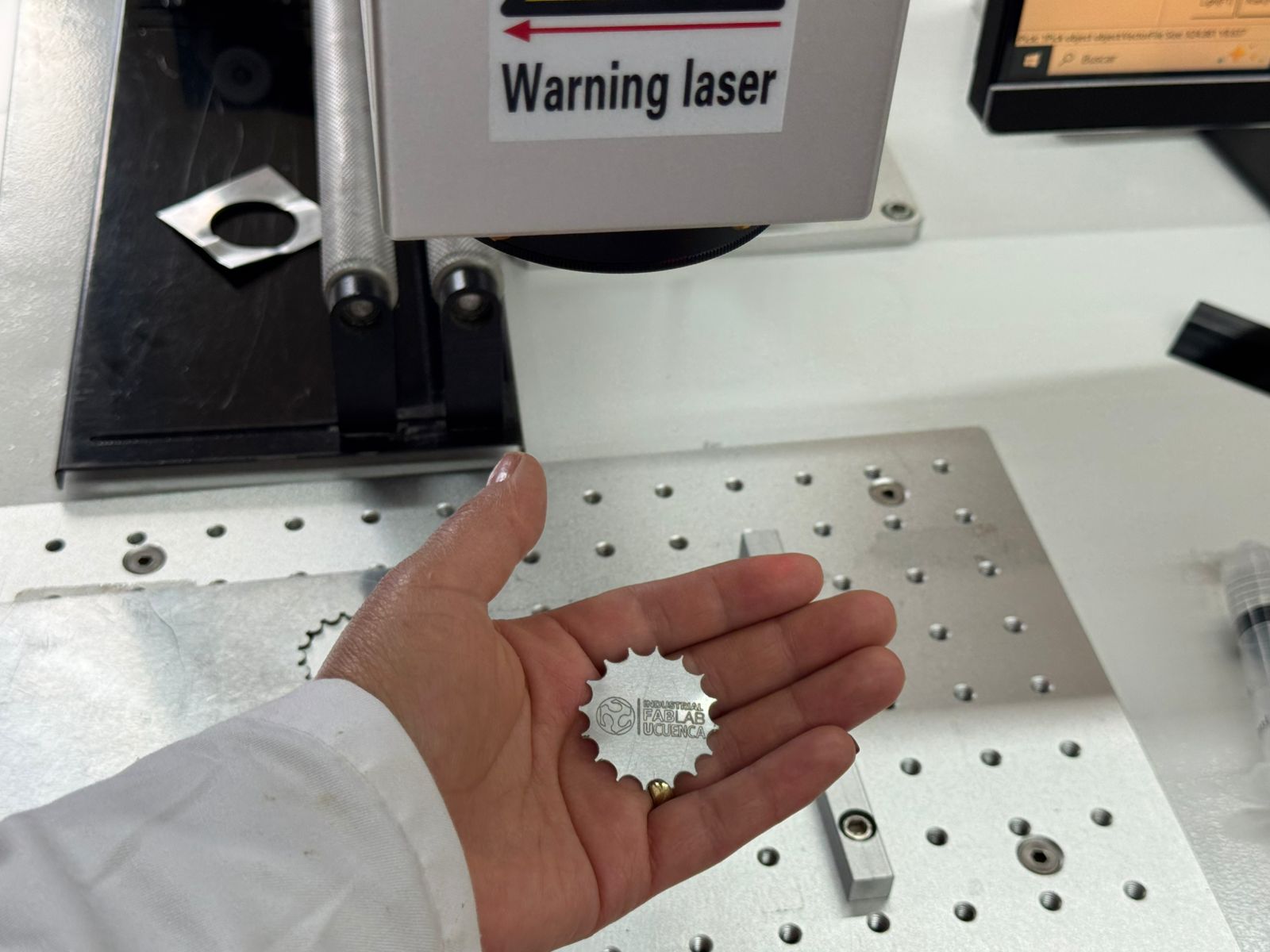
Hero Shot
The final hero shot shows the aluminum keychain after the cutting passes were completed and the piece was removed from the sheet. At this point I could evaluate the full result: the gear-shaped perimeter, the engraved FabLab UCuenca logo, the contrast of the fiber laser mark, and the scale of the object as a small metal keychain.
Download
The Fusion 360 file used for the aluminum keychain is available here:
Reflection
This wildcard experiment helped me understand how fiber laser machining expands the possibilities of digital fabrication. The process was different from the other Fab Academy weeks because the material, laser type, safety conditions, and number of passes all changed the way I had to think about manufacturing. The most important result was proving that the design could move from Fusion 360 to a metal fabrication workflow and that the aluminum part could be released after 50 cutting passes.