Group Assignment
The group assignment was the development of an automated conveyor belt machine that integrates mechanism, actuation, automation, function, and user interface. The official group documentation includes the complete machine description, team process, slide, and final demonstration video.
Open group assignment page
Individual Assignment - PCB Construction
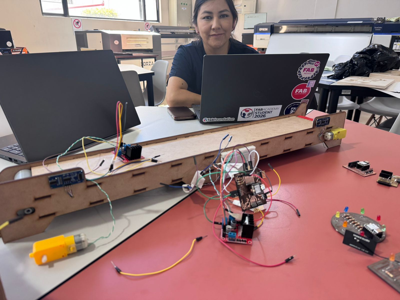
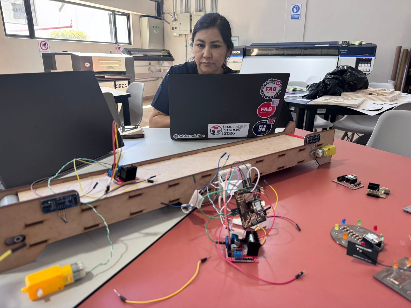
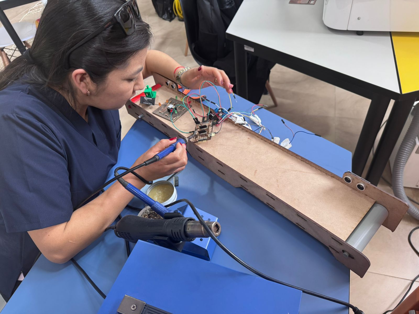
My individual work started with the construction of the custom PCB used to organize the electronic connections of the conveyor belt machine. The board was prepared for the XIAO ESP32-C3, the sensor headers, power lines, and connection points required for the control system.
The PCB helped reduce loose wiring during the machine integration stage and made the system easier to connect, test, and document. After fabrication, I checked the copper paths, cleaned the board, and prepared the headers for soldering.
Soldering Components
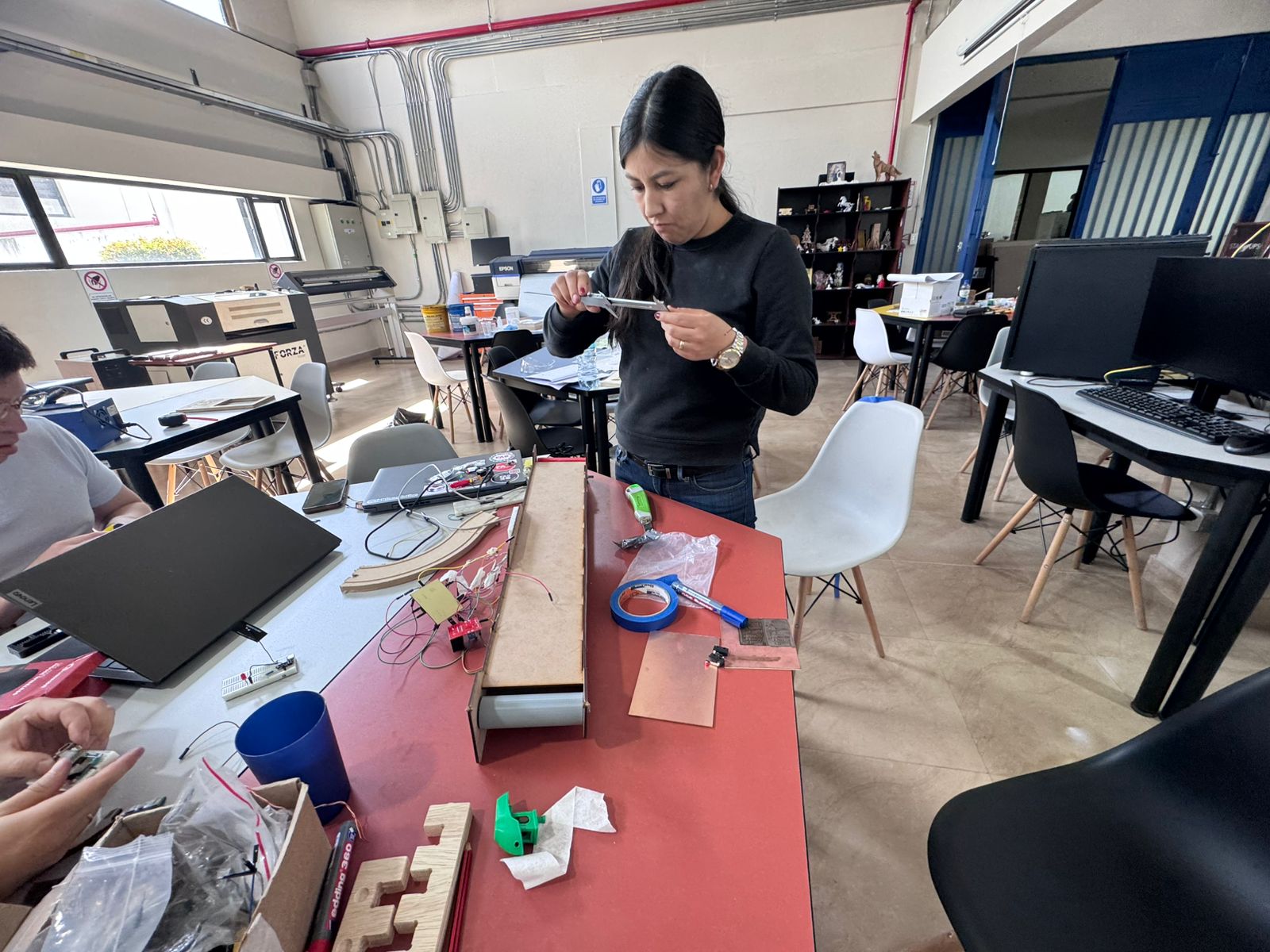
After preparing the PCB, I soldered the headers and electronic components needed to connect the microcontroller, sensors, and power lines. I used solder wire, flux, and a soldering station to create stable joints and avoid intermittent connections during the machine tests.
Each connection was visually inspected after soldering. The objective was to keep the board mechanically strong, electrically continuous, and ready for repeated connection and disconnection during assembly.
Sensor Connections
The conveyor belt uses ultrasonic sensors to detect the presence and position of the object. I connected the sensor wiring to the PCB and organized the signal, voltage, and ground lines so the controller could read the inputs during the automated cycle.
The sensor connections were checked before testing because the machine depends on reliable readings: one sensor starts the belt when an object is detected, and the second sensor stops the motor when the object reaches the end of the conveyor.
Connection workflow
- Identified the sensor pins for VCC, GND, TRIG, and ECHO.
- Connected the sensor lines to the PCB headers and the XIAO ESP32-C3 pins.
- Organized the wiring to keep the moving belt area clear.
- Verified the connections before running the machine test.
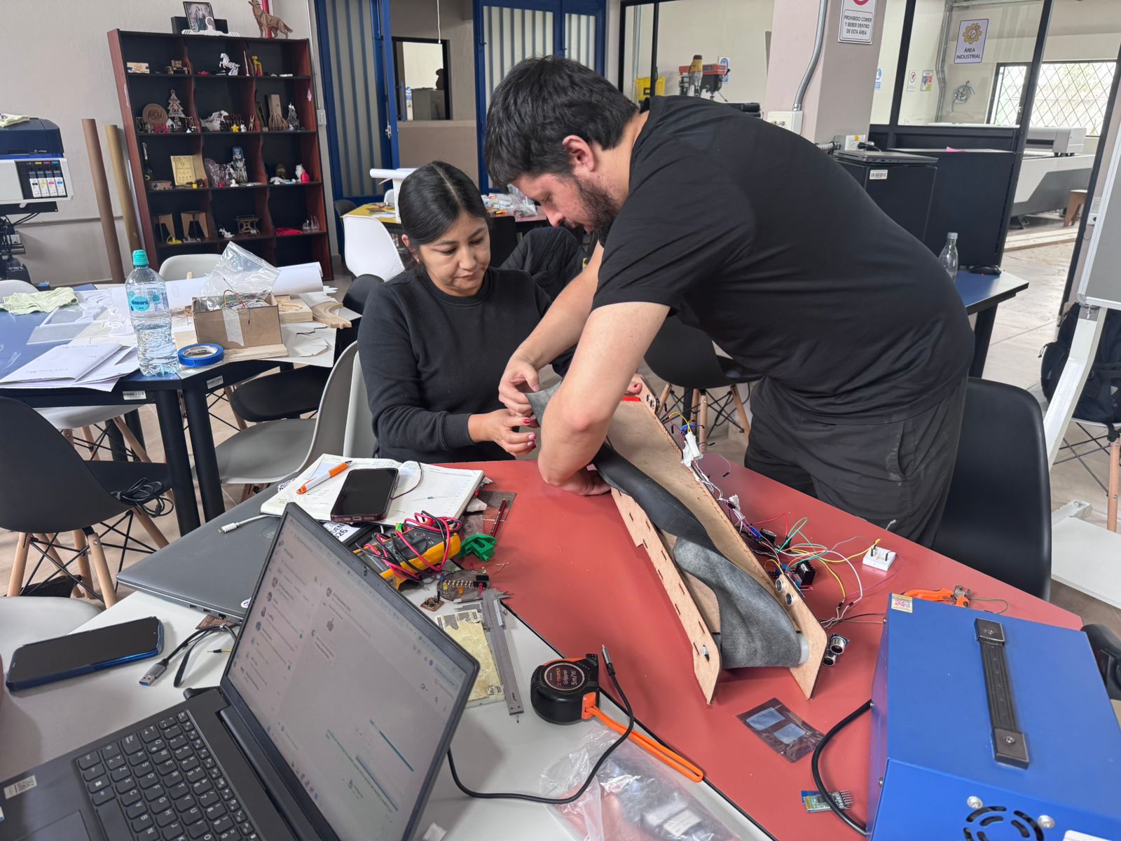
Machine Assembly
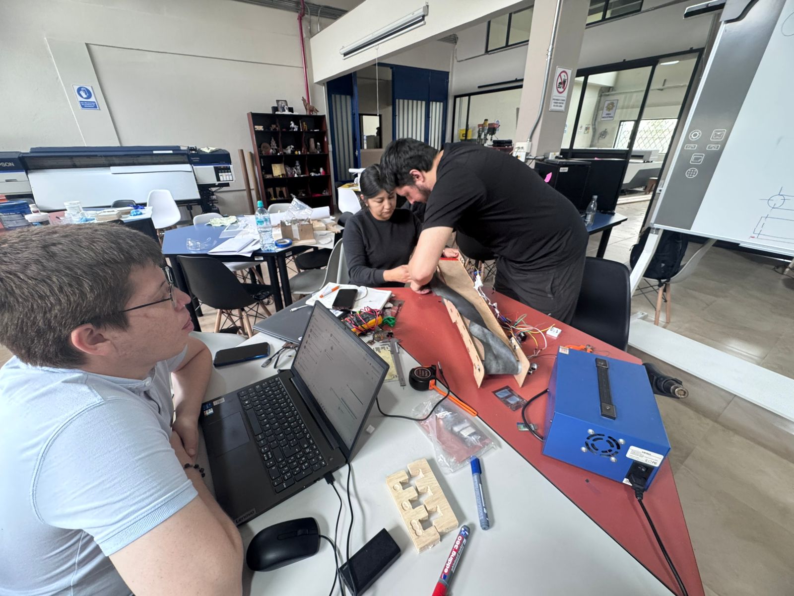
For the assembly stage, I worked on integrating the PCB, the sensors, the motor connections, and the wiring into the conveyor belt structure. This required checking the physical position of the electronics, keeping the cables organized, and making sure the components did not interfere with the belt movement.
The final assembly combined the fabricated structure with the electronic control system. After placing the components, the machine was prepared for group testing and validation.
Individual Reflection
This assignment helped me understand how important electronic integration is inside a machine project. The PCB was not only a board for making connections; it became a way to organize the system, reduce loose wires, and make the conveyor belt easier to test with the sensors and motor.
The most valuable part of my work was connecting the fabrication process with the final assembly. Soldering the components, checking the sensor wiring, and placing the electronics on the structure showed me that a machine depends on many small details working together. A weak solder joint, a loose connector, or a cable placed in the wrong position can affect the complete system.
Through this process I improved my confidence in PCB assembly, sensor wiring, and collaborative machine integration. I also learned that documenting each stage with photos and videos makes the final result easier to explain and helps identify what was tested, corrected, and validated.