WEEK 07 – Computer-Controlled Machining
Group Assignment
Computer-Controlled Machining
This assignment focuses on understanding and applying CNC machining processes, including safety training, machine characterization, and fabrication using computer-controlled tools.
Objectives
- Complete lab safety training.
- Test runout, alignment, fixturing, speeds, feeds, materials, and toolpaths.
- Document the process in the group page.
- Reflect on individual learning outcomes.
Individual Assignment
Large-Scale CNC Design and Fabrication Process
The objective of this individual assignment was to design and fabricate a large object using a CNC machine. The work involved CAD design, parametric modeling, material thickness definition, dogbone joint preparation, CAM setup, CNC machining, post-processing, assembly, and final validation.
The assignment was developed through an iterative process. First, a four-legged table was designed in Fusion 360 to understand parametrization, press-fit joints, material thickness, and dogbone generation. Then, a round table and a bench were fabricated using the CNC router. After reviewing the Fab Academy size requirement, the documentation was improved by preparing a corrected large-format design in Fusion 360 using a 1200 mm × 1200 mm board reference and a nested layout of approximately 1000 mm × 1000 mm.
1. Individual Assignment Overview
This assignment documents the complete learning process developed during Computer-Controlled Machining. The first stage focused on designing a four-legged table in Fusion 360. This exercise helped me understand how parametric CAD, material thickness, tolerances, press-fit joints, and dogbone geometry are related to CNC fabrication.
After the design exploration stage, a round table and a bench were fabricated using the CNC router. These objects allowed me to practice material fixation, CAM preparation, toolpath verification, cutting, post-processing, and physical assembly.
During the documentation review, I identified that the page did not clearly demonstrate the required large-format scale. To address this observation, I corrected the documentation by adding a Fusion 360 design reference with a board size of 1200 mm × 1200 mm and a nested design area of approximately 1000 mm × 1000 mm, following the Fab Academy requirement.
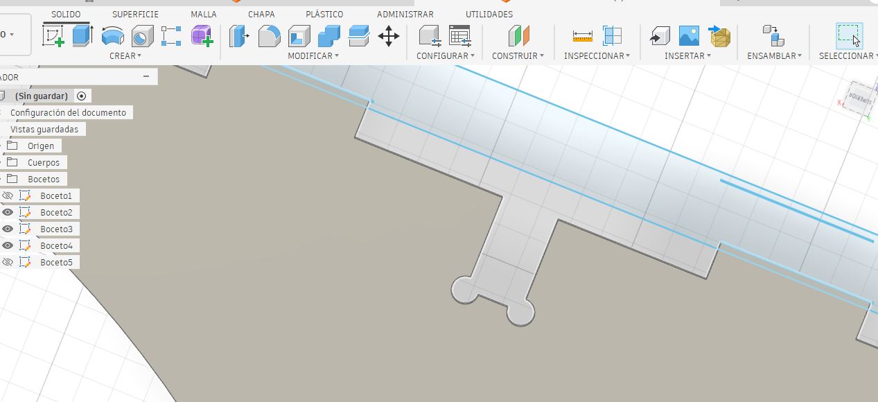
2. Initial Four-Legged Table Design in Fusion 360
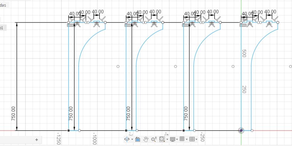
The first design exercise was a four-legged table modeled in Fusion 360. This design was used to explore the relationship between parametric modeling, material thickness, slot dimensions, joint tolerance, and CNC machining limitations.
The main purpose of this stage was to understand the construction logic required for CNC fabrication. The design included press-fit slots and dogbone joints to compensate for the circular geometry of the milling tool, since CNC routers cannot produce perfectly square internal corners.
Parametric CAD
Material thickness and dimensions were controlled in Fusion 360.
Press-fit Slots
The joints were designed according to plywood thickness.
Dogbones
Internal corners were adapted for CNC machining.
Assembly Check
The object was reviewed virtually before fabrication.
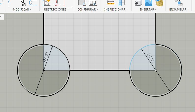
3. Parametrization, Material Thickness, and Dogbones
The Fusion 360 design was prepared using plywood as the reference material. The material thickness was an important parameter because the press-fit slots depend directly on the real thickness of the board.
| Design Parameter | Value / Description |
|---|---|
| Software | Fusion 360 |
| Material | Plywood |
| Nominal Thickness | 15 mm |
| Joint Tolerance | 0.2 mm |
| Assembly Type | Press-fit |
| Dogbone Purpose | Allow square parts to fit despite the circular CNC tool diameter. |
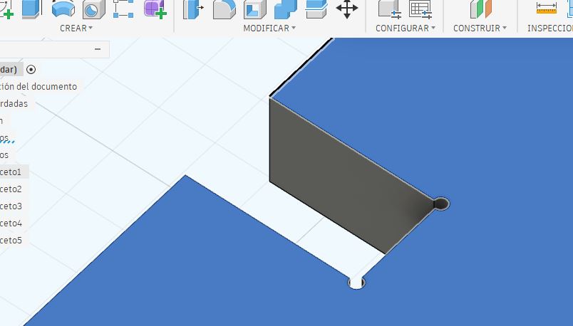
Because CNC milling tools are circular, internal corners cannot be cut perfectly square. For this reason, dogbone joints were added to the internal slot corners. This design decision improved assembly feasibility and reduced interference between the milling tool radius and the press-fit joints.
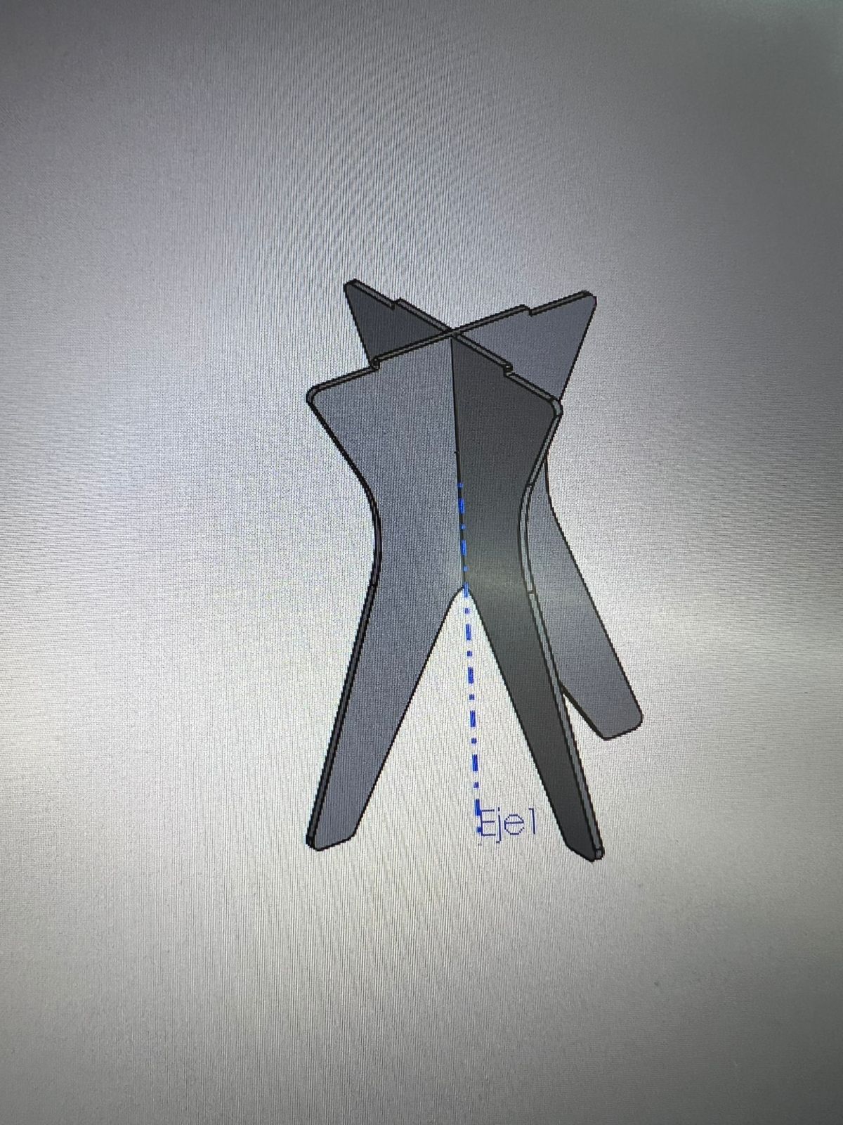
4. Bench Design in Fusion 360
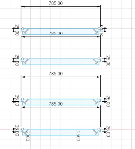
In addition to the initial table exercise, a bench was also designed in Fusion 360 to evaluate another type of press-fit structure. This design helped me analyze geometry, structural behavior, assembly logic, and the relationship between vertical supports and the upper surface.
The bench design was useful for understanding how different pieces can intersect and support each other using only CNC-cut slots and press-fit connections.
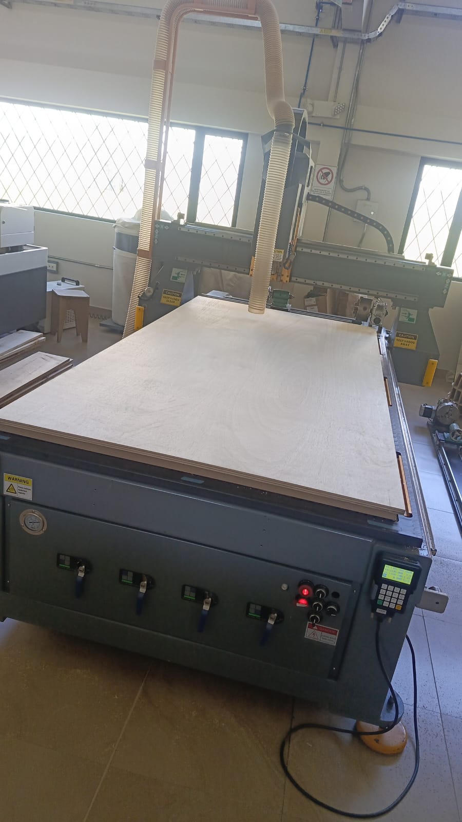
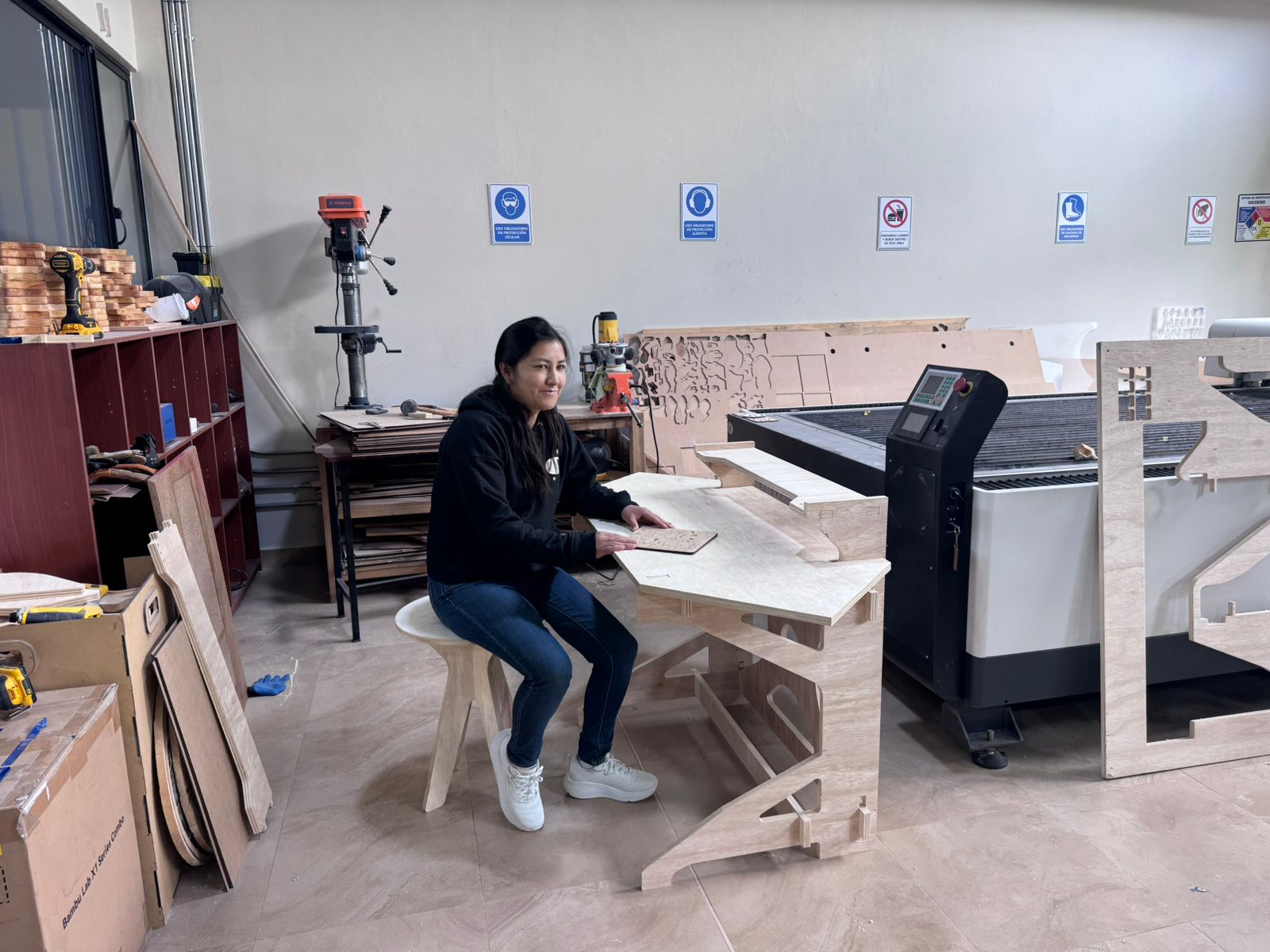
5. CNC Fabrication Evidence
After completing the design tests, the CNC router was used to fabricate the parts in plywood. The fabrication process allowed me to apply the complete CNC workflow, including material fixation, CAM preparation, toolpath verification, machining, post-processing, and assembly.
The CNC fabrication process helped validate important concepts such as plywood behavior, press-fit tolerances, dogbone joints, cutting sequence, tab removal, and assembly limitations.
| Fabrication Aspect | Description |
|---|---|
| Material | Plywood |
| Fabrication process | Large-format CNC routing |
| Assembly method | Press-fit joints |
| Learning outcome | Toolpath preparation, material fixation, cutting, and assembly validation |
6. Documentation Issue Identified After Review
After reviewing the Fab Academy Computer-Controlled Machining requirement, I identified that my documentation did not clearly demonstrate the required large-format scale. Although the design and fabrication process demonstrated important CNC machining skills, the page needed stronger evidence of the minimum board size and the approximate nested design area.
Fab Academy specifies that the board used for this assignment should be at least 4 ft × 4 ft, equivalent to approximately 1200 mm × 1200 mm, and that the nested parts should occupy roughly 1 m × 1 m. This requirement ensures that the assignment demonstrates safe CNC machining techniques at a large scale, rather than small-scale prototyping.
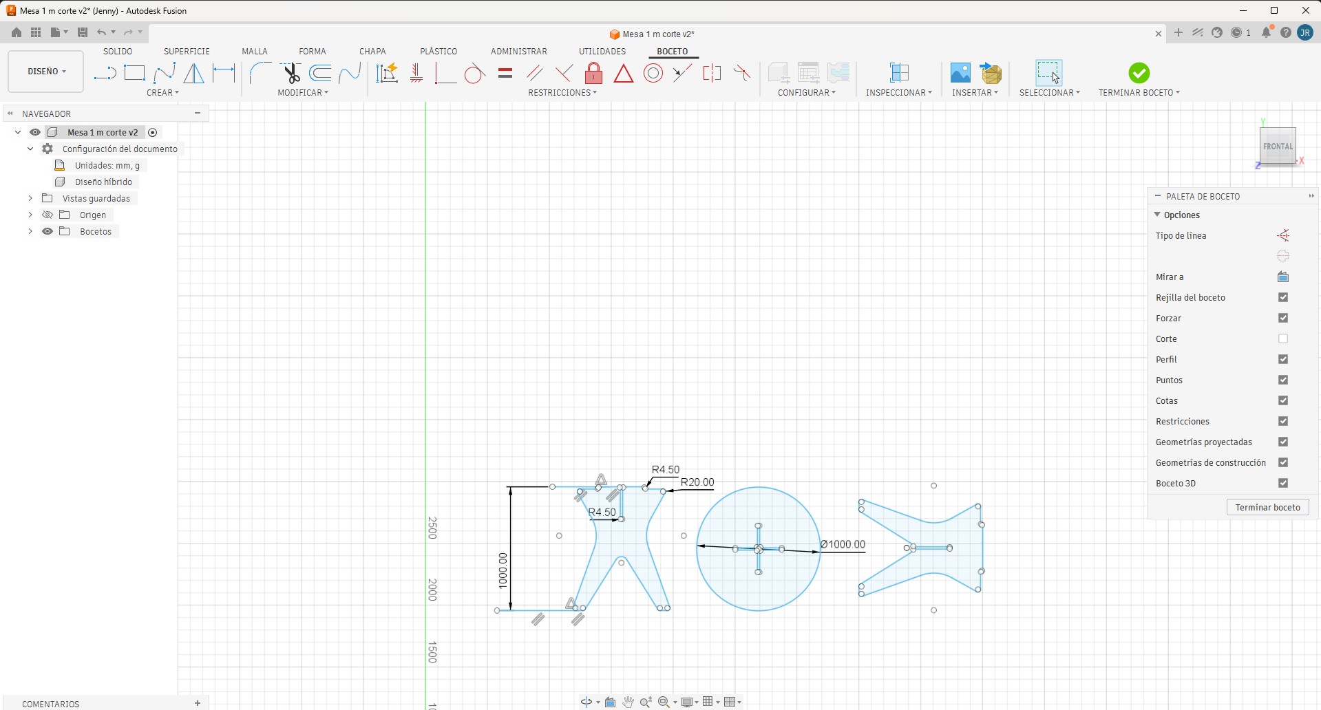
7. Corrected Large-Format Fusion 360 Design
To address the evaluation observation, I prepared a corrected large-format design reference in Fusion 360. This correction was developed using the recommended dimensions for the Computer-Controlled Machining assignment.
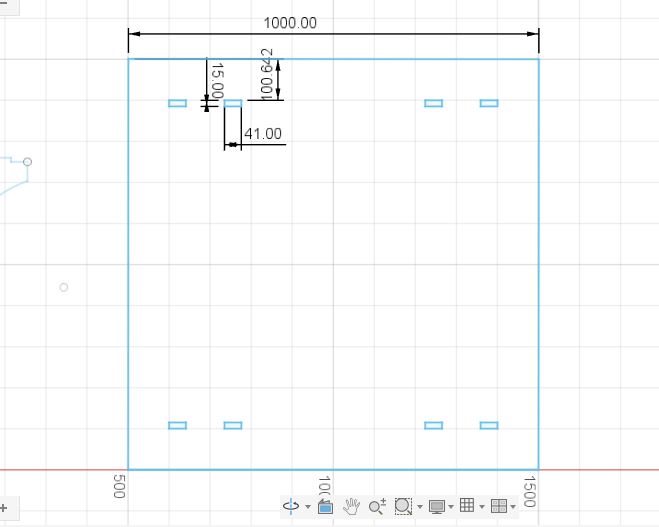
The corrected Fusion 360 design was prepared considering a plywood board of 1200 mm × 1200 mm, with the main parts arranged to occupy approximately 1000 mm × 1000 mm. This correction clearly shows that the assignment corresponds to a large-format CNC object and not to a small-scale prototype.
| Fab Academy Requirement | Corrected Design Value | Status |
|---|---|---|
| Minimum board size | 1200 mm × 1200 mm | Completed |
| Approximate nested design area | 1000 mm × 1000 mm | Completed |
| Software used for correction | Fusion 360 | Completed |
| Purpose | Verify the required large-format scale | Completed |
8. Large Format Requirement Verification
This verification demonstrates that the corrected documentation satisfies the expected scale for the assignment and provides a clear basis for CNC machining planning, including material handling, fixturing, toolpath generation, and safe operation.
| Verification Item | Required by Fab Academy | Corrected Documentation |
|---|---|---|
| Board size | At least 4 ft × 4 ft / 1200 mm × 1200 mm | 1200 mm × 1200 mm reference |
| Nested design scale | Roughly 1 m × 1 m | Approximately 1000 mm × 1000 mm |
| Software | CAD design software | Fusion 360 |
| Purpose | Demonstrate safe CNC machining at a large scale | Design correction and CNC workflow documentation |
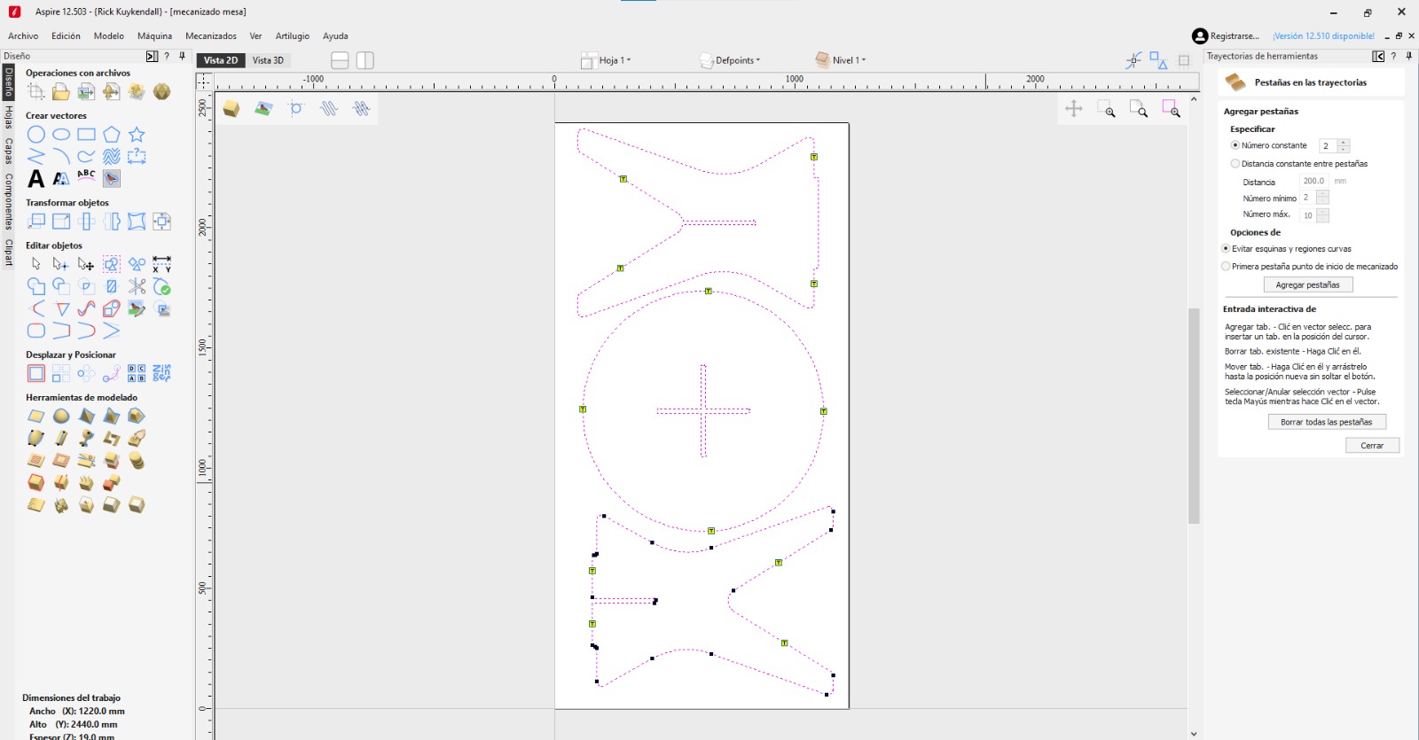
9. CAM Preparation and CNC Machining Workflow
Aspire software was used to prepare and review the CNC machining workflow. This stage included checking the layout, toolpaths, cutting sequence, tabs, and machining strategy before running the CNC job.
Before machining, the material thickness, tool diameter, cutting depth, joint tolerance, and dogbone clearances were reviewed. These parameters are important because small errors in large-format machining can affect the fit of the press-fit joints and the final stability of the object.
| Machining Parameter | Value / Description |
|---|---|
| Machine Type | Large-format CNC router |
| Material | Plywood |
| Material Thickness | 15 mm |
| Tool Type | 6 mm universal end mill |
| Joint Clearance | 0.2 mm |
| Dogbone Purpose | Compensate for the circular tool in internal corners |
| Material Fixation | Plywood fixed to the CNC bed before cutting |
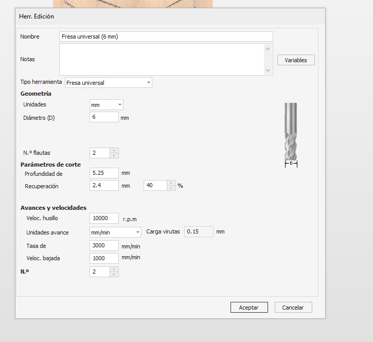
Feeds, Speeds, and Tool Configuration
The following numerical machining parameters were used for the CNC cutting process. These values were taken from the Aspire tool configuration for the 6 mm universal end mill.
| Parameter | Value Used | Unit |
|---|---|---|
| Tool name | Fresa universal | 6 mm |
| Tool diameter | 6 | mm |
| Number of flutes | 2 | - |
| Cut depth / pass depth | 5.25 | mm |
| Stepover | 2.4 | mm |
| Stepover percentage | 40 | % |
| Spindle speed | 10000 | RPM |
| Feed rate | 3000 | mm/min |
| Plunge rate | 1000 | mm/min |
| Chip load | 0.15 | mm |
10. Post-processing and Part Removal
After the CNC cutting process, the parts were carefully removed from the plywood sheet. This step was important to avoid damaging the press-fit joints and to verify that the toolpaths, tabs, and cutting depth were correctly prepared.
Removing the CNC-cut parts from the plywood sheet after machining.
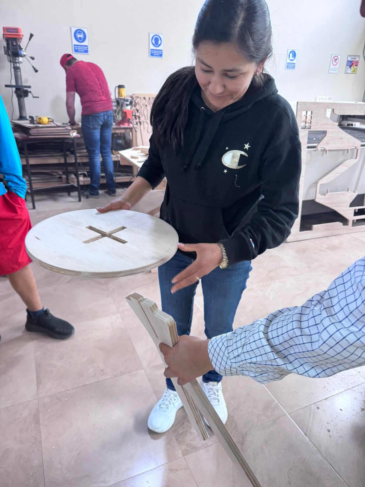
11. Physical Assembly and Validation
After CNC machining, the parts were removed from the plywood sheet, tabs were cleaned, and the joints were tested. The physical assembly process helped verify whether the selected tolerance worked correctly and whether the parts could be assembled without screws or glue.
The press-fit system demonstrated the relationship between CAD tolerances, material thickness, CNC cutting quality, and assembly performance.
- Parts were removed from the plywood sheet after machining.
- Tabs were cleaned and edges were post-processed.
- Press-fit joints were tested during assembly.
- The final object demonstrated CNC fabrication and assembly learning outcomes.
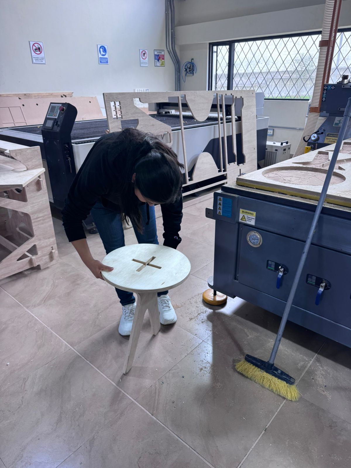
12. Final CNC Fabricated Object and Corrected Table Design
The CNC-manufactured object was fabricated using plywood, parametric design methodologies, dogbone joints, and press-fit assembly systems. This fabrication exercise helped demonstrate CNC machining skills, including cutting preparation, material fixation, post-processing, and assembly.
The final result was documented using video evidence to show the object after machining, post-processing, and assembly.
The Fusion 360 correction was also added to clearly document the required large-format size and to align the assignment with the expected Fab Academy scale for Computer-Controlled Machining.
Final CNC-fabricated object after machining, post-processing, and assembly.
13. Downloadable Files
The following files correspond to the design and fabrication resources developed during this assignment. They include the Fusion 360 design files and DXF cutting files used during the CNC workflow.
14. Final Reflection
This assignment helped me understand the complete workflow of large-scale CNC fabrication. The process included parametric design, material thickness definition, dogbone joint preparation, CAM setup, CNC machining, post-processing, assembly, and documentation correction.
The first four-legged table design in Fusion 360 was useful for understanding parametrization, press-fit logic, material thickness, and dogbone geometry. The CNC fabrication process allowed me to practice real machining, material fixation, cutting preparation, and physical assembly.
The review process also helped me identify an important documentation issue: the page did not clearly prove the required large-format size. This was an important learning point because Computer-Controlled Machining is not only about cutting a design, but also about demonstrating the correct scale, safe machining practices, and appropriate material handling.
To correct this, I prepared a Fusion 360 design reference using a 1200 mm × 1200 mm board and a nested layout of approximately 1000 mm × 1000 mm. This correction directly addresses the Fab Academy requirement and confirms that the assignment meets the expected scale for large-format CNC machining.
Overall, this week reinforced the importance of iterative design, tolerance calibration, dogbone geometry, CAM preparation, CNC safety, physical assembly, and clear technical documentation within the Fab Academy digital fabrication workflow.