Week 07 - Computer-Controlled Machining
CNC Router Safety Training, Machine Characterization and Press-Fit Tolerance Testing
Personal Contributions
| Name | University | Activities carried out |
|---|---|---|
| Rodrigo Guamán | Universidad de Cuenca |
|
| Jenny Rojas | Universidad de Cuenca |
|
| Diego Zhindón | Universidad Politécnica Salesiana |
|
Group Assignment - Lab Safety Training and CNC Characterization
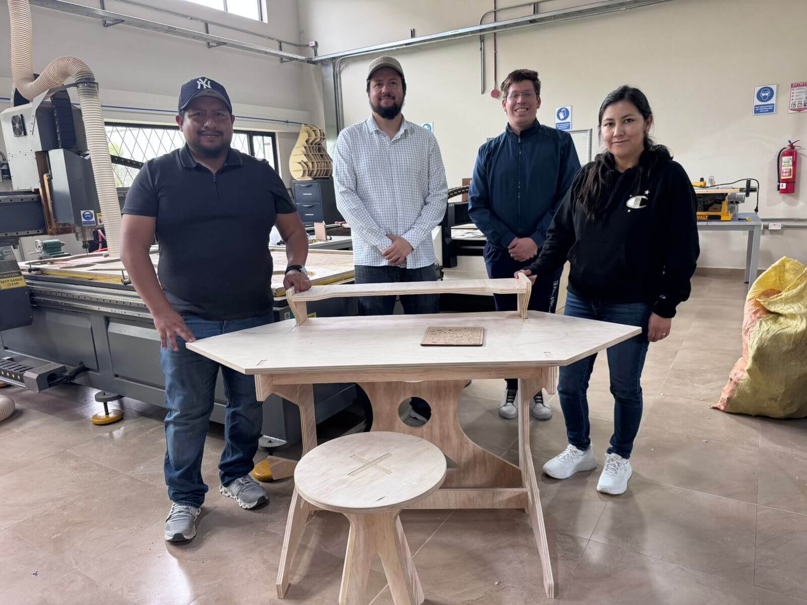
The group assignment for this week was developed at START LABS, located at the Universidad Politécnica Salesiana. The work was carried out collaboratively with the team members Jenny Rojas, Rodrigo Guamán, and Diego Zhindón, under the guidance of Roberto Gallo from ZOI Lab. The assignment focused on the CNC router used for computer-controlled machining.
Assignment Requirements
- Complete the lab's safety training before operating the CNC router.
- Test runout, alignment, fixturing, speeds, feeds, materials, and toolpaths for the machine.
- Document the group work page and reflect on the individual page about what was learned.

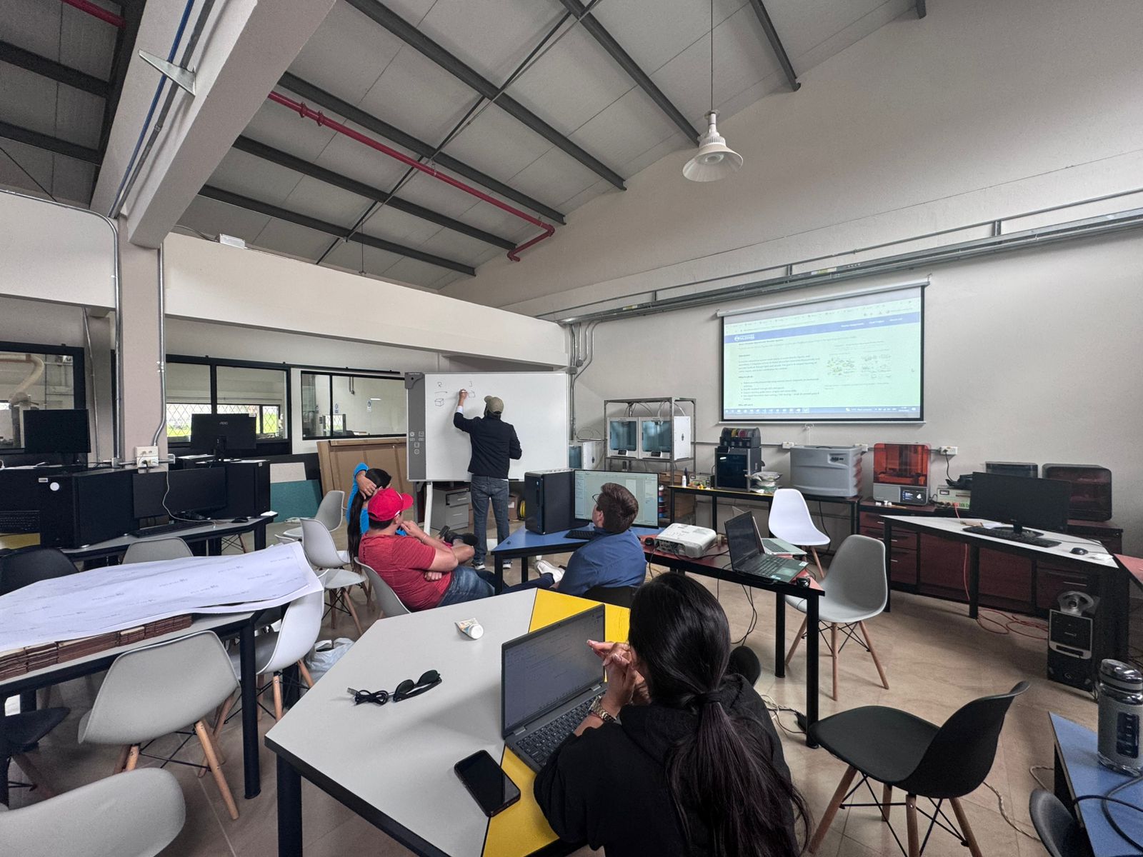
Lab Safety Training
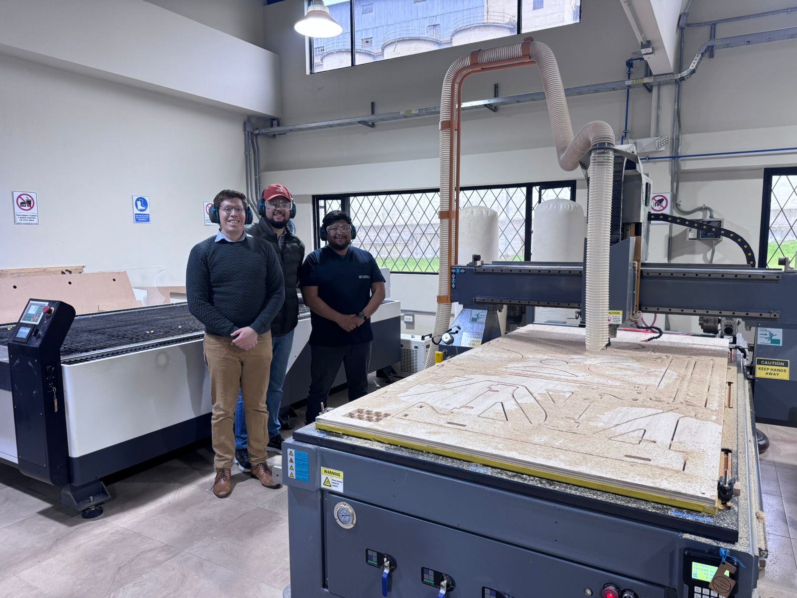
As a first step, the team completed the laboratory safety training for the CNC router. The training covered the correct use of the machine, the risks created by a rotating spindle, the importance of dust extraction, the correct way to secure plywood sheets, and the emergency procedures required before any cutting operation.
- Use safety glasses, hearing protection, dust mask or respirator, and closed safety footwear.
- Confirm that loose clothing, jewelry, cables, and long hair cannot reach the spindle or moving gantry.
- Locate the emergency stop button and verify that the operator knows when to use it.
- Check that the workpiece is fixed before running the toolpath.
- Keep the working area clean so dust and loose pieces do not interfere with the cutting path.
- Stay outside the machine envelope while the spindle is rotating.
Documentation and Reflection
The group work page documents the CNC router characterization, safety conditions, machine tests, tolerance samples, and observations. Each individual page should also reflect what was learned from safety training, toolpath setup, machine calibration, and the relationship between digital design and real machining behavior.
CNC Machine Characterization and Safety Requirements
Machine Characterization
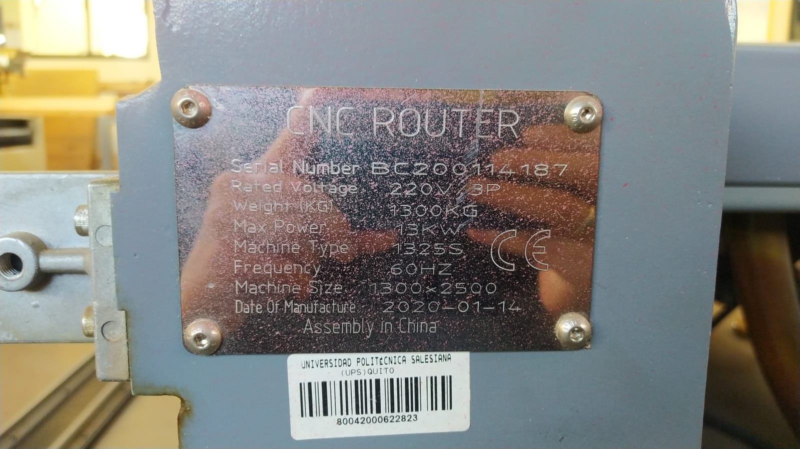
The CNC machine characterized for this assignment is a flatbed CNC router used for large-format machining operations in plywood and similar sheet materials. The characterization was based on the group machine review documented by Rodrigo Guamán and on the physical machine nameplate installed on the equipment at START LABS. The machine power supply is a critical requirement: according to the nameplate, it requires 220 V, 3-phase power at 60 Hz, with a maximum power of 13 kW.
| Parameter | Description |
|---|---|
| Machine Type | Flatbed CNC Router |
| Working Materials | Wood (plywood, MDF), plastics, composite materials |
| Working Area | Approximately 1200 x 2400 mm (4x8 ft format) |
| Cutting System | Rotary milling tool (end mill) |
| Axes | 3 axes (X, Y, Z) |
| Precision | +/-0.1 mm depending on calibration |
| Spindle Speed | 12,000 - 24,000 RPM (variable) |
| Tool Type | Flat end mill, ball nose, others |
| Fixation System | Vacuum bed or mechanical clamps |
| Software | Aspire / VCarve / CAM software |
| Input Formats | DXF, SVG, G-code |
| Dust Extraction | Integrated dust collection system |
| Operation Type | 2D, 2.5D cutting and engraving |
| Power Supply | 220 V, 3-phase industrial power supply, 60 Hz, maximum power 13 kW. This electrical requirement must be verified before operating the machine. |
| Additional nameplate and test details | |
| Rated Voltage | 220 V, 3-phase |
| Maximum Power | 13 kW |
| Machine Size | 1300 x 2500 mm |
| Machine Type Code | 1325S |
| Serial Number | BC202114187 |
| Frequency | 60 Hz |
| Weight | 1300 kg |
| Date of Manufacture | 2020-01-14 |
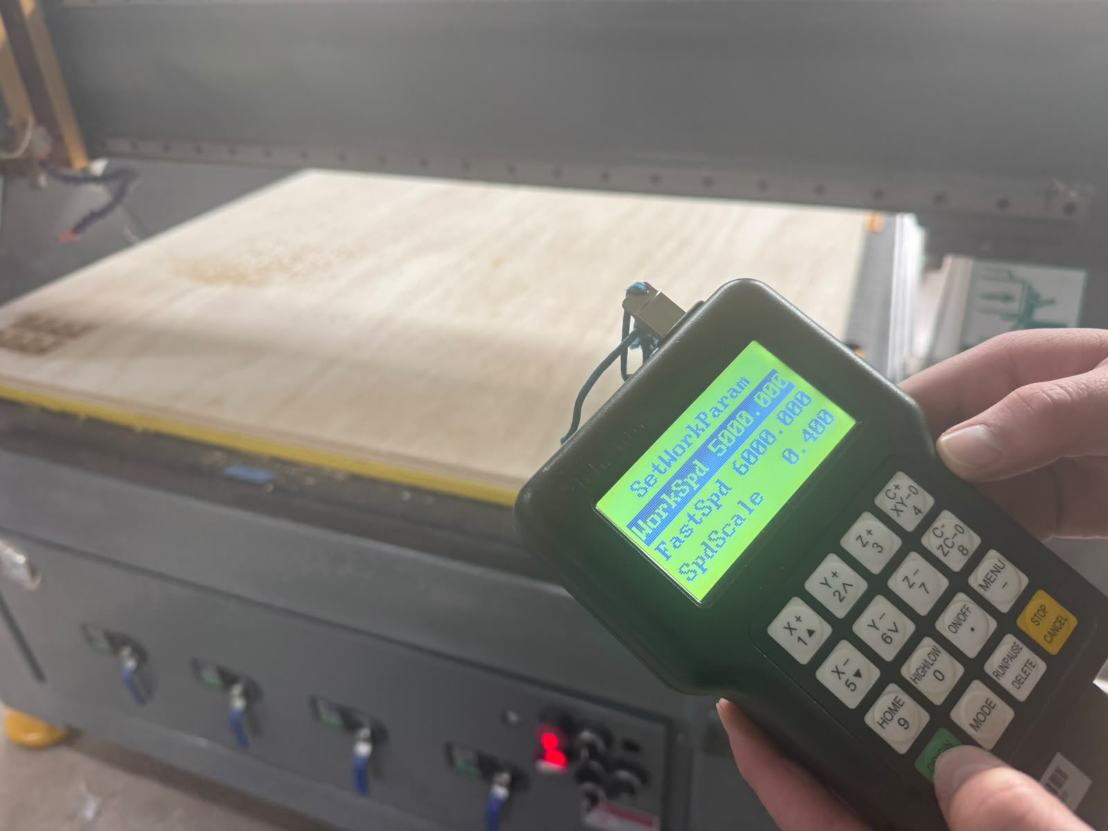
| Feed Rate Used in Test | 5000 mm/min normal feed |
| Fast Speed Used in Test | 6000 mm/min fast movement |
| Test Material | Plywood for press-fit tolerance testing |
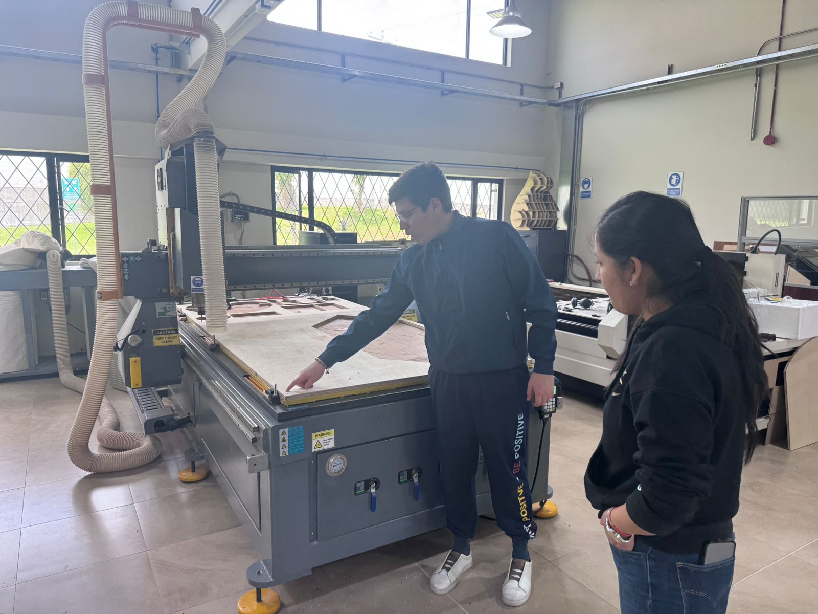
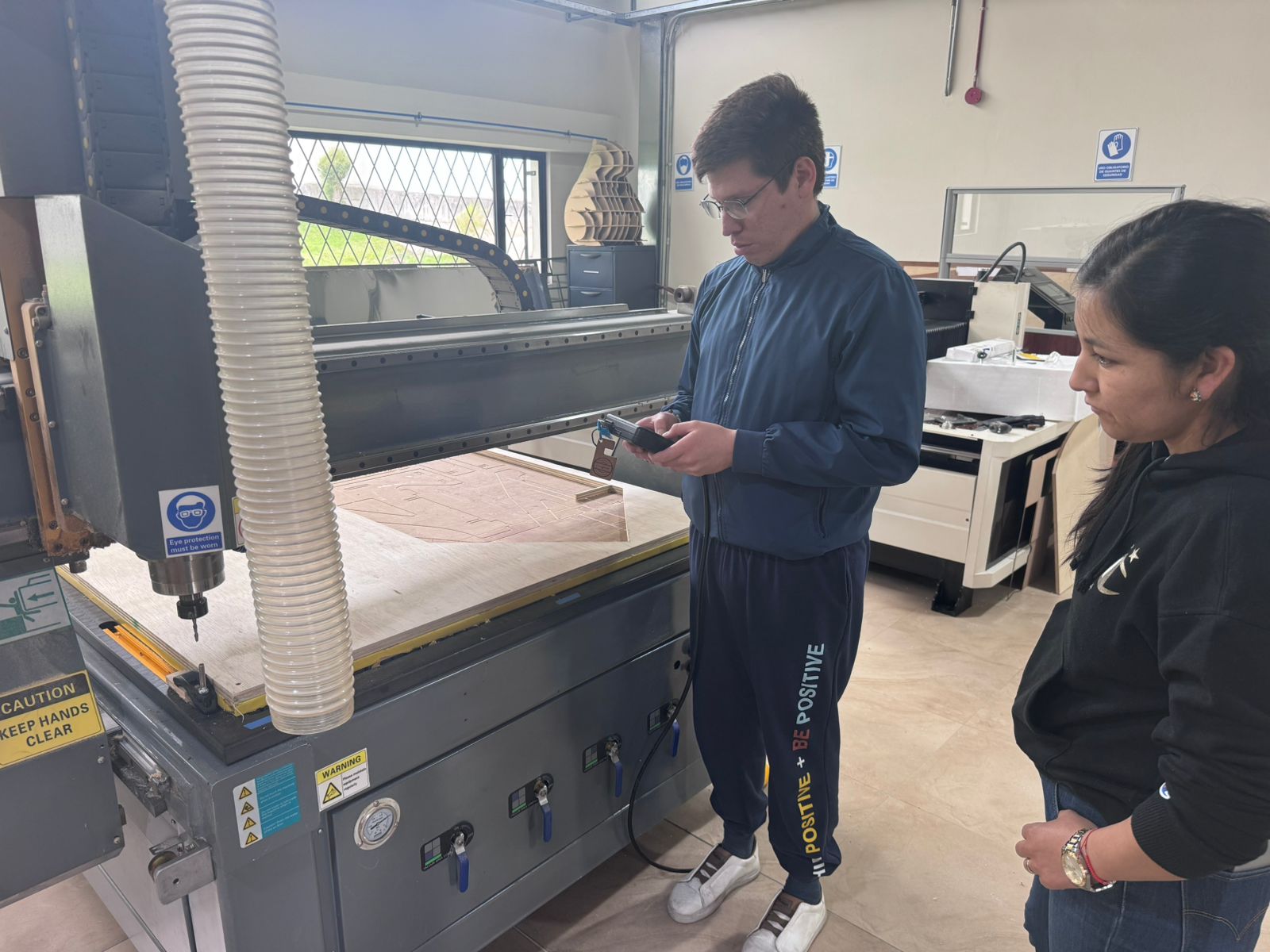
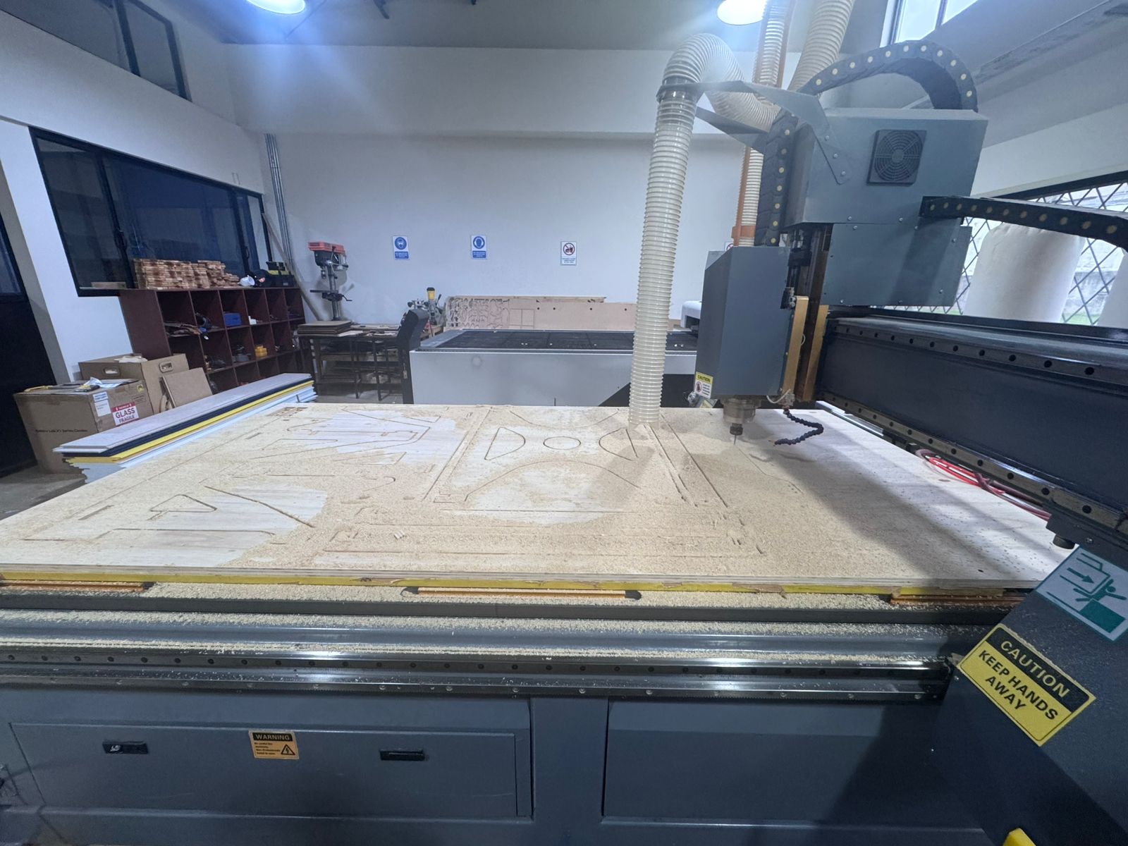
Machine Tests: Runout, Alignment, Fixturing, Speeds, Feeds, Materials and Toolpaths
The CNC router was tested by preparing plywood samples and checking the complete workflow from material fixation to toolpath execution. The goal was to understand how the machine behaves before fabricating larger press-fit structures.
| Test | Observation |
|---|---|
| Runout | The spindle and end mill were visually checked before cutting. Any vibration, eccentric rotation, or abnormal noise would require stopping and inspecting the tool. |
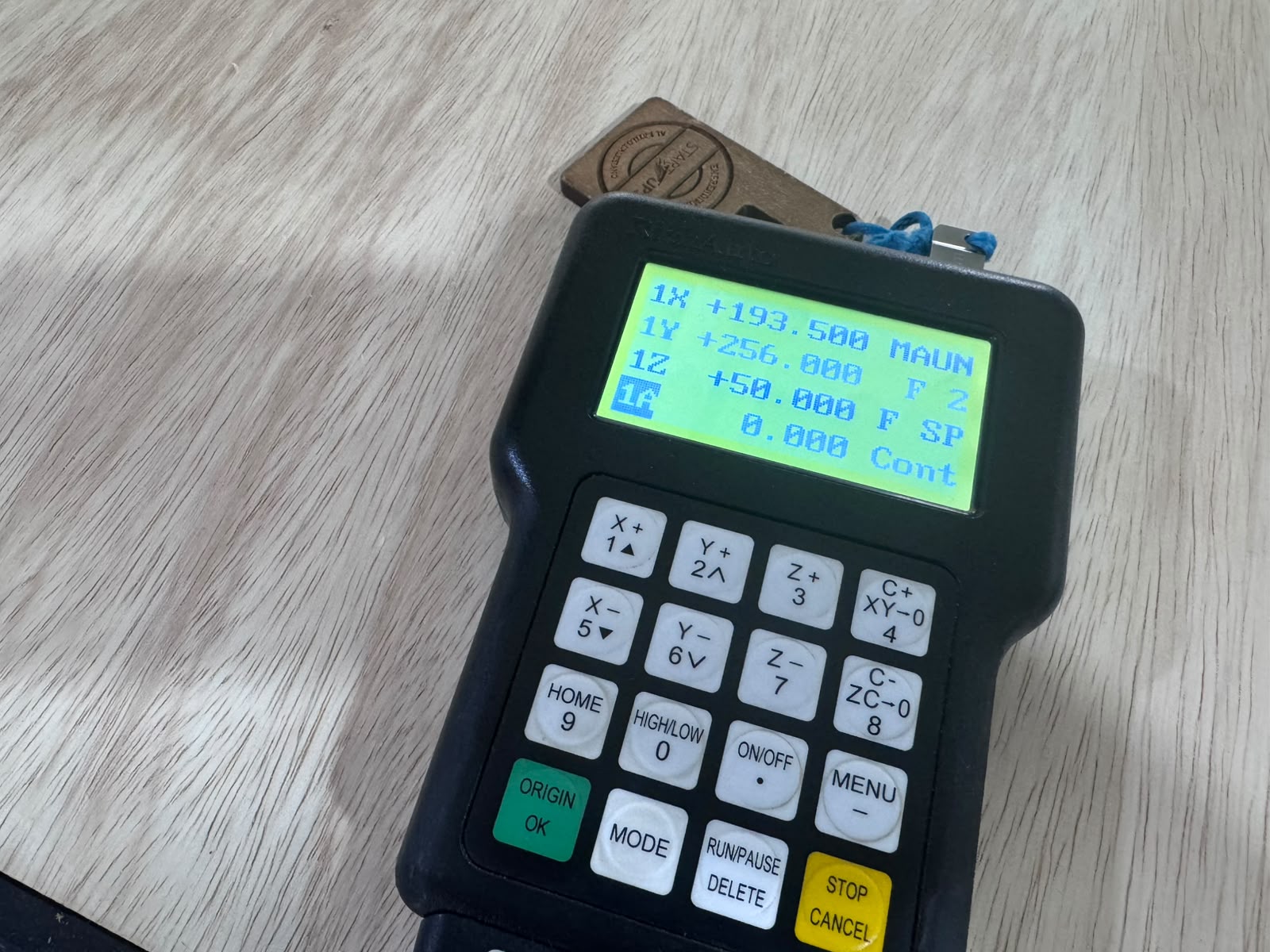
| Alignment | The X, Y, and Z axes were referenced with the handheld controller before starting the job. The origin was set on the plywood sheet after checking the usable work area. |
| Fixturing | The plywood sheet was positioned flat on the CNC bed and held securely to avoid movement during the cut. Fixation was checked before running the spindle. |
| Speeds and Feeds | The controller setup showed a normal feed of 5000 mm/min, fast speed of 6000 mm/min, and spindle value of 0.400 in the setup menu; the running screen showed X, Y, and Z coordinates during operation. |
| Materials | Plywood was used for press-fit tolerance testing. Because plywood thickness can vary, measurements were taken at different points of the board. |
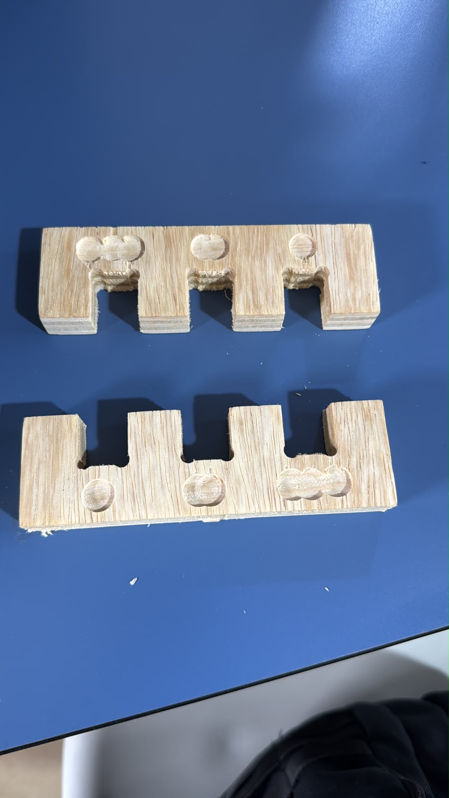
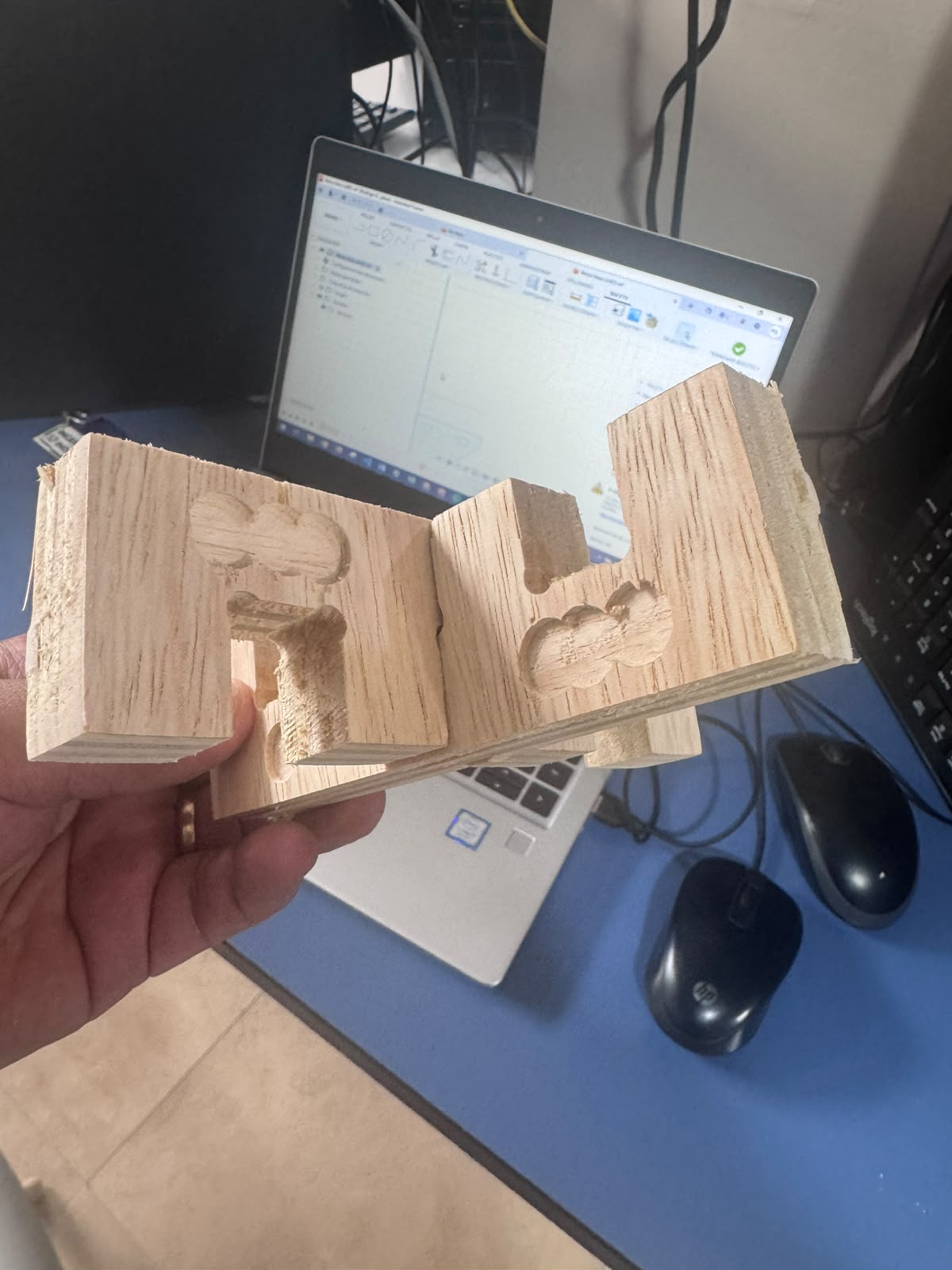
| Toolpaths | The toolpaths included profile cuts and pocket/dog-bone reliefs to evaluate joint clearance and assembly behavior. |
2. Tolerance Calculation
A base machining tolerance of 3 mm was considered as part of the CNC process constraints and tool behavior. However, for press-fit joints, more precise tolerances were required.
3. Press-Fit Tolerance Testing
- 0.3 mm
- 0.6 mm
- 0.9 mm
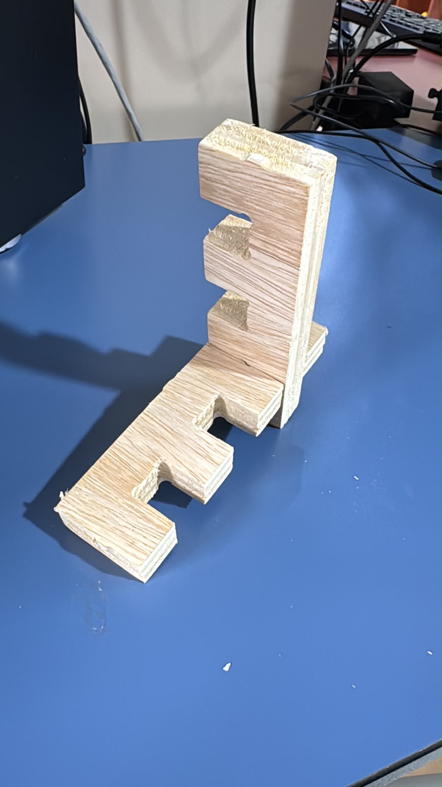
The test pieces were fabricated and evaluated physically. Measurements were taken from three different points across the plywood board to account for material inconsistencies.
The results showed that 0.3 mm tolerance provided the best press-fit, achieving a firm and stable joint without excessive force.
Safety Requirements and Conditions
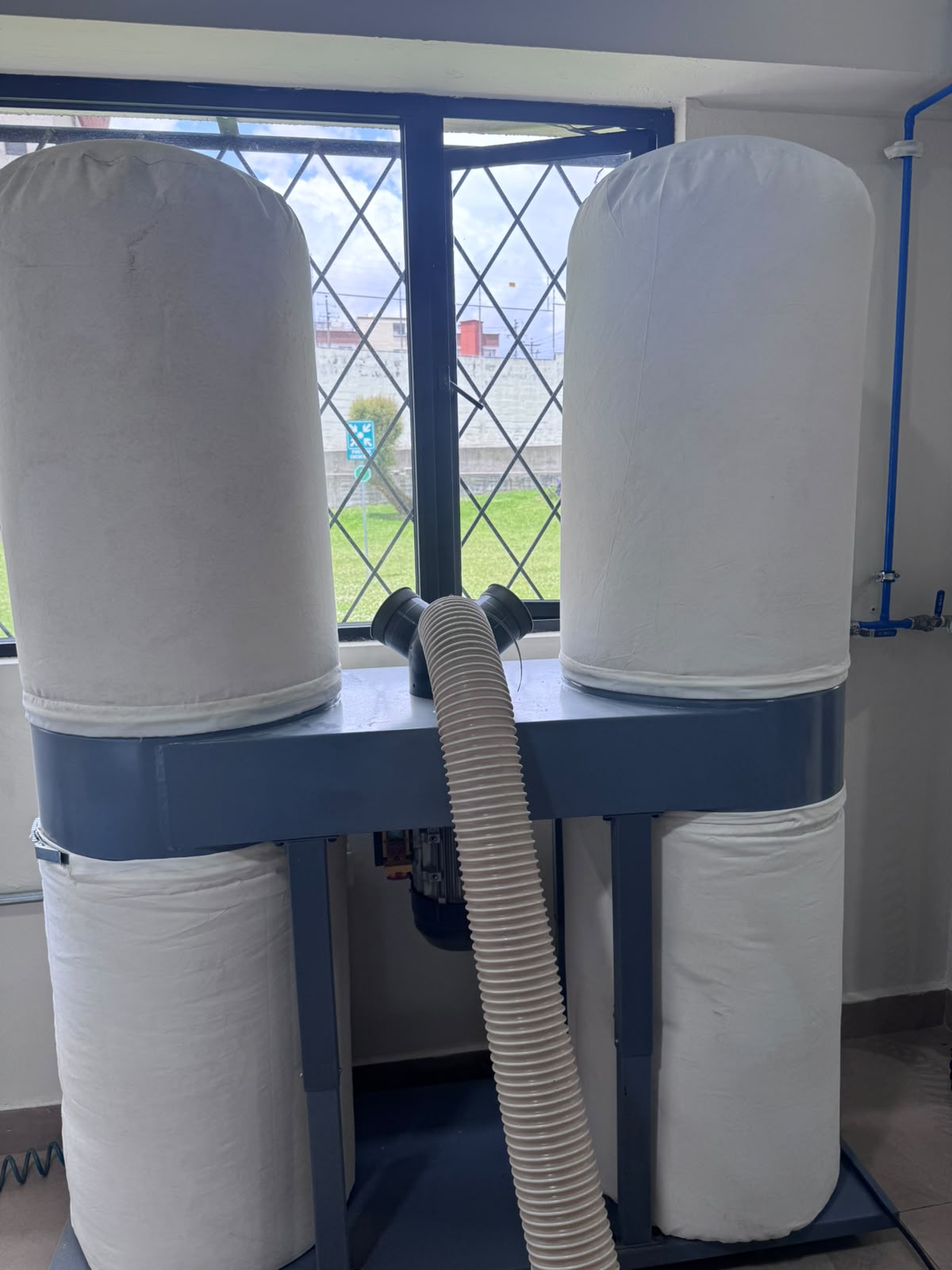
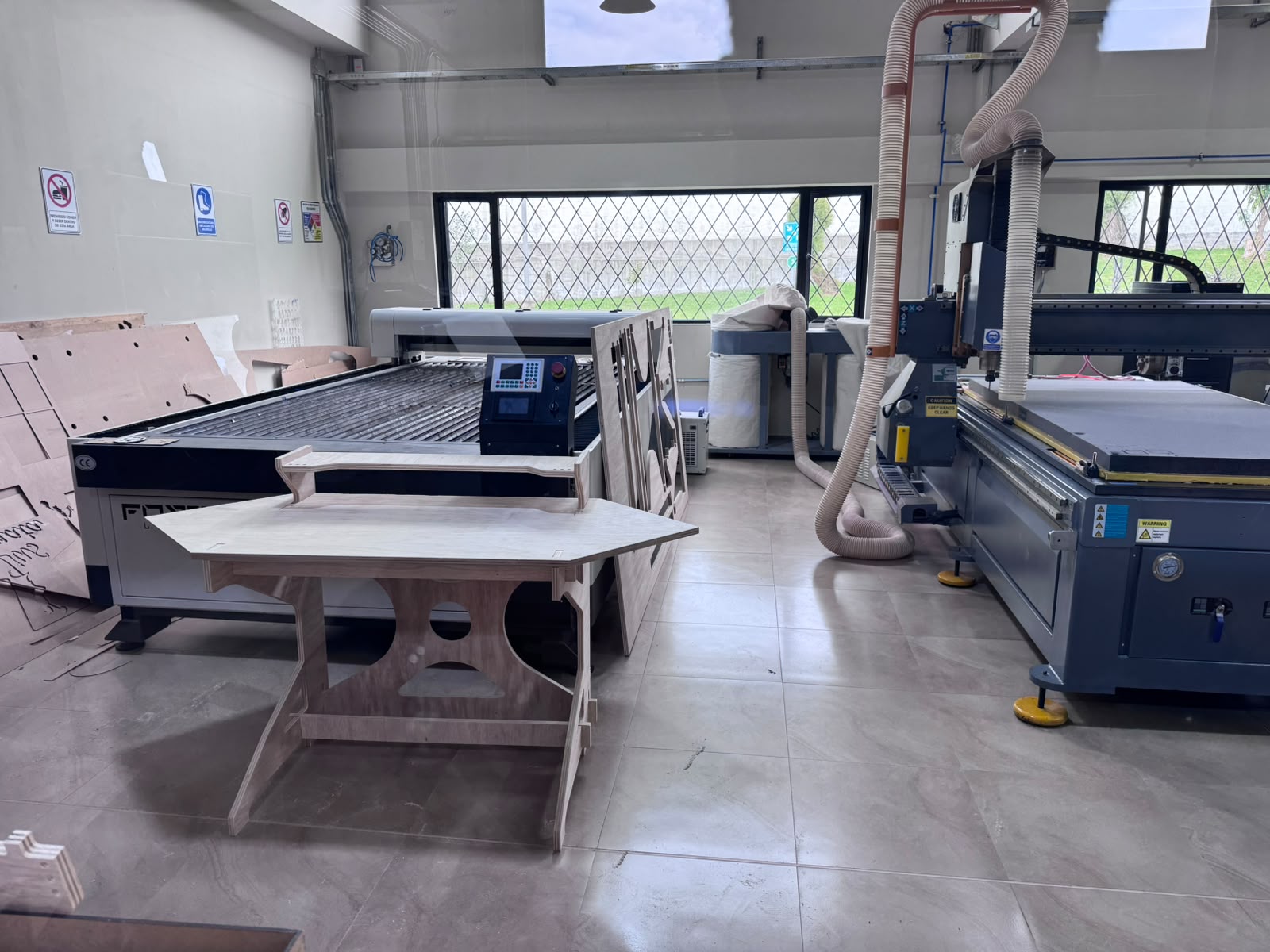
A CNC router produces chips, dust, and fine particulate matter while cutting plywood, MDF, and similar materials. For this reason, the machine must be operated with an active material and particulate extraction system. The extraction hose must be connected close to the spindle area, the collector bags must have enough capacity, and the airflow must be checked before machining. This condition is not optional: without extraction, dust can affect operator health, reduce visibility, contaminate the lab, increase cleaning time, and create additional fire or overheating risks.
Personal Protective Equipment (PPE)
- Safety glasses must be worn to protect the eyes from chips and dust.
- Hearing protection is required because the spindle and dust extraction system generate high noise levels.
- A dust mask or respirator must be used when cutting plywood, MDF, or other materials that generate fine particles.
- Closed safety footwear is required in the CNC area.
- Loose clothing, jewelry, and untied hair are not allowed near the moving gantry or spindle.
Before Operating
- Verify that the machine is connected to the required 220 V, 3-phase industrial power supply at 60 Hz before operation.
- Inspect the end mill and confirm that it is correctly installed and tightened.
- Verify that the plywood sheet is flat and firmly fixed to the bed.
- Set the X, Y, and Z origin carefully before running the job.
- Load the correct toolpath file and confirm the material thickness, tool diameter, feed rate, spindle speed, and cutting depth.
- Perform a dry run or simulation to confirm the toolpath stays inside the safe work area.
- Turn on and verify the dust and particulate extraction system before machining.
- Confirm that the extraction hose is connected, unobstructed, and positioned to collect material directly from the cutting area.
During Operation
- Keep hands and tools away from the cutting area while the spindle is rotating.
- Maintain a safe distance from the machine envelope.
- Monitor the process continuously and never leave the CNC router unattended.
- Check that chips and fine particles are being removed by the extraction system during the cut.
- Stop the job if abnormal vibration, tool noise, burning smell, smoke, or material movement is observed.
- Do not open the work area or try to remove chips until the spindle has fully stopped.
Emergency Measures
- Know the location and function of the emergency stop button before starting the job.
- Stop the machine immediately if the tool breaks or the material becomes loose.
- Stop the machine if overheating, smoke, or excessive dust accumulation appears.
- Report any machine fault before another person uses the router.
After Operation
- Wait until the spindle and gantry have completely stopped.
- Remove parts carefully and avoid forcing press-fit pieces while they are still attached by tabs.
- Clean dust and chips from the bed, the floor, and the surrounding work area using appropriate extraction or vacuum equipment.
- Check the collector bags and report if the dust extraction system needs emptying or maintenance.
- Inspect the tool condition and leave the machine ready for the next user.