Final Project Development
Welcome To My Project Development Page!! In this page, I will go through the processes and the works I have done for my Final Project!!🌱
Questions Answered:
- what tasks have been completed, and what tasks remain?
- what's working? what's not?
- what questions need to be resolved?
- what will happen when?
- what have you learned?
Project Timeline
I generated the template design from chatGPT🤖
Week 1
In the first week, I answered the following questions while I was exploring on my final project.
What core concept? Who will use? Why the project? How much will it cost? Where will it be implimented?
Core Concept: The core concept of the project is to develop a Smart Irrigation System for potted plants. This system will utilize moisture sensors to monitor soil moisture levels continuously. When the moisture level drops below a certain threshold, an automated water pump connected to a reservoir will activate, ensuring precise and efficient watering.
Target Users: The project is designed to cater to several user groups, including homeowners with potted plants, plant enthusiasts seeking optimal plant care, and urban residents dealing with limited gardening space. By providing automated and optimized watering, it addresses the needs of individuals interested in maintaining healthy potted plants.
Project Importance: The project addresses the issue of inconsistent watering for potted plants, which is a common challenge faced by many plant owners. By automating the watering process based on real-time moisture data, it ensures plants receive adequate hydration while preventing both under-watering and over-watering. This not only promotes plant health and vitality but also simplifies plant care routines for users.
Implementation: The Smart Irrigation System can be implemented in various settings where potted plants are present, including homes, offices, balconies, and indoor gardens. It is versatile and adaptable, capable of catering to different pot sizes and plant types. The system's flexibility allows it to be seamlessly integrated into existing plant care setups, enhancing the watering process for users across different environments.
Week 2
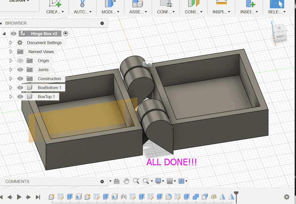
In the second week, I designed a box in which I planned to integrate my boards and the electronic components for my irrigation system.
Pseudocode (February 12th)
Here is a simple pseudocode I made and revised with the assistance of ChatGPT.
            <!-- Start -->
            start
                initialize constants (THRESHOLD_LOW, THRESHOLD_HIGH, MOISTURE_SENSOR_PIN, PUMP_RELAY_PIN)
                initialize variables (moistureLevel)
                setup()
                loop()
                    moistureLevel = readMoistureSensor()
                    if moistureLevel < THRESHOLD_LOW then
                        activatePump()
                    else if moistureLevel > THRESHOLD_HIGH then
                        deactivatePump()
                    end if
                    delay(1000) // Delay for 1 second
                end loop
            end

            // Setup function
            setup()
                initialize serial communication
                set PUMP_RELAY_PIN as output
            end setup

            // Function to read moisture sensor
            readMoistureSensor()
                // Code to read moisture sensor and return the value
                return moistureLevel
            end readMoistureSensor

            // Function to activate the pump
            activatePump()
                digitalWrite(PUMP_RELAY_PIN, HIGH) // Activate pump
            end activatePump

            // Function to deactivate the pump
            deactivatePump()
                digitalWrite(PUMP_RELAY_PIN, LOW) // Deactivate pump
            end deactivatePump
Week 4
In the 4th week, I tried to do a simulation of my final project on tinkercad.😓
Here is a video of the simulation I tried on tinkercad by referring to this tutorial
Here you can see how the LED and DC motor turns on when the soil moisture reading is low and turns off when the reading increases
Fast Cardboard Prototype (February 22nd)😵
Sir Rico and Sir Anith suggested creating a simple cardboard prototype for our final project last week. We completed the prototype on February 22nd, and it was very helpful. It provided us with valuable insights into our project's functionality and design. Additionally, I had to make some adjustments to my design as certain aspects were not accurately represented physically.
Here is the final cardboard prototype
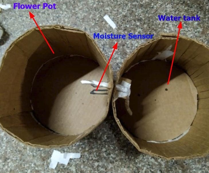
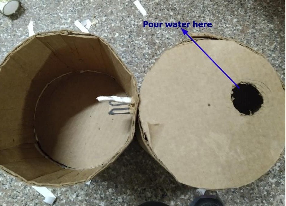
For my final project prototype, I made 2 cylindrical containers which will be around 25 cm long. One will be used for water storage and the other as an attached flower pot. Each cynlinder is divided into 2 halves whereby the section below the flower pot will be used as an excess water collector and the other section under the water storage tank will be used as the circuit storage.
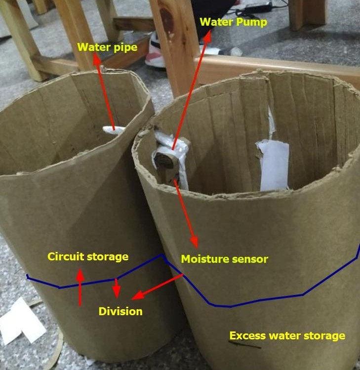
In the above prototype, as all the wires will come through the water storage section and there are also high chances that the moisture sensor will come in contact with water, I am planning to make a different section within the water storage system for the wires to come through and to avoid any contact with water.
Circuit Diagram (March 2nd)
For my final project, I am planning on using the ATtiny1614. Last week, I ran a small simulation on tinkercad for my moisture sensor and I did it using arduino. So, I noted all the pin connections and their compatabilities.
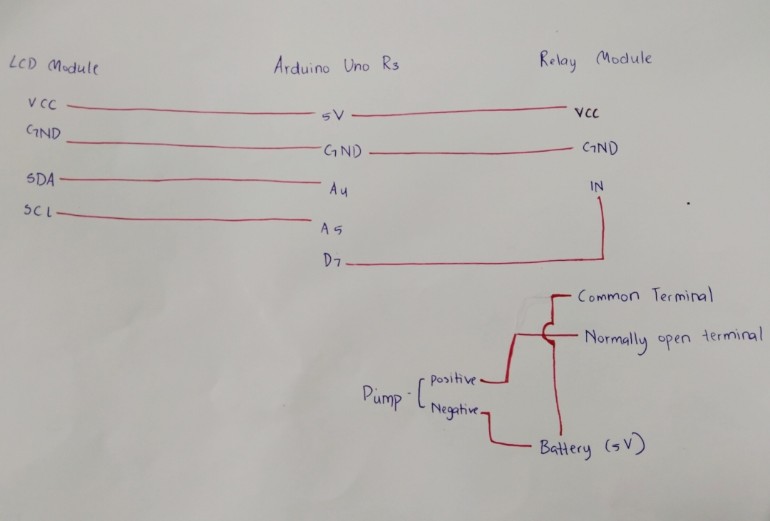
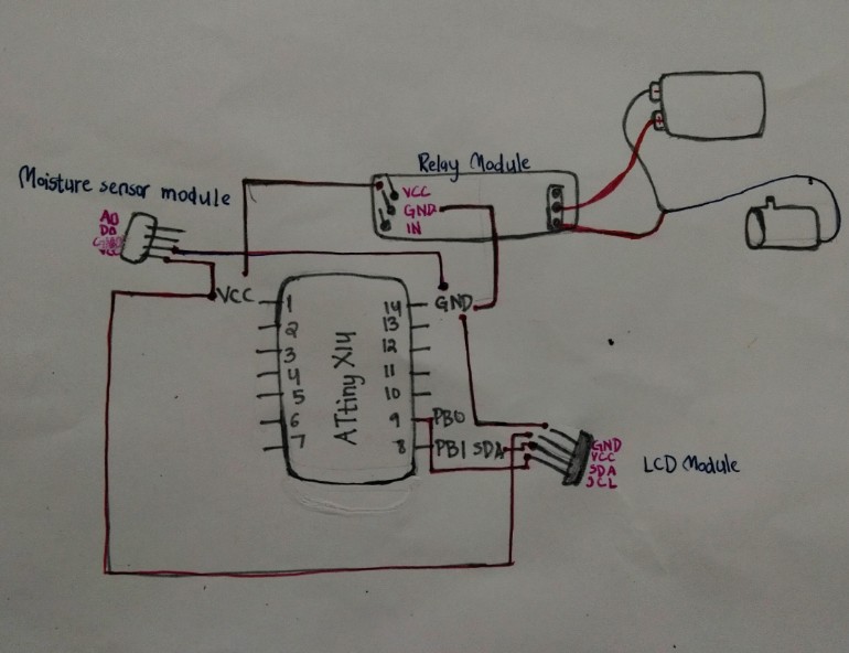
With reference to the above, I made a rough circuit diagram for my project.
Week 6 assignment
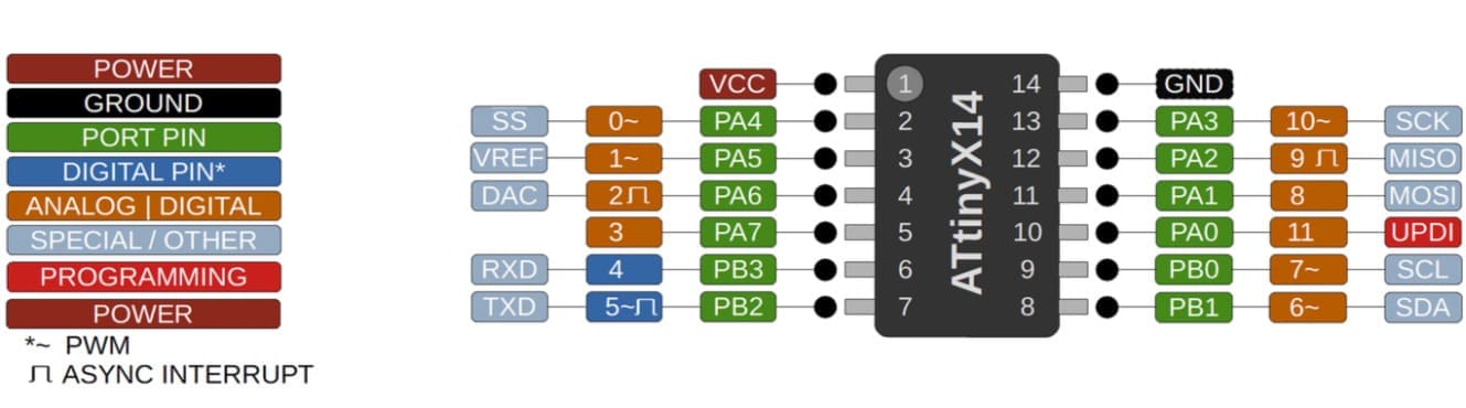
ATtinyX14
So, for this week, I am planning to work on my final project board and I chose ATtiny1614 as my micro-controller.
To program the ATtiny1614 I followed this tutorial and I also referred to Adrian's Documentation
After I made all the connections, I connected my board to the breadboard and the Quentorres to my laptop.
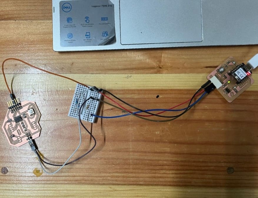
Now, refer to the Quentorres board tutorial to proceed with the remaining steps.
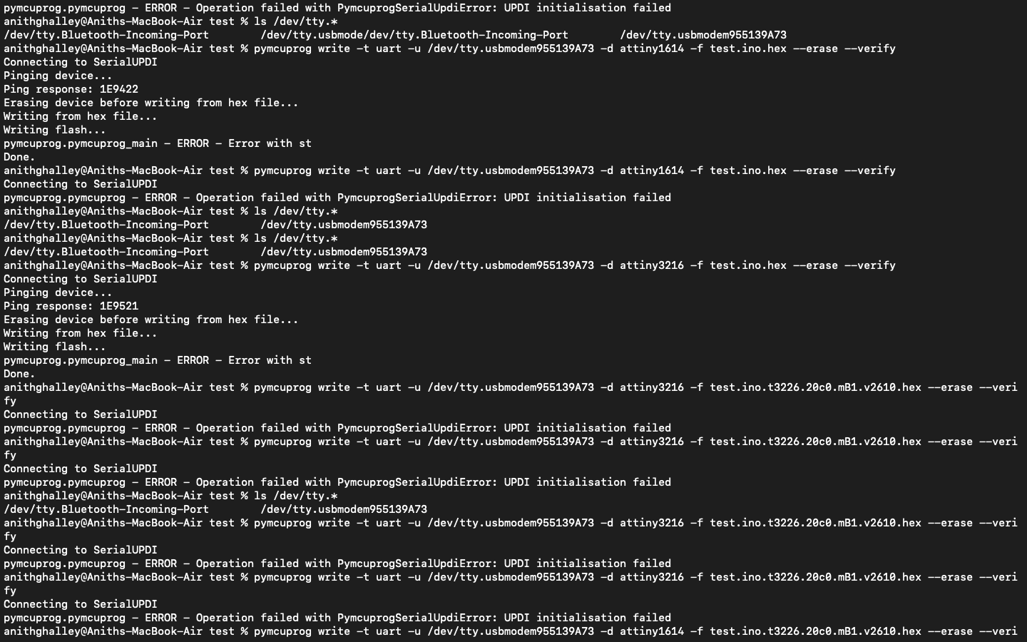
My pymcuprog failed to communicate with the ATtiny so I followed the guide given separately named solution.
After following the steps and running this code, there were some issues uploading.
We ran the code several times but it still showed error.😞
Week 8
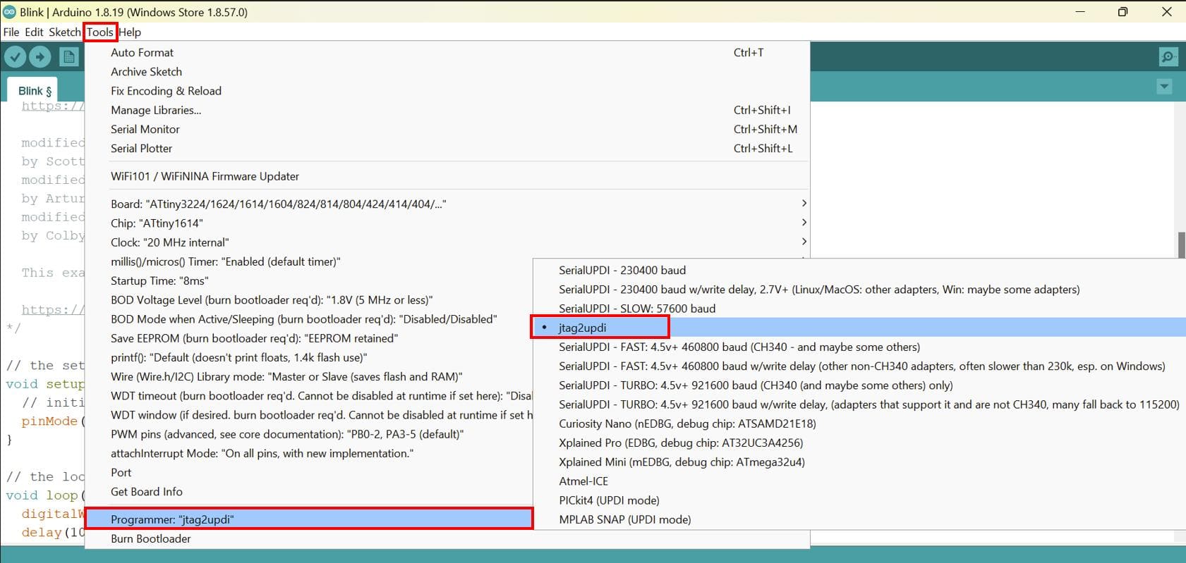
So, for this week as well, I am planning to program the ATtiny1614 but this time, with the jtagUPDI programmer.
To program the ATtiny1614 I followed this tutorial and I also referred to Adrian's Documentation
I am programming my board with Arduino, so I have to select the `jtag2_updi option` as the programmer
Lastly, I uploaded the blink program after setting the pin number to 2 and the LED blinked!!!😀
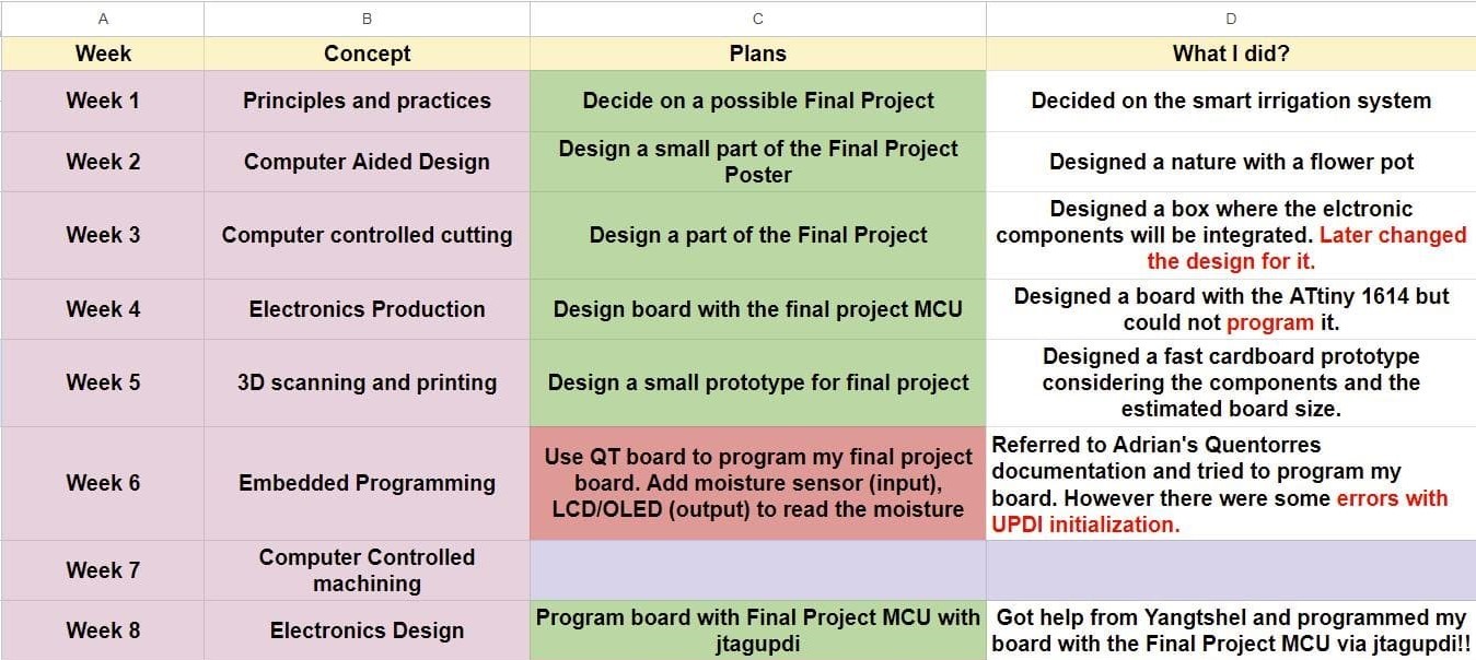
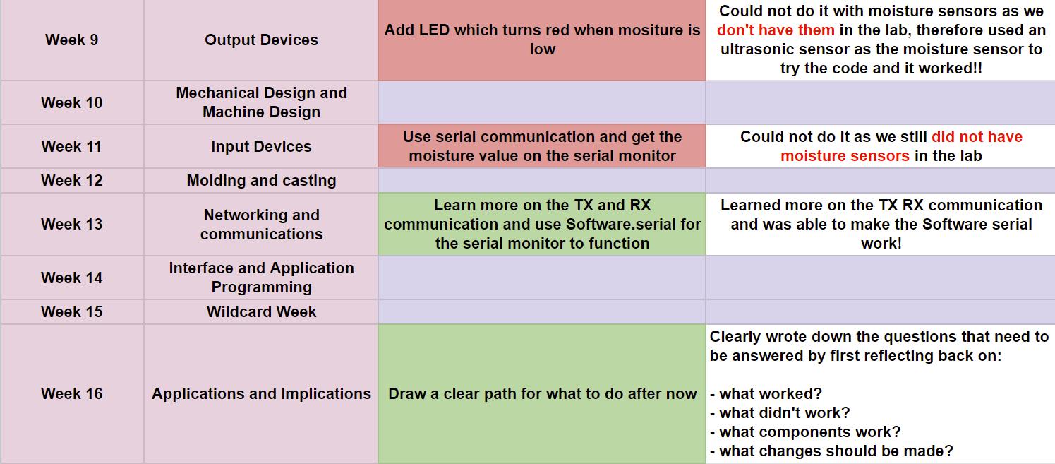
Mid-Term Review (April 3rd)
For the Mid-Term review, on my final project site I listed the tasks completed and made a schedule for the tasks to be completed in the rest of the weeks.
Final Project Board Draft!! (April 5th)
For my final project board, I also needed a motor driver to control my dc water pump which needs 3V-5V power supply. So, I referred to Adrian's Documentation on Adriano where he used the Allegro A4953 to control a DC pump.
Final Project Board 2nd Draft (May 1st)
Again reviewed my final project board and this time I added a connector for the adapter that I will be using. I also added a pin connector for the DC water pump.
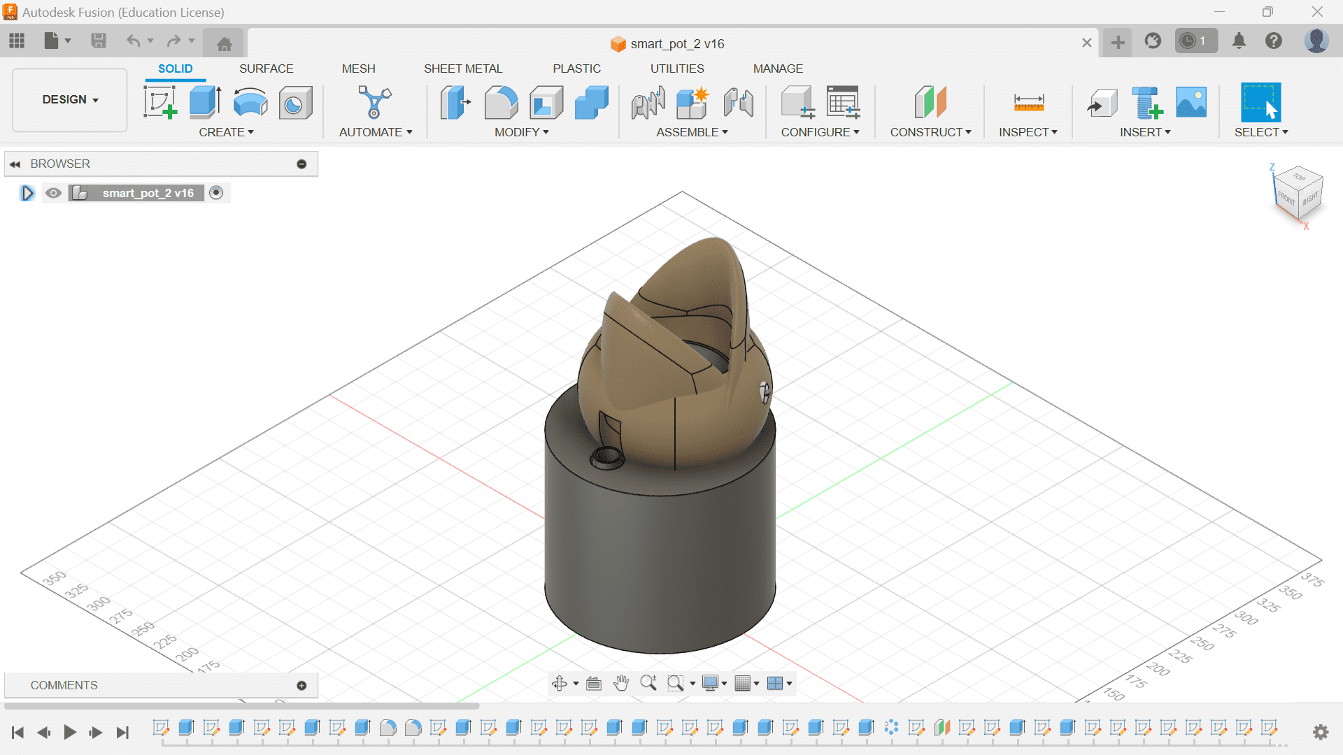
Pot Design (Fusion 360)
For the pot design first I referred to Mr. Pablo Pastor's and designed a similar pot. Now, I want to modify this pot with my own creativity!!😌
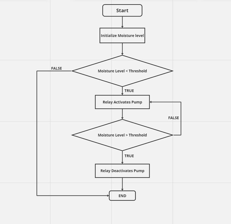
Flowchart (May 1st)
Here is a simple flowchat that I made Micro site for making flowcharts.
Personalized Design (May 10)
Hey there after 10 days!! So today, I am planning on modifying my enclosure and my idea is to integrate a shark mouth to the flower pot.
I got this idea from google, I call it shark pot🐠

I had some trouble making the shark but I managed it using the form tool in Fusion 360.
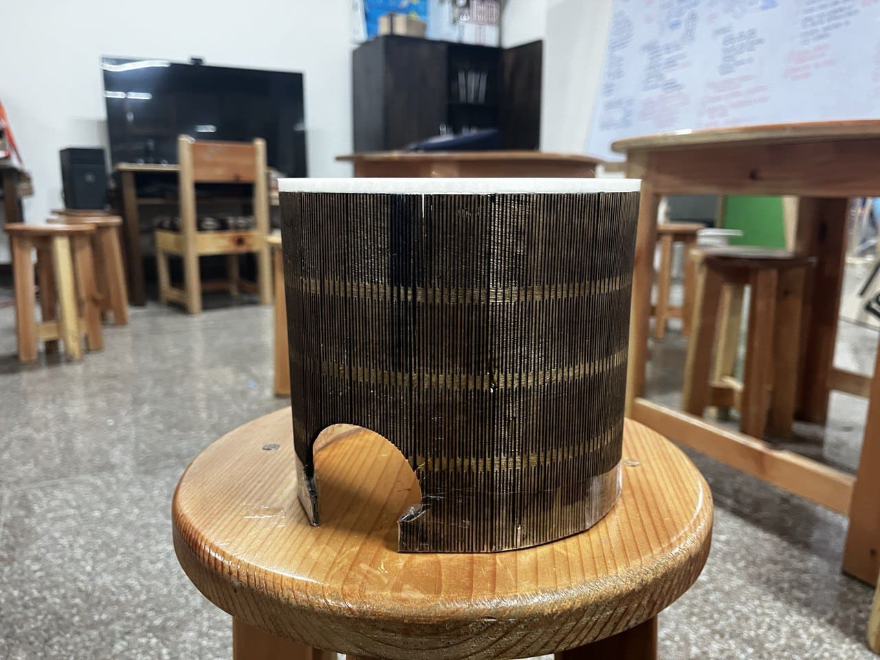
Here comes my first draft enclosure!!😍
I will be going for a nature retreat which last a week, a program held in our school which is very important. So, before going I 3D printed my first draft!! Thank you Damzang for helping me print them!😘
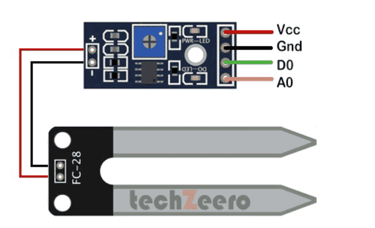
Moisture sensor testing (May 18-Back From Retreat⛺️ )
I finally got the moisture sensor from Amazon yesterday and today I tried to program the sensor with arduino board.
Here is the pinout of the moisture sensor.
I first tried the moisture reading with the Arduino Uno board. I found this code from a YouTube video
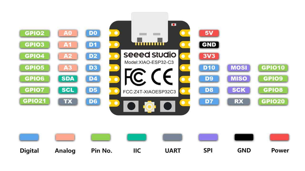
Welcome to the Xiao World! (May 19)
Today, I decided to switch my MCU for my final project from ATtiny1614 to XIAO-ESP-C3 after hearing a lots of compliments and recommendations for it from many fab members especially Sir Rico and he is coming to Bhutan today!!
Here I am now and here is the pinout of the ESP board.
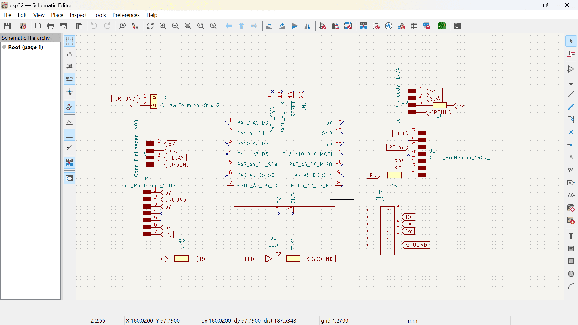
This is my schematic for the board.
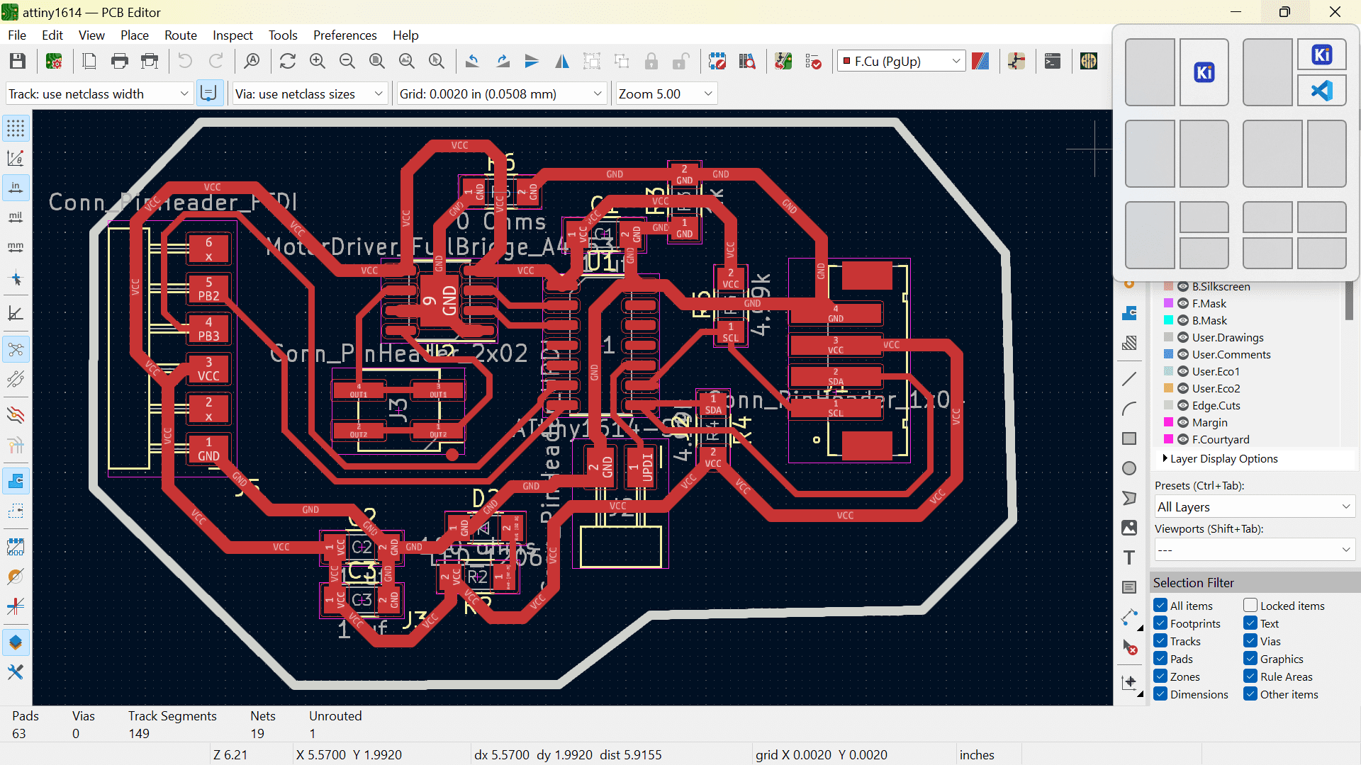
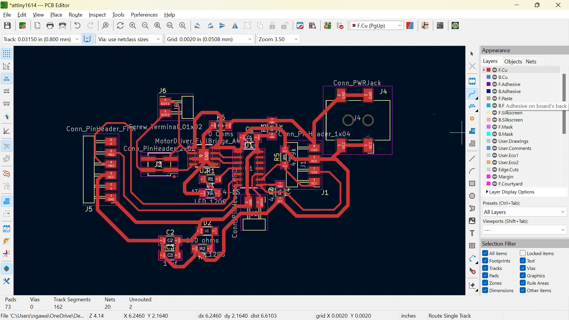
Here is the PCB of the board.
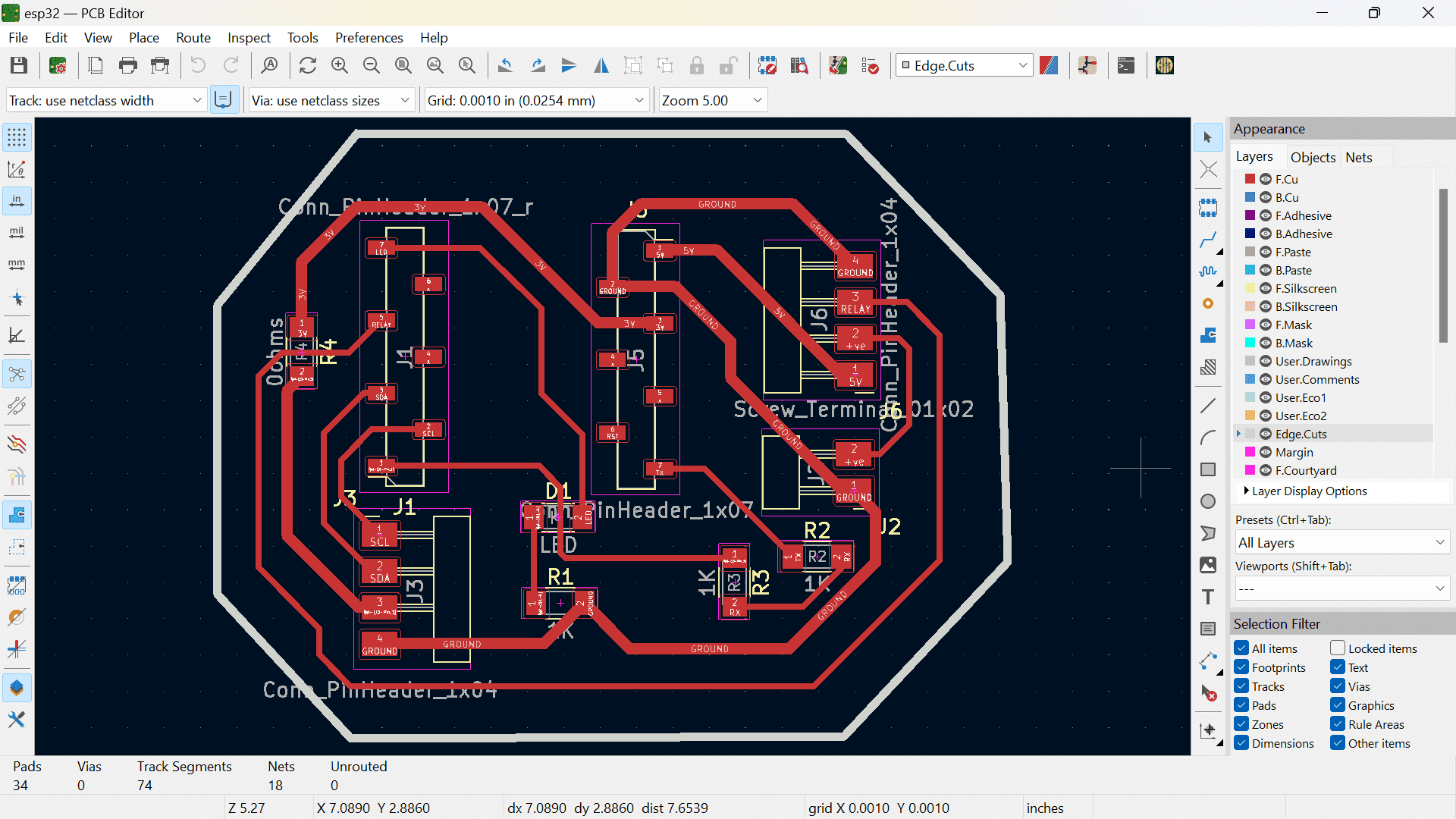
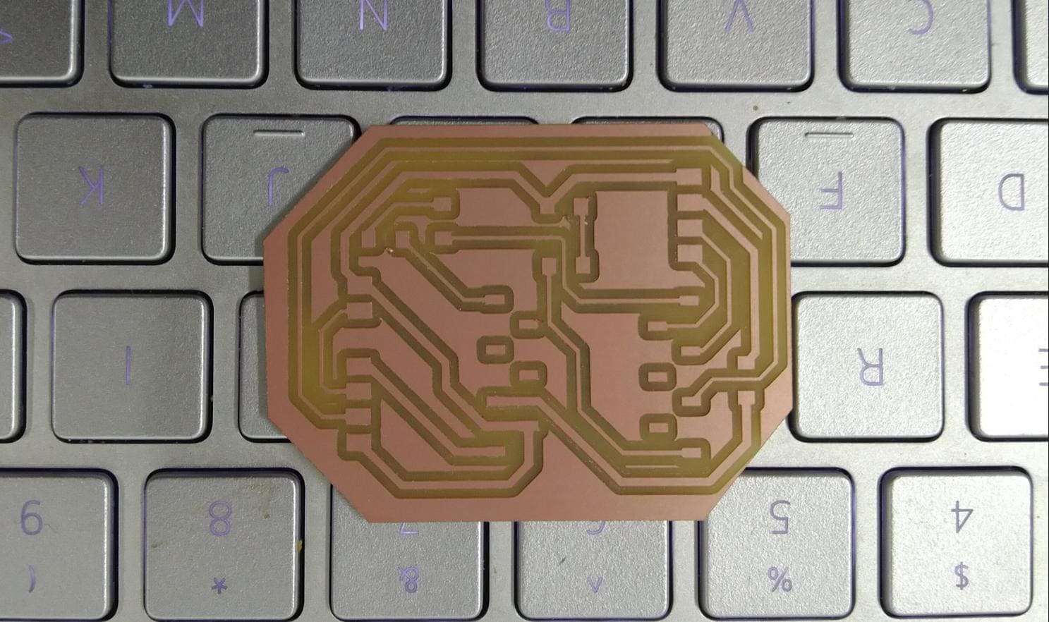
And here is my board!
ESP Programming!! (May 20)
It was my first time programming with XIAO-ESP-C3 so I got a little help from my friends, Thinley and Yangtshel! I got my LED to blink which is a good start but after some analysations, I noticed some issues with my board.
First off, I connected my moisture sensor input pin with a digital pin on the XIAO board. Then, I had some weird connections between my TX and RX pins which left me confused as well.😕
Lastly, I missed one VCC pin connection for the water pump.
As we have Sir Rico to help us with our final project for the next 5 days or so, we are planning to have our Final Project Sprint!!🏃
For today, I first tried to manually solve my board issues with soldering.
Then after having all my connections ready for the programming, I ran the following code generated from chatGPT.
#define moisturePin 5 // Define the analog pin for the soil moisture sensor (use A0 for analog read)
#define relayPin 4 // Define the relay pin

int moistureThreshold = 500; // Threshold value to determine wet or dry soil
int soilMoistureValue = 0; // Variable to store the analog value

void setup() {

  // Initialize serial communication at 9600 bits per second
  Serial.begin(9600);

  pinMode(moisturePin, INPUT); // Set moisture sensor pin as INPUT
  pinMode(relayPin, OUTPUT); // Set relay pin as OUTPUT

  // Initialize the relay to be off
  digitalWrite(relayPin, HIGH);
}

void loop() {
  // Read the analog value from the soil moisture sensor
  soilMoistureValue = analogRead(moisturePin);

  // Determine if the soil is wet or dry and control relay accordingly
  if (soilMoistureValue <= moistureThreshold) {
    Serial.println("Wet");
    digitalWrite(relayPin, LOW); // Turn on relay (and water pump) when soil is wet
  } else {
    Serial.println("Dry");
    digitalWrite(relayPin, HIGH); // Turn off relay (and water pump) when soil is dry
  }

  // Print the analog value for debugging purposes
  Serial.print("Analog Value: ");
  Serial.println(soilMoistureValue);

  // Add a delay for readability
  delay(1000); // Delay in milliseconds (1000 ms = 1 second)
}
The code uploaded after a few trials but the serial monitor was not working so I did some debugging but could not do it. So, I got help from chatGPT to help me figure out the error and a code that it provided.
This one worked but the moisture reading was very inconsistent and inaccurate so more debugging for tomorrow!!
I am replacing my current moisture sensor with a capacitive moisture sensor as it is more durable and efficient. The capacitive sensor doesn't have a DO pin but that's not a problem because I don't need it.😏
Redesign (May 21)
Sir Rico suggested that we do our enclosure design today so here it is!
🤔 Hmm...So I have to redesign my enclosure as there are some issues and I think it is also a bit wiggly.
These are the issues with my old design.
- The body from where water is filled holds the electronic components so, there are chances that the water might come in contact with the electronics.
- The electronic components needs a larger area to fit in for proper integration.
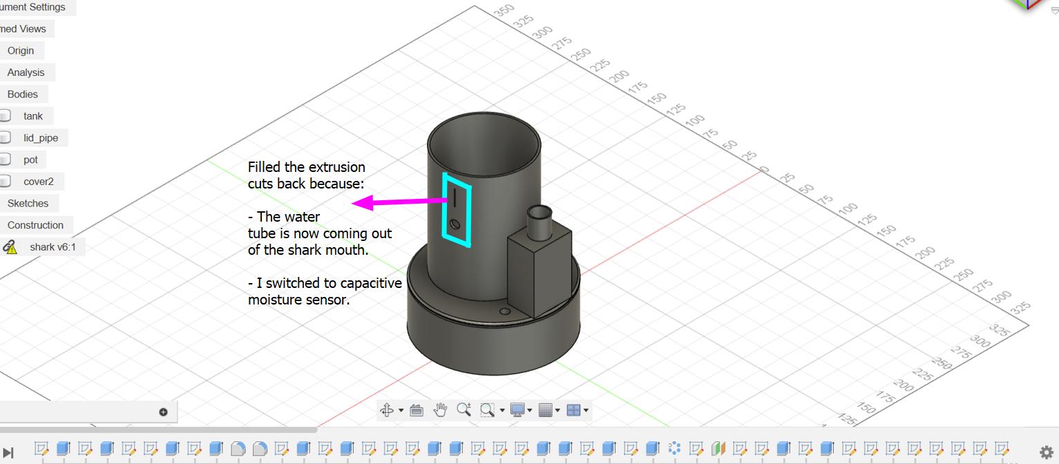
- I switched to capacitive moisture sensor as it is more durable and works more efficiently. So, I have to redesign the slot for it.
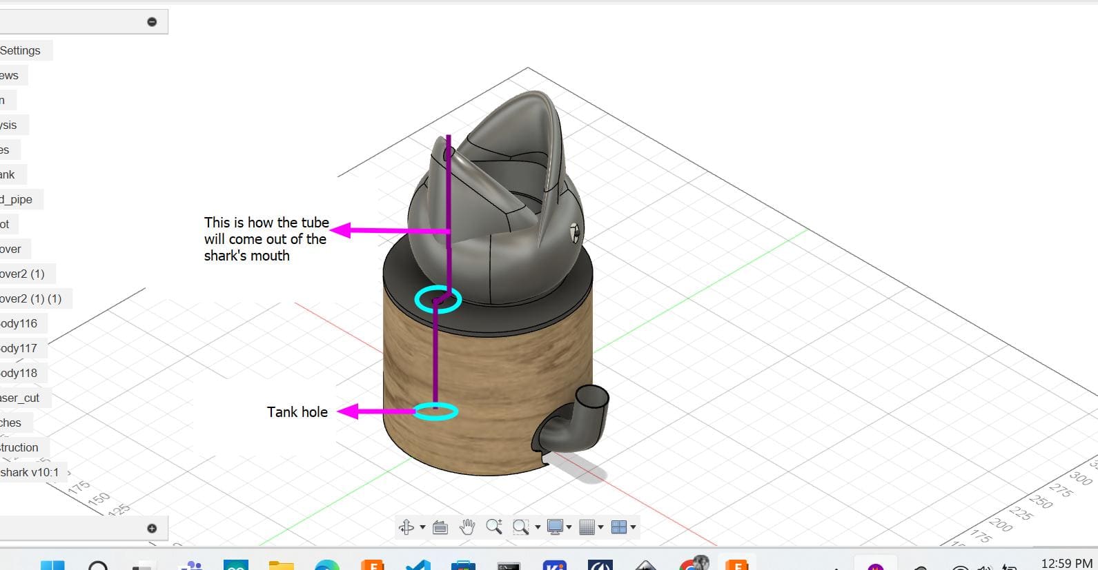
- The water tube was designed below the moisture sensor which was a stupid idea so I designed it in a way that it comes out of the shark's mouth.
These are some notes from Sir Rico and it really guided me with the designing!! 😊
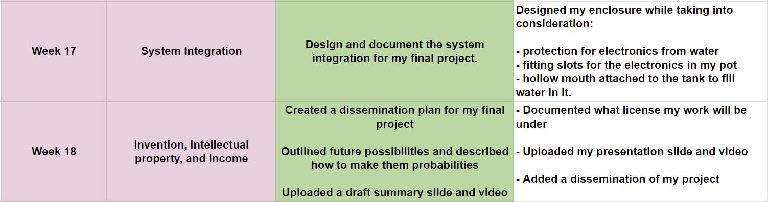
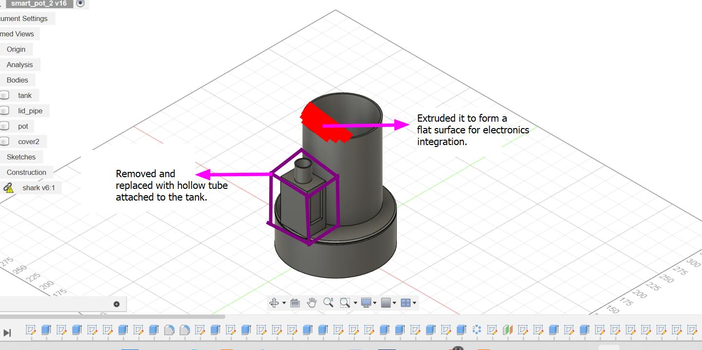
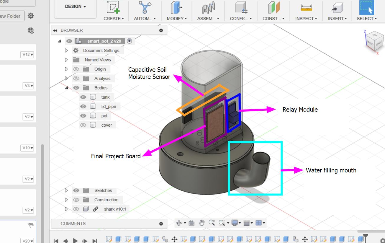
Here are the changes I made to my enclosure:
- Made one side of my pot flat to integrate my boards and relay module.
- Attached a hollow mouth to the tank to fill water in it.
- Created a hollow space in one side of the shark's mouth to fit the water tube and dispense the water from there.
Programming with SEED XIAO ESP32-C3 (May 23 and 24)
So, today there was an issue I faced while uploading the moisture sensor code to my MCU. I used a breadboard for this test as to get all the connections right when I design and print my Final Project board.
This is the first code I uploaded to the XIAO board....
#define sensorPin A3
    #define relayPin 4

    void setup() {
      Serial.begin(9600);

      pinMode(sensorPin,INPUT);
      pinMode(relayPin,OUTPUT);
    }

    void loop() {
      int value = analogRead(sensorPin) ;
      Serial.println(value);

      if(value > 2500){
        digitalWrite(relayPin,HIGH);
        Serial.println("Dry");
      } else {
        digitalWrite(relayPin,LOW);
        Serial.println("Wet");
      }
      delay(800);

    }
....and this error showed up.
I asked Sir Rico for help and the code uploaded when we tried it with Analog pin A1 so it should work for other pins as well!
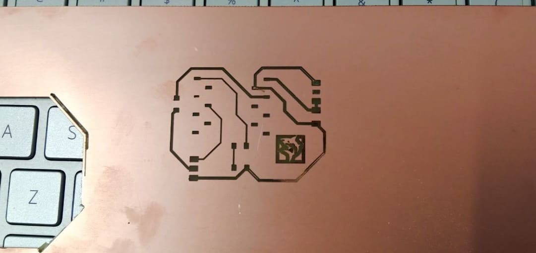
Printing my board again!
2 continuous fails 😠
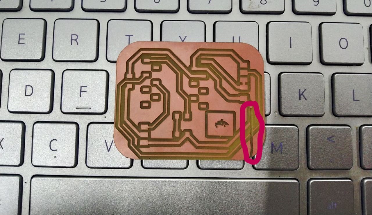
I think I clicked on the invert option twice and tadaa😱
For this one, I think the dimensions of the svg changed while I added a shark icon on my board for the trace mill thus failed to match to my edge cuts😭
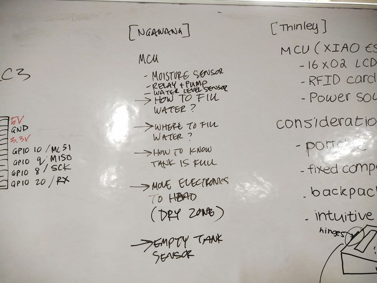
Now, I thought of putting a water level sensor to my Final Project and Sir Rico suggested me to try making my own.
This tutorial showed detailed steps and processes to make a water level sensor with a ribbon cable from old disk or floppy drive but we had none in our lab. So we settled on jumper wires and first tried uploading the code on Arduino Uno. Though the code uploaded, the sensor didn't really sense water.😢
This is the code given in the video description
Here is the sensor:
So...as this one didn't work Sir Rico helped me make one with copper tape.
Here is a list of steps we followed.
- Cut 2 equal stripes of copper.
- Put them in between clear tape but stick a small part out for soldering.
- Then solder a male to male connector to the copper tapes and we're done!
This one worked but I forgot to record itt!!😔
Confusion solved (May 25)
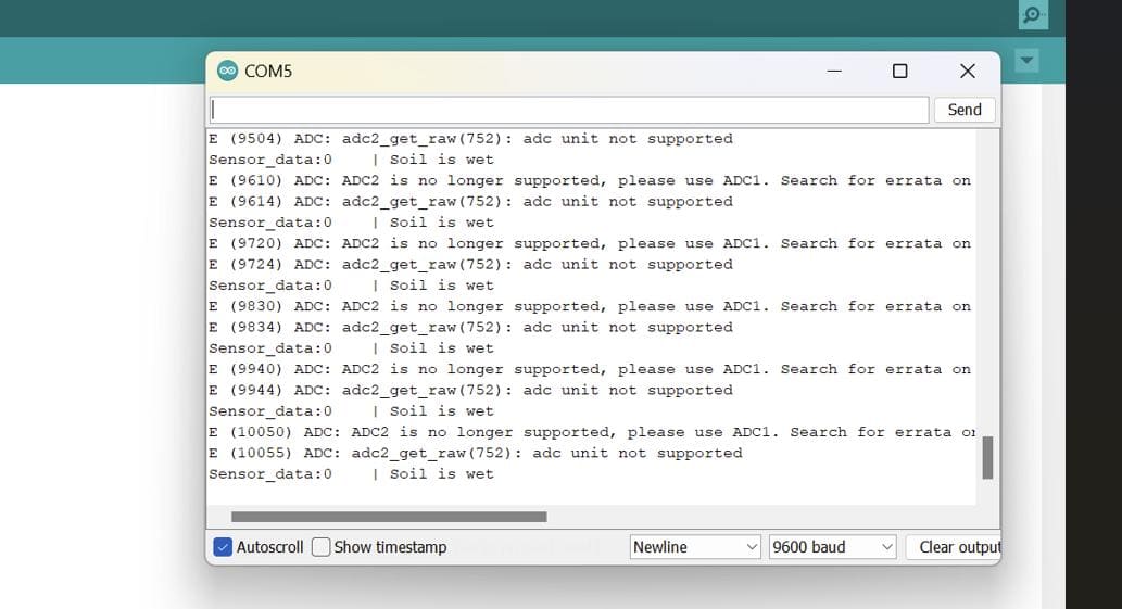
After trying the code back on my final project board where the capacitive moisture sensor is connected to A4, I got back the same error.
Hmm...now I had to research on that and while doing so, I came across this documentation and Eureka!!
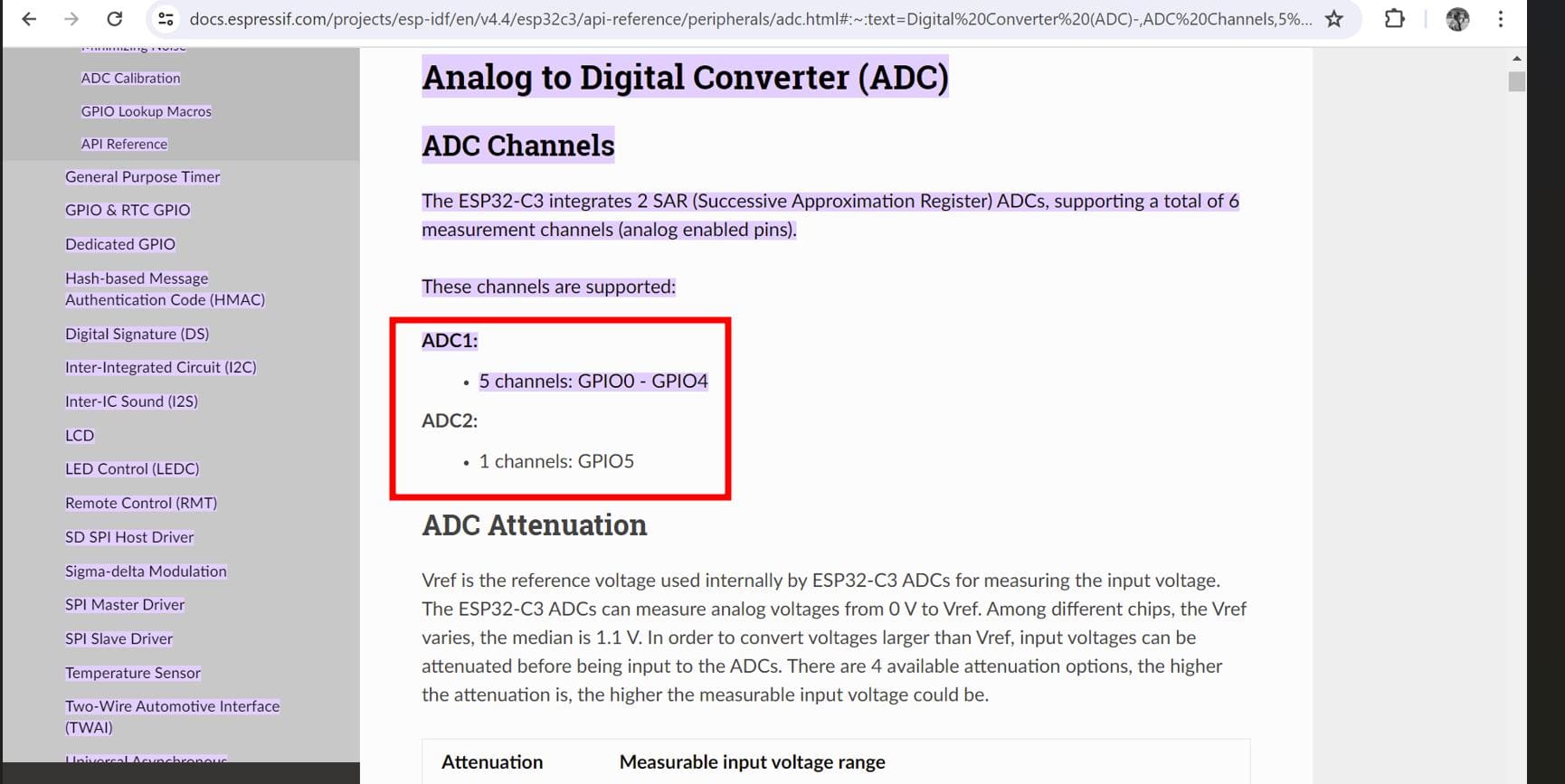
The ADC2 which is GPIO5, A3 was no longer supported and was suggesting me to use the ADC1. So, I have to redesign my board again.
May 26 (Laser Cutting)
So today, I made a design in Fusion 360 for my overall project cover.
Here are the results!!
May 27 (Water level sensor!)
The water level sensor with the copper plate was a fail as the XIAO-ESP-C3 doesn't have built in touch sensors. So, instead of this I am adding a capacitive sensor to my tank. Hope this works well.
June 1st (Welcome to JUNE!!)
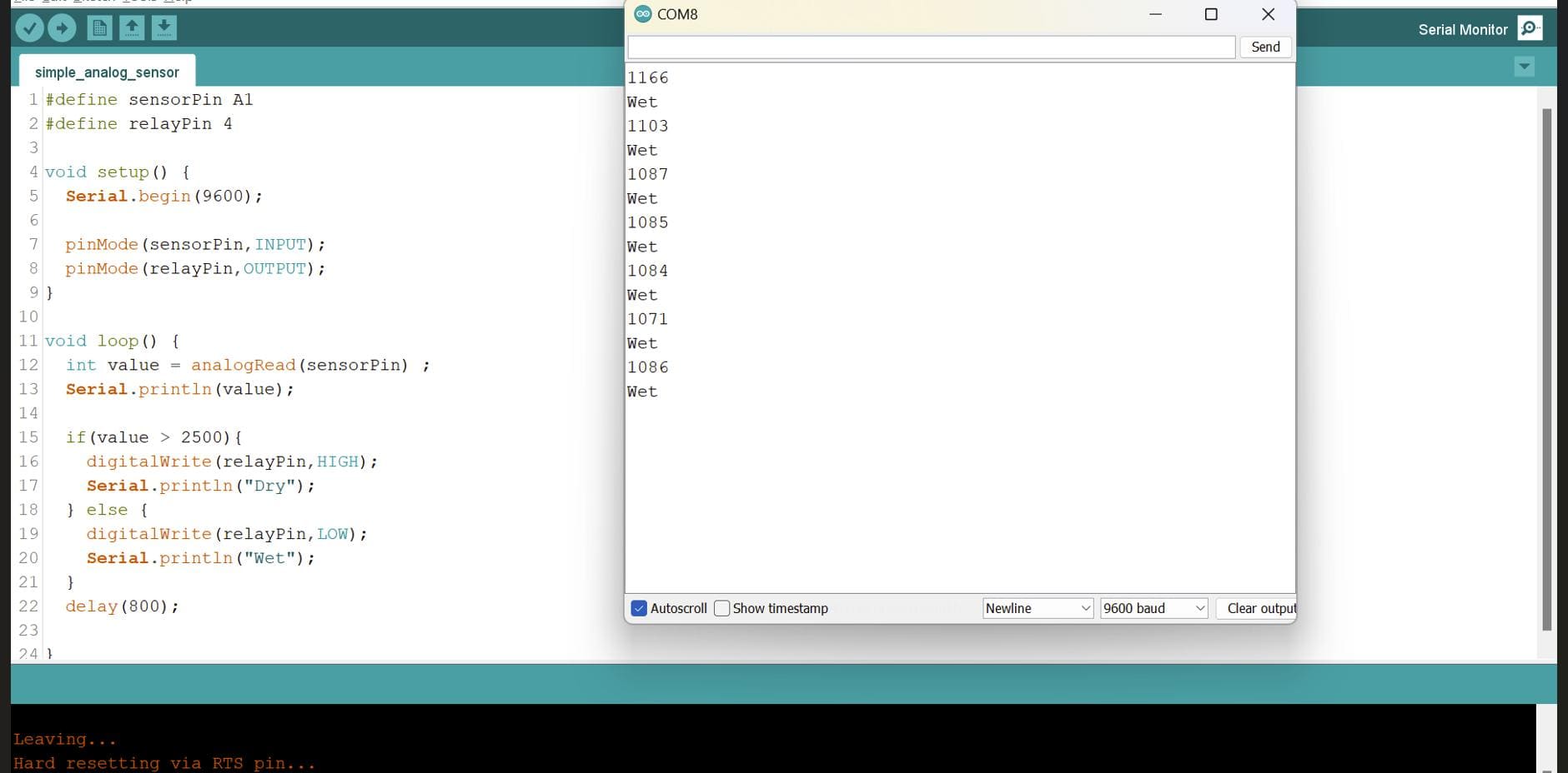
So yesterday, I tried programming my project with my latest board and it works alrightt!!
Here is the code
#define sensorPin A3
#define relayPin 4

void setup() {
    Serial.begin(9600);

    pinMode(sensorPin,INPUT);
    pinMode(relayPin,OUTPUT);
}

void loop() {
    int value = analogRead(sensorPin) ;
    Serial.println(value);

    if(value > 2500){
    digitalWrite(relayPin,HIGH);
    Serial.println("Dry");
    } else {
    digitalWrite(relayPin,LOW);
    Serial.println("Wet");
    }
    delay(800);

}
However, I think I need to redesign my board again because the one that I have right now is a bit fragile. Thus, I switched to through hole soldering!!
June 4th
Today, I planned on making a door which will serve as a slot for my power supply cable.
Here is the design that I made in Fusion 360🤩
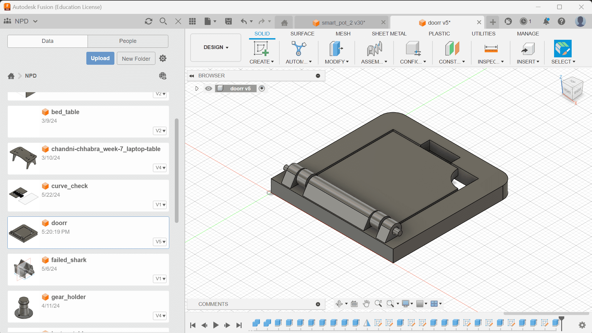
Now, with the addition of the door, I will also have to make a slot in the laser cut cover😴
June 6th
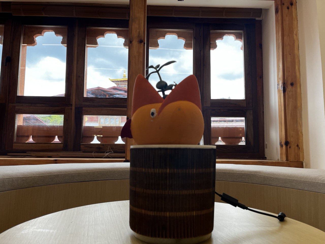
After assembling them, this is how it looks!
Project Progress Tracking and Planning