Week 12. Mechanical Design, Machine Design
Group Assignment
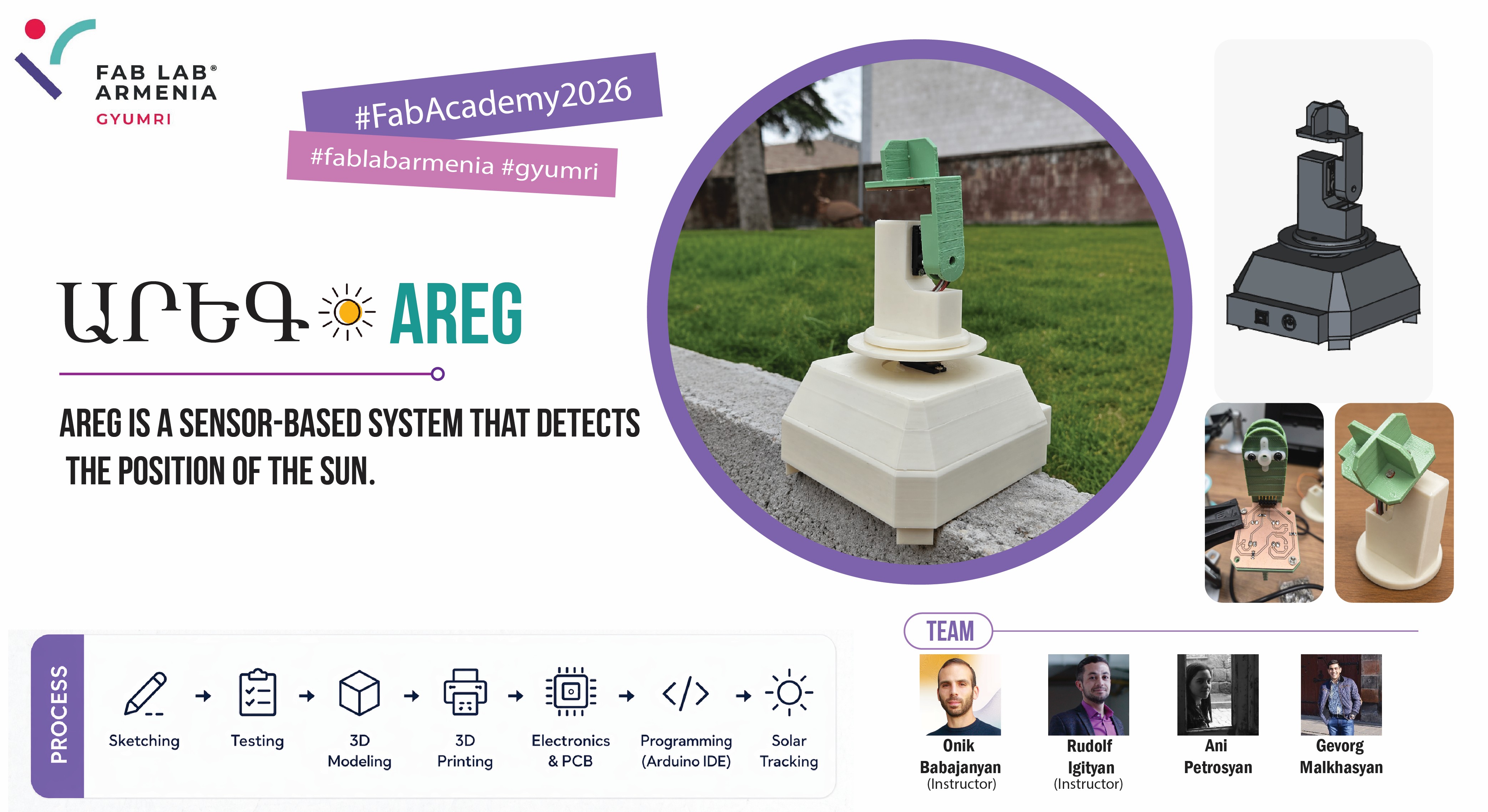
During our Machine Building week, Gevorg and I, upon the suggestion of our instructor Onik Babajanyan, decided to build a solar tracker—a device that follows the movement of the sun and helps determine its position throughout the day.
The study and creation of this device are especially relevant in Armenia, as there are nearly 300 sunny days throughout the year.
A solar tracker is a system composed of mechanical and electronic components that automatically changes its position by following the sun’s movement in the sky. It constantly monitors the sun’s position and accordingly rotates or tilts itself to remain correctly aligned.
We began exploring the different types of solar trackers, which are quite numerous. However, it was not possible to find complete and accurate information about all of them. Nevertheless, we identified five types that are currently among the most widely used and relevant worldwide.
We divided the work into several stages to make the project more organized and efficient. In the initial stage, Gevorg worked on sketching the device design, developing early concepts for the overall appearance and main structural solutions. Two different sketches were created, which allowed us to compare ideas, evaluate their advantages and disadvantages, and select the most suitable and practical option based on functionality, usability, and manufacturability.
After that, Gevorg continued with the more technical part of the design process by developing the PCB (Printed Circuit Board) and schematic design. In this stage, the electronic circuits were defined, the necessary components were selected, and the PCB layout was designed, with special attention given to correct component placement and optimized routing to ensure reliable system operation.
After completing the design phase, we moved on to the mechanical and motion system of the project. Since the solar tracker needed to move along two axes, it was necessary to select appropriate motors and ensure that they could provide the required movement while also handling the structural load. For this purpose, we studied different servo motors, compared their technical specifications, and carried out several tests.
Motor Testing
We needed to ensure both vertical and horizontal rotation of the system, so we considered two different types of servo motors to achieve the required movements.
| Feature | HK-15138 Servo Motor | Corona DS-939MG Servo Motor |
|---|---|---|
| Image | 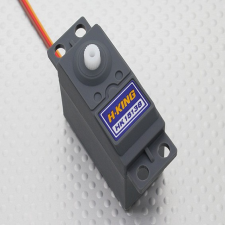 |
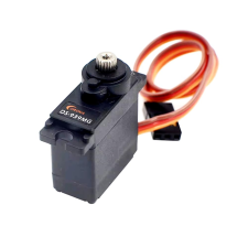 |
| Motor Type | Standard analog servo | Digital metal gear servo |
| Operating Voltage | 4.8V – 6V | 4.8V – 6V |
| Torque | ~4.3 kg.cm | ~2.5–2.7 kg.cm |
| Current | ~0.7–1 A (load dependent) | ~0.2–0.24 A (normal operation) |
| Speed | ~0.17 sec/60° | ~0.13–0.14 sec/60° |
| Gear Type | Plastic gears | Metal gears |
| Weight | ~38 g | ~12.5 g |
| Rotation Angle | ~180° | ~180° |
| Control Signal | PWM | PWM |
One of the main challenges during the project was selecting a servo motor that could provide sufficient torque while still operating within the power limitations of our system. We initially considered using a more powerful motor to improve load handling, especially for supporting the upper moving structure. However, this created an important constraint: higher-torque servo motors require significantly more current, which exceeds the power that can be safely supplied by the Arduino Uno. Using such a motor would have required an additional external power source and more complex power management.
Since our microcontroller was an Arduino Uno, we also had to ensure that the combined current consumption of both motors would not exceed 500 mA. This limitation became the key factor in our decision to choose the Corona DS-939MG servo motor, as it provided a practical balance between mechanical performance and electrical feasibility.
Taking these constraints into account and after studying the technical specifications, we selected the CORONA CS-939MG servo motor as the most suitable option for our project. Although its torque is lower than that of the HK-15138, it offers significantly lower current consumption, allowing the system to operate within the power limitations of the Arduino Uno. In addition, its metal gears provide better durability and reliability under continuous operation and mechanical load, which is important for the moving mechanism of the solar tracking system.
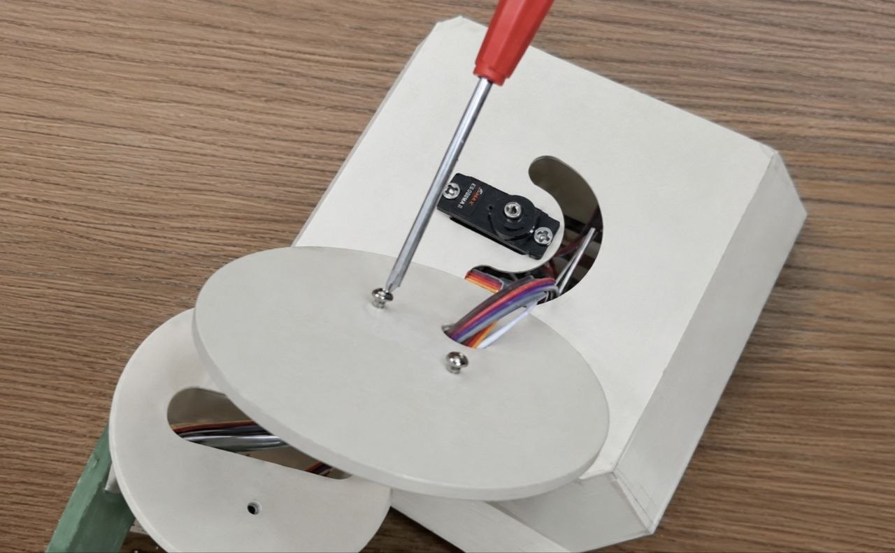
After selecting the servo motor, we performed a series of tests to evaluate its ability to support the weight of the upper part of the system. The motor was tested both with and without load by rotating it from 0° to 180° and back while observing its stability, smoothness of motion, and responsiveness.
For this test, we used the official Arduino example code from the Arduino documentation on servo motors.
#include <Servo.h>

Servo myservo;  // create servo object to control a servo
// twelve servo objects can be created on most boards

int pos = 0;    // variable to store the servo position

void setup() {
  myservo.attach(9);  // attaches the servo on pin 9 to the servo object
}

void loop() {
  for (pos = 0; pos <= 180; pos += 1) { // goes from 0 degrees to 180 degrees
    myservo.write(pos);              // tell servo to go to position in variable 'pos'
    delay(15);                       // waits 15ms for the servo to reach the position
  }
  for (pos = 180; pos >= 0; pos -= 1) { // goes from 180 degrees to 0 degrees
    myservo.write(pos);              // tell servo to go to position in variable 'pos'
    delay(15);                       // waits 15ms for the servo to reach the position
  }
}
This code continuously rotates the servo motor from 0° to 180° and back, allowing us to observe its behavior during repetitive motion.
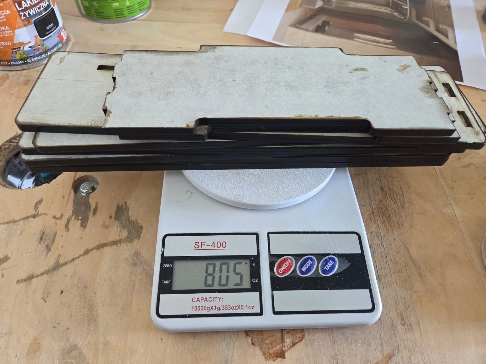
After confirming the basic operation of the motor, we carried out additional load tests to simulate real operating conditions. The total weight of the upper structure was measured to be approximately 805 grams.
Considering that the selected servo motor can support a load of up to approximately 250 grams at a lever length of 10 cm, we evaluated whether it would be sufficient for our structure.
In addition, we investigated another load configuration in which the load was positioned vertically in a hanging state.
The results of these experiments showed that the servo motor was able to operate stably and provide the required motion even under load conditions. These findings formed the basis for the final motor selection and confirmed its suitability for use in our solar tracking system.
My Contribution
In this machine building project, my main contribution was focused on the mechanical design and assembly of the lower part of the solar tracker system.
I was responsible for designing the lower enclosure, integrating the Arduino Uno and servo motor placement, preparing the parts for 3D printing, and assembling the final mechanical structure.
In addition, I participated in the servo motor selection and testing process, evaluated the mechanical limitations of the system, and contributed to the integration and testing of the final assembled machine.
3D Modeling and Printing
After clarifying all of the above, we moved on to the 3D modeling phase of the system. In this stage, we divided the work to make the process more efficient: I was responsible for designing the lower housing, while Gevorg worked on modeling the upper part of the system.
The first servo motor, which is responsible for the horizontal axis rotation, had to be placed together with the Arduino Uno inside the lower compartment. This was due to dimensional limitations and component placement requirements, which led to the design of the lower part being developed based on this structural solution, while also aligning it with our PCB design.
However, there was one important aspect in this process: the dimensions and hole placements of both my and Gevorg’s designed parts were interconnected with a single key structural element of the housing. Therefore, the accuracy and proper alignment of the entire system depended on the correct design of this component.
To begin the modeling work, we first downloaded the 3D models of the main components used in the system, specifically the Arduino Uno board and the servo motor. This step was important because it allowed us to accurately calculate the internal dimensions of the enclosure and the placement of the components from the early stages of the design.
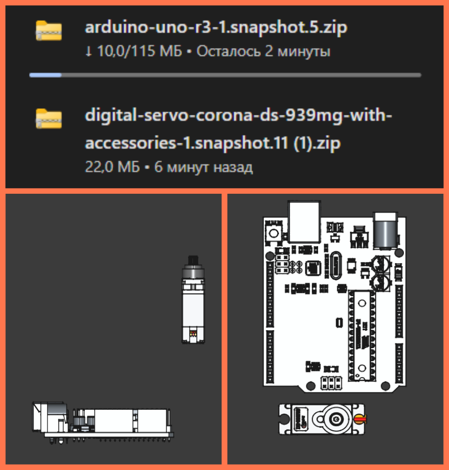
The images show the process of integrating the downloaded 3D models into the design environment. The servo motor and Arduino Uno models were placed in the working area of the project to examine their relative positions, mounting possibilities, and the required space inside the lower enclosure.
This approach helped to prevent dimensional mismatches in advance, ensure the correct positioning of mounting holes, and design a more compact and stable structure before moving on to the 3D printing stage.
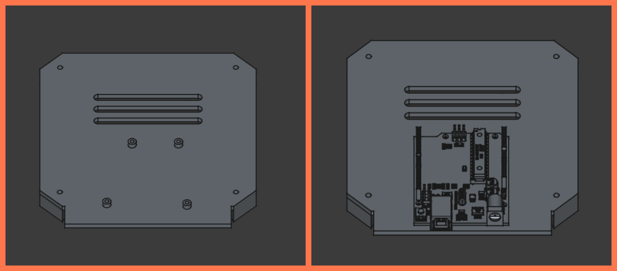
The image shows the overall structure of the project in a transparent (wireframe) view, where the arrangement of the internal components inside the enclosure is clearly visible. This view makes it possible to see how the Arduino Uno board and the servo motor are positioned in the lower part of the enclosure, as well as to evaluate the spacing between them and their mounting positions.
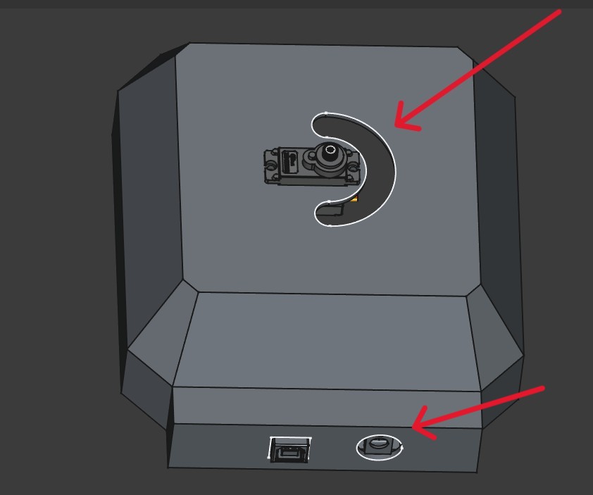
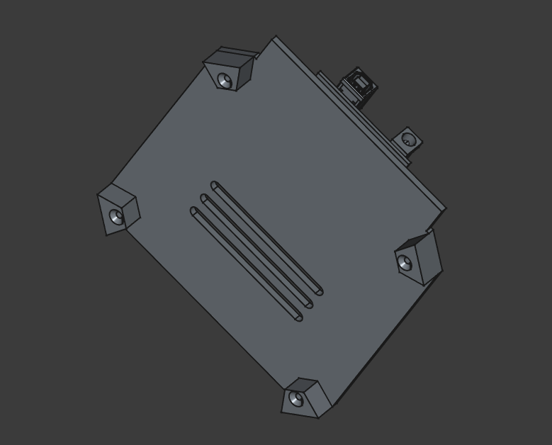
This image shows the external appearance of the model with the enclosure fully closed. On the top section, the opening for the servo motor is visible, and next to it there is a slot-shaped hole specifically designed for routing the wires coming from the upper component. This solution allows the wires to be guided into the enclosure in an organized manner, avoiding pressure or damage, while also maintaining a clean and neat design.
The openings on the front side are intended for the placement of connection ports and control elements, ensuring convenient use of the device.
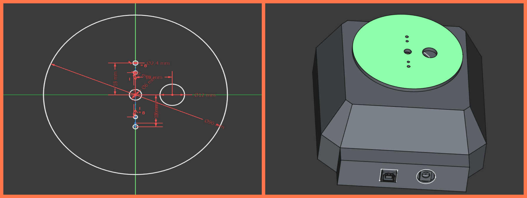
This is the main component that connects the 3D models designed by Gevorg and me. It ensures the proper alignment of the two parts by incorporating the appropriate dimensions and precise placement of the holes.
In the first stage, I designed the enclosure lid by adding support feet to it. These feet are intended to keep the enclosure slightly elevated from the surface it is placed on, preventing direct contact. This ensures air circulation underneath the enclosure and contributes to the overall ventilation of the system.
In addition, I created ventilation holes on the lid, which help cool the internal electronics, particularly the Arduino Uno.
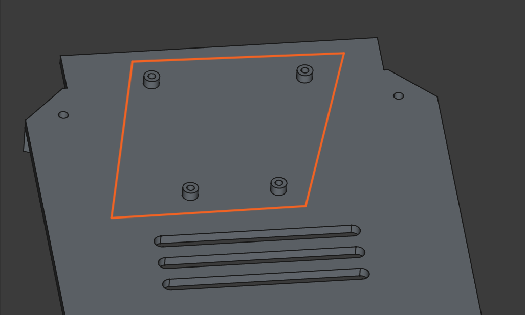
In the second stage, I designed the mounting holes for the Arduino Uno. These holes correspond to the board’s mounting positions and allow it to be securely fixed with screws.
After the modeling work was completed, all parts were exported in STL format and prepared for 3D printing.
I imported the files one by one into the Orca Slicer program. I rotated the main part and placed it on the workbench so that as few supports as possible were required. Then I selected the printer, material type, and adjusted the basic printing parameters.
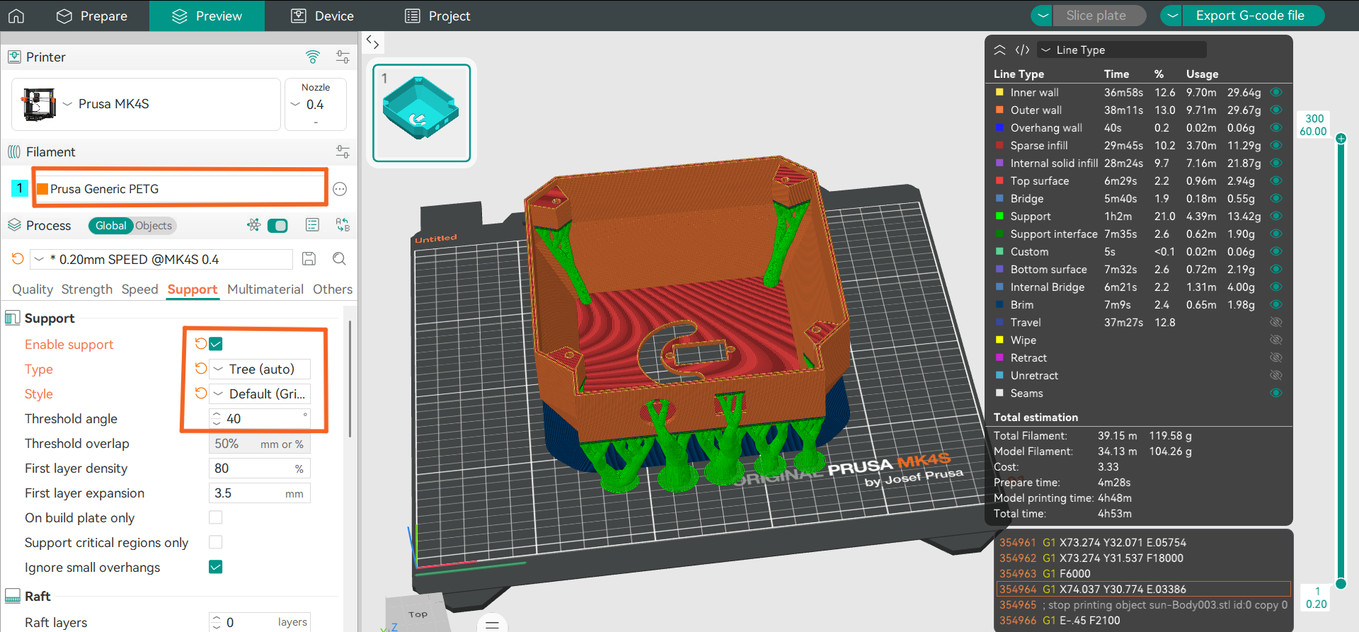
For the supports, I chose the Tree Support option, since in the case of this model it was the most efficient solution. This type of supports uses less material, reduces printing time, and at the same time provides reliable support for hanging parts during printing. In addition, they are easier to remove after printing and leave fewer marks on the surface of the model.
I used the same approach for the remaining two parts. The cover part had protruding elements on both sides, which required supports during printing. Therefore, I placed it so that the side that would later be the inner part of the structure was in contact with the workbench with its entire surface.
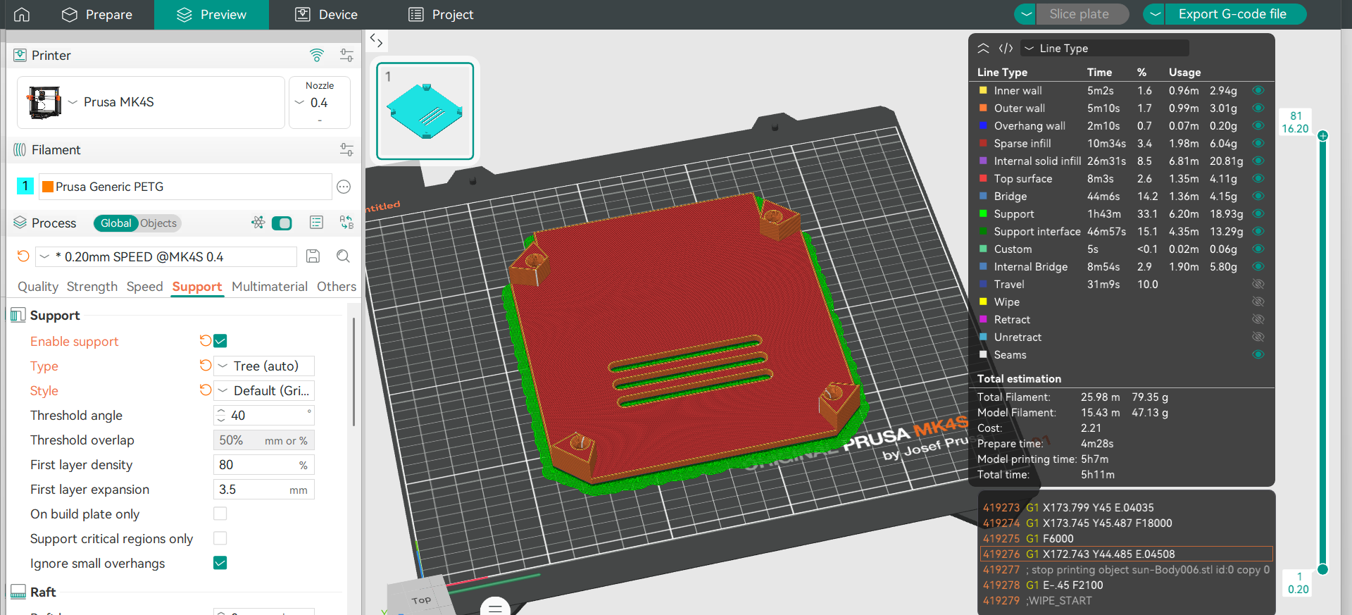
This positioning allowed for better adhesion to the build plate and increased print stability. I then chose the Tree Support option again, as it provided the necessary support for the protruding parts, while using relatively little material.
In the case of the upper round part, there was no need for supports, since its geometry allowed it to be printed without additional supports. I simply positioned the part correctly on the build plate and prepared it for slicing.
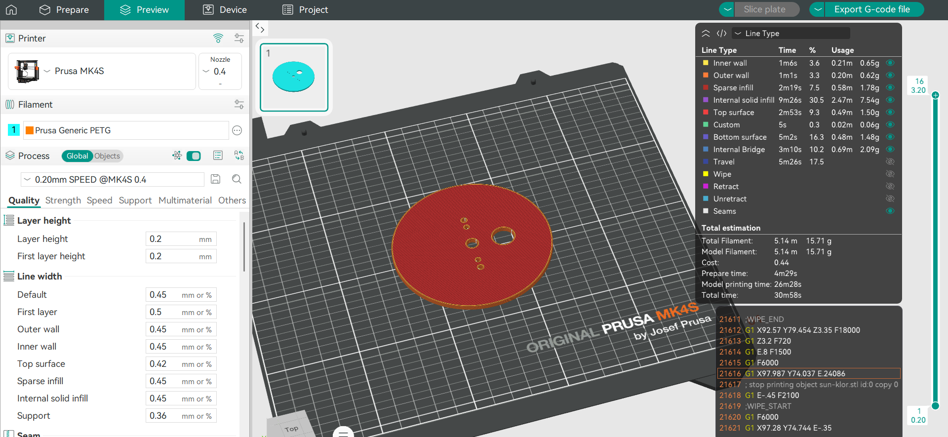
For all three parts, I chose the Generic PETG Vanilla White material. PETG was chosen due to its strength, good layer adhesion, and heat resistance. This material also provides sufficient mechanical stability and is more resistant to external influences, which is important for long-term use of the device.
After a final check of the parameters, a corresponding G-code file was created for each part, and the parts were ready for the 3D printing process.
The design and development of the upper part of the system were carried out by Gevorg, where more detailed information about his work can be found.
System Assembly
After completing the 3D printing process, I began the assembly stage. First, I cleaned the printed parts and removed any remaining support material, ensuring that all surfaces and connection points were ready for assembly. Next, I installed the servo motor into the designated section of the enclosure and secured it firmly to ensure stability during operation.
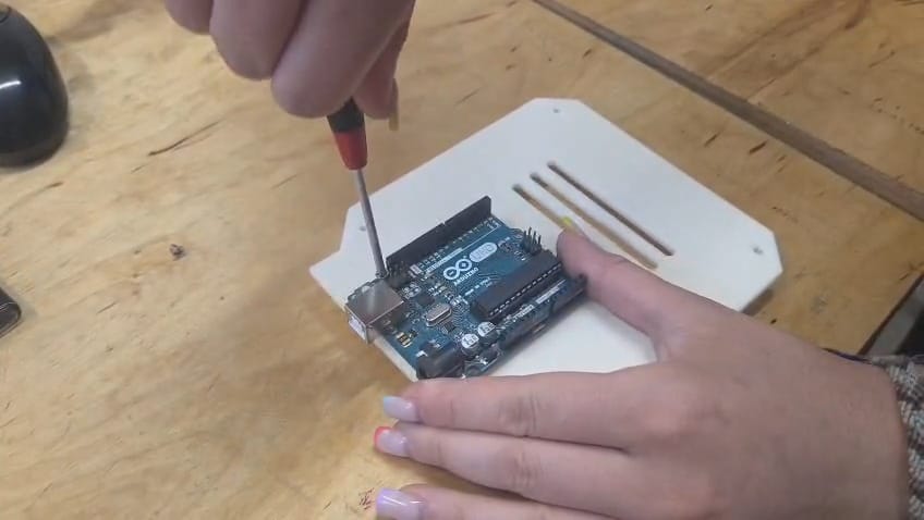
After that, I mounted the Arduino Uno onto the lower cover of the enclosure and fixed it in place using screws.
I then completed all the necessary wiring by connecting the servo motor to the Arduino Uno and verified that all electrical connections were correct.
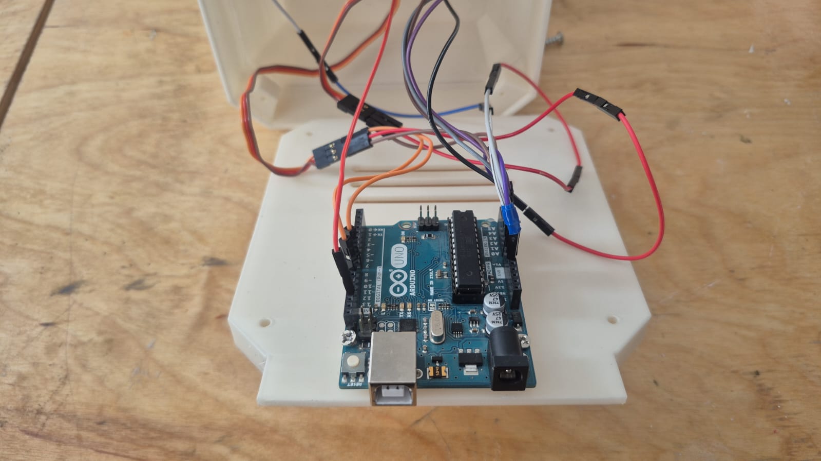
Once the wiring was finished, I closed the bottom section of the enclosure.
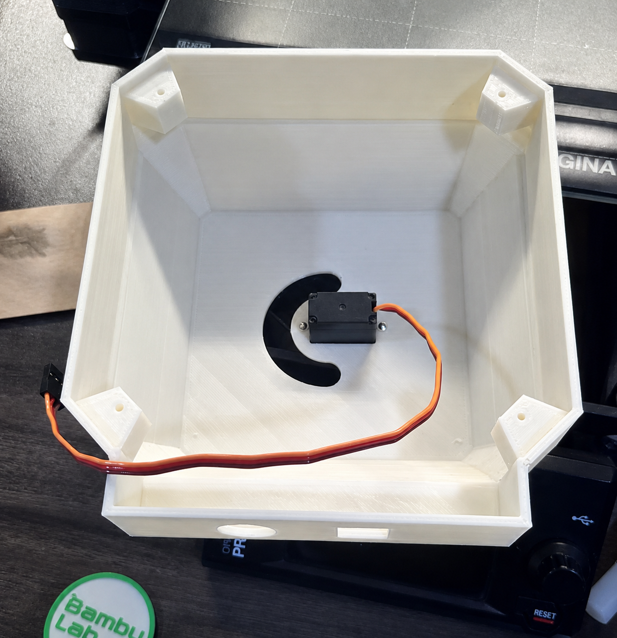
Finally, I mounted the 3D-printed circular component onto the servo motor shaft and secured it in place, allowing the servo motor’s rotational movement to be transferred to the mechanical part.
The final assembled version of the system is shown below.
Coding
After assembling the system, we moved on to the programming stage. The programming was carried out using the Arduino IDE environment. First, we defined the inputs of the four photoresistors and read their values from the Arduino’s analog pins. Using the Serial Monitor, we verified that all sensors were functioning correctly and responding to changes in light intensity.
Next, we determined which pairs of sensors would be used to control the horizontal and vertical axes. Based on the collected data, we developed an algorithm that compares the photoresistor readings and determines the movement direction of the servo motors. If one sensor receives more light than the other, the corresponding servo motor rotates in small steps toward that direction.
In the next step, we added movement limits to prevent the servo motors from exceeding their allowed range of motion. In addition, we applied a threshold value, allowing the system to ignore small differences and avoid constant back-and-forth oscillation.
In the final version, we created a general function that applies the same logic to both the horizontal and vertical axes. As a result, the system is able to automatically detect the brightest direction and move toward it.
During system testing, we evaluated the sensor response under different lighting conditions and adjusted the threshold value to ensure more stable operation. As a result, the device can automatically track the direction of the light source and maintain stable performance under varying conditions.
The complete description of the programming process and the final code are available at the following link․
Conclusion
From this work, we understood that the performance of a solar tracking system depends not only on the control algorithm, but also on the precision of the mechanical structure and the correct selection of actuators.
It became clear that even small changes in load can affect the stability of a servo motor, making proper motor selection a critical factor for the overall system performance.
We also learned that a simple sensor-based comparison algorithm can effectively track the light direction, but it requires additional logic to prevent oscillations and unstable behavior.
Finally, the experiments showed that stable real-world operation is only possible when mechanics, electronics, and software are properly integrated as a single system.