Week 11. Networking and Communications
Group assignment
Details of our group work can be found here.
For this group assignment, Gevorg and I sent a message between our two projects using the I2C protocol. Gevorg’s board, which carries an MQ-7 gas sensor and a piezo buzzer, acted as the Main. My board, which drives an LED strip through a MOSFET, acted as the Secondary, addressed at a fixed I2C address.
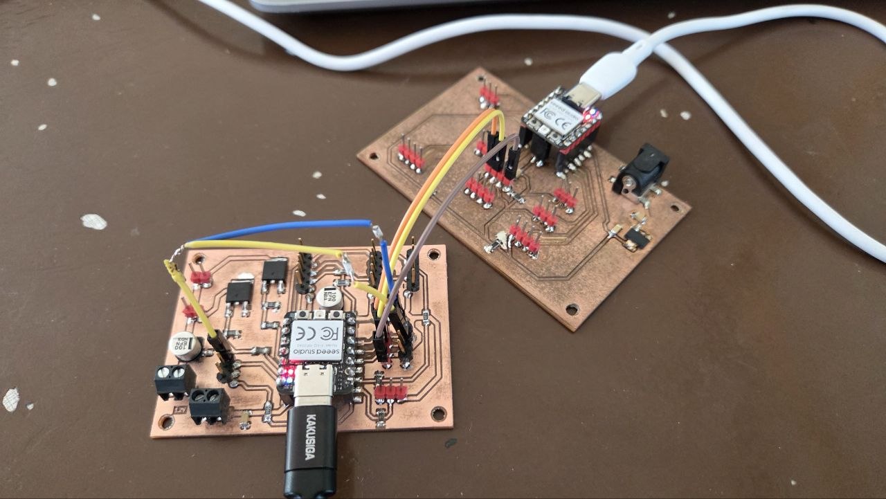
The goal was for Gevorg’s board to read the MQ-7 sensor and decide, based on a threshold, whether the air should be considered safe or dangerous, then send this as a single byte to my board. My board, listening at its fixed address, would receive this byte and switch the LED strip from steady to a fast blink whenever the value indicated danger.
On the XIAO RP2040, SDA and SCL sit on pins D4/D5, but they have to be set explicitly in code with Wire.setSDA() / Wire.setSCL() before Wire.begin() — they aren’t fixed by default the way they are on classic Arduino boards. The bus also needed pull-up resistors, 4.7 kΩ from SDA to 3.3V and from SCL to 3.3V, once for the whole bus; without them nothing on the bus responded at all.
Gevorg’s board (Main):
#include <Wire.h>

#define MQ7_PIN A0
#define SECONDARY_ADDR 0x10
#define THRESHOLD 600

void setup() {
  Wire.setSDA(6);  // D4
  Wire.setSCL(7);  // D5
  Wire.begin();    // join the I2C bus as Main
  Serial.begin(115200);
}

void loop() {
  int gasValue = analogRead(MQ7_PIN);
  Serial.println(gasValue);

  Wire.beginTransmission(SECONDARY_ADDR); // transmit to device #0x10
  Wire.write(gasValue > THRESHOLD ? 0x01 : 0x00);
  Wire.endTransmission();

  delay(200);
}
Let’s explain the code step by step:
- Set SDA and SCL to D4/D5 explicitly, join the I2C bus as Main, and start Serial for debugging.
- In an endless loop, read the MQ-7 sensor on pin A0.
- Compare the reading against a fixed threshold to decide whether the air is safe or dangerous.
- Send the result as a single byte (
0x00or0x01) to my board. - The cycle repeats with a 200 ms delay.
My board (Secondary):
#include <Wire.h>

#define SECONDARY_ADDR 0x10
#define MOSFET_PIN D1

volatile bool alertState = false;

void receiveEvent(int howMany) {
  while (Wire.available()) {
    byte cmd = Wire.read();
    alertState = (cmd == 0x01);
  }
}

void setup() {
  pinMode(MOSFET_PIN, OUTPUT);
  Wire.setSDA(6);  // D4
  Wire.setSCL(7);  // D5
  Wire.begin(SECONDARY_ADDR);   // join the I2C bus with address 0x10
  Wire.onReceive(receiveEvent); // register event
}

void loop() {
  if (alertState) {
    digitalWrite(MOSFET_PIN, HIGH);
    delay(100);
    digitalWrite(MOSFET_PIN, LOW);
    delay(100);
  } else {
    digitalWrite(MOSFET_PIN, LOW);
  }
}
Let’s explain the code step by step:
- Set SDA and SCL to D4/D5, join the I2C bus at the fixed address
0x10, and register the receive handler. - Whenever a byte arrives from Gevorg’s board, store whether it equals
0x01(alert) or not. - In the main loop, if the alert flag is set, blink the MOSFET pin on and off quickly; otherwise keep it low.
Let’s look at the result:
This was my first real use of Wire.onReceive() — reacting to a message as it arrives, instead of just polling a sensor in a loop. It also wasn’t working for a while: the bus stayed completely silent until we added pull-up resistors on SDA and SCL and set the pins explicitly in code, which is when I realized those weren’t optional steps, just things the wiring diagrams I’d seen before had already taken care of for me.
Individual Assignment
For this assignment, I connected three separate Seeed Studio XIAO RP2040 boards using the I²C communication protocol. Instead of building the entire system around a single microcontroller, each board performs a dedicated task and exchanges data with the others through the I²C bus.
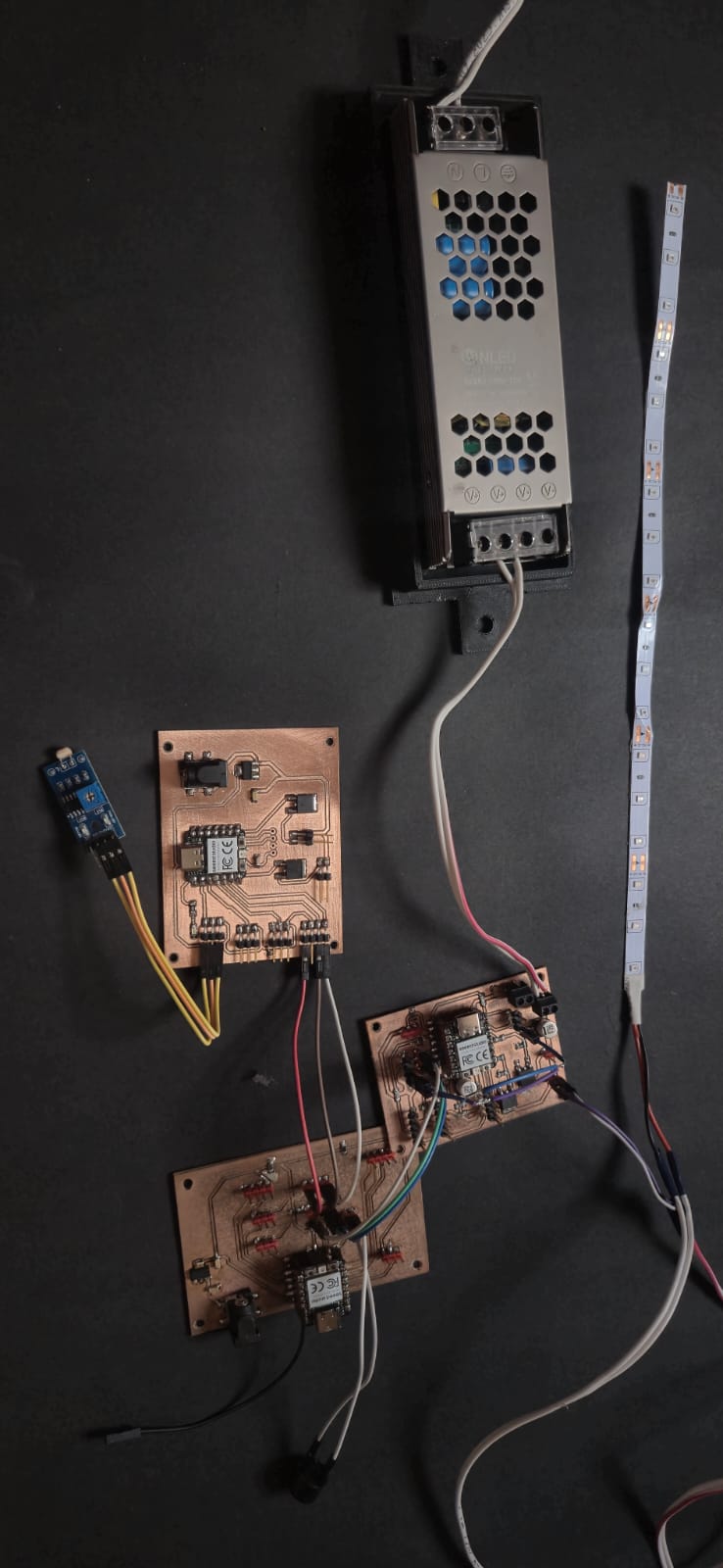
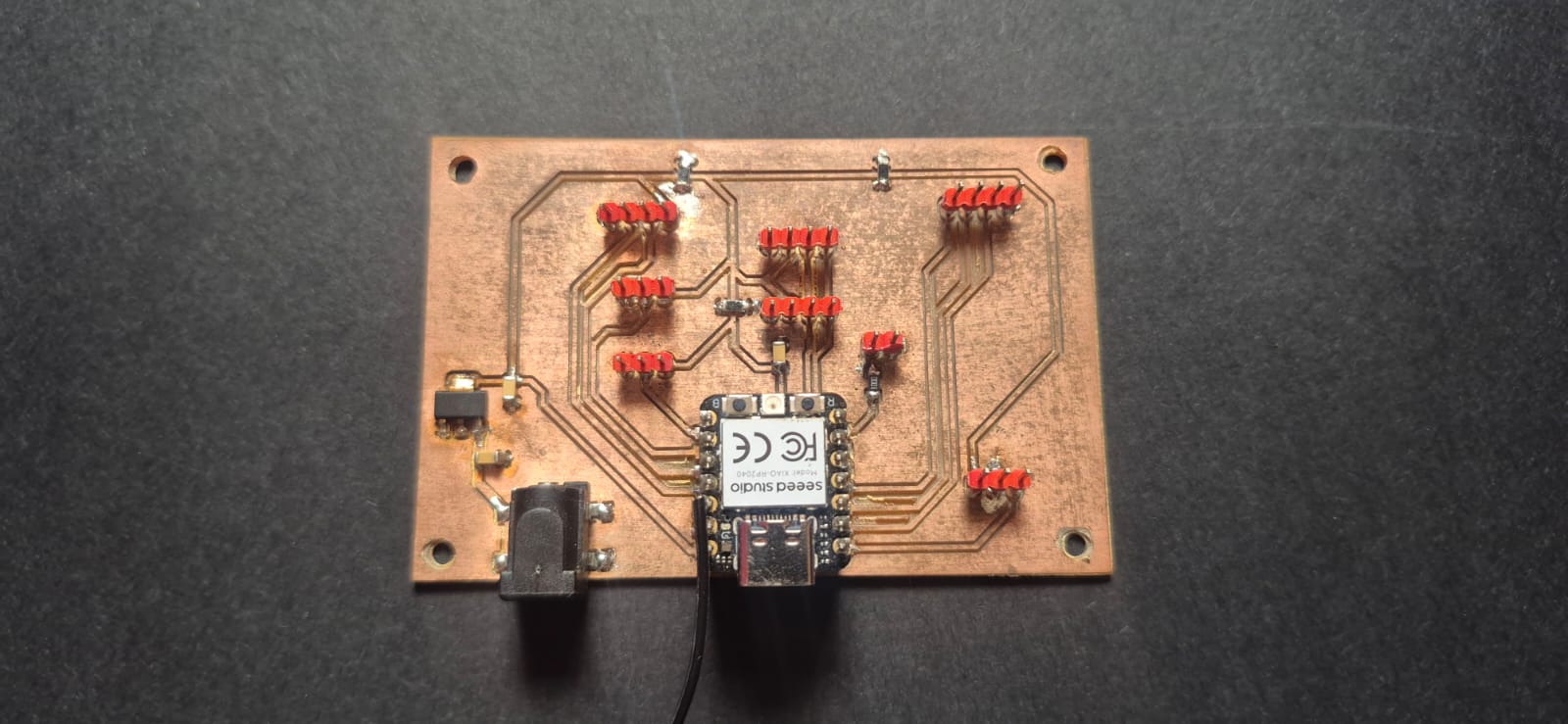
The first board is the one I designed during Week 6 and fabricated during Week 8. It contains a photoresistor (LDR) connected to analog pin A1, which continuously measures the ambient light level. In this project, this board acts as the I²C Main (Master) device. Based on the measured light level, it decides when to send commands to the other boards.
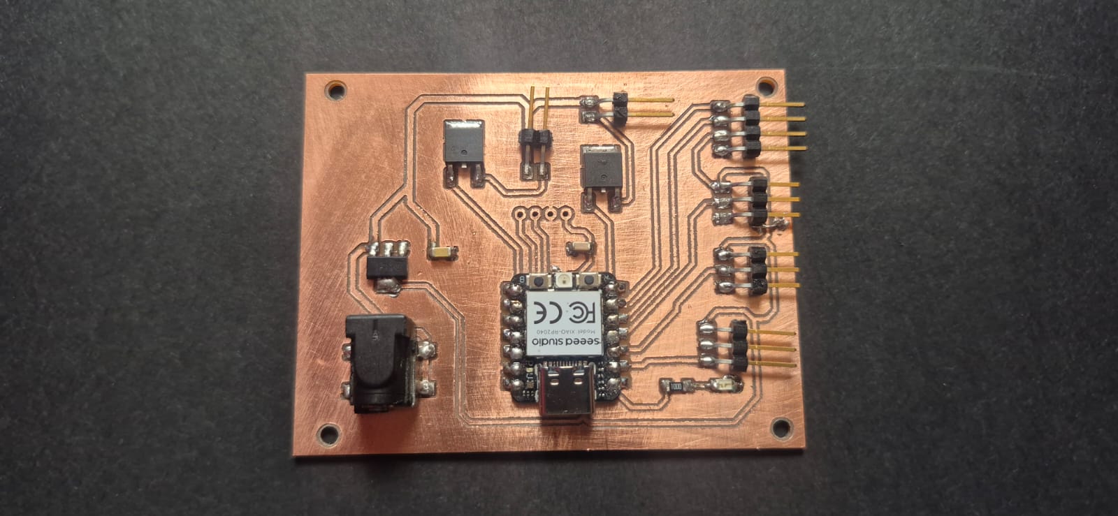
The second board is the main board that I designed and fabricated for my final project during Week 9. It controls a 12 V LED strip through a MOSFET connected to pin D9. This board operates as an I²C Secondary (Slave) device and waits for commands from the Main board. When it receives the ON command, the LED strip lights up using a PWM fade effect, gradually increasing and decreasing its brightness. When the OFF command is received, the LED strip turns off immediately.
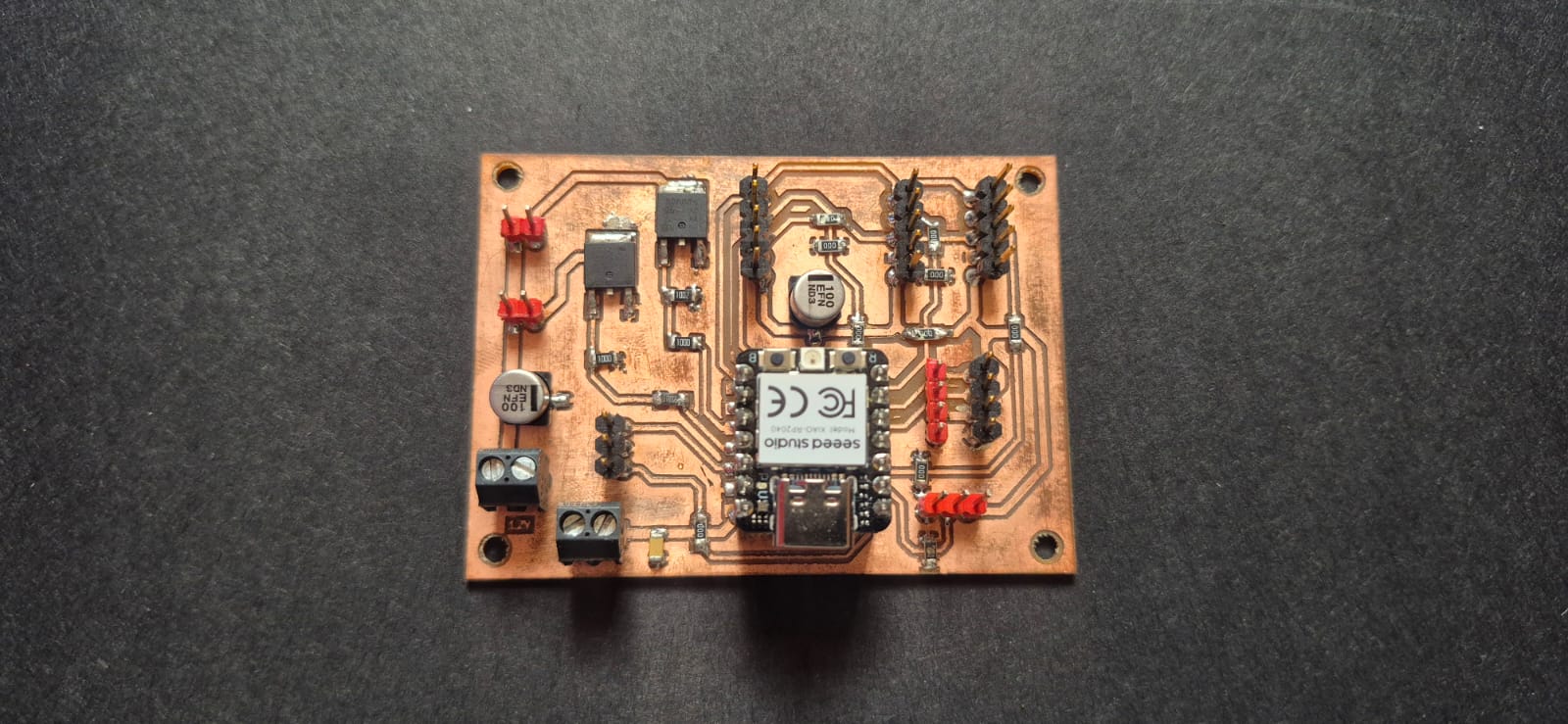
The third board is a board designed by Gevorg, with a buzzer connected to pin D6. For this assignment, it was used only as a standalone sound module and is not related to his main project. The buzzer board also operates as an I²C Secondary device and produces a sound only when it receives the appropriate command from the Main board.
To establish communication between the three boards, I connected the SDA, SCL, 3.3 V, and GND pins. The SDA and SCL lines form the I²C communication bus, while the common power supply and GND ensure that all boards operate with the same voltage reference, which is essential for reliable data transmission.
Since the project uses Seeed Studio XIAO RP2040 microcontrollers, the I²C pins must be assigned in software before initialization. Therefore, each program uses the Wire.setSDA() and Wire.setSCL() functions before calling Wire.begin(). Unlike traditional Arduino boards, the RP2040 does not have fixed I²C pins, so they must be defined explicitly in the code.
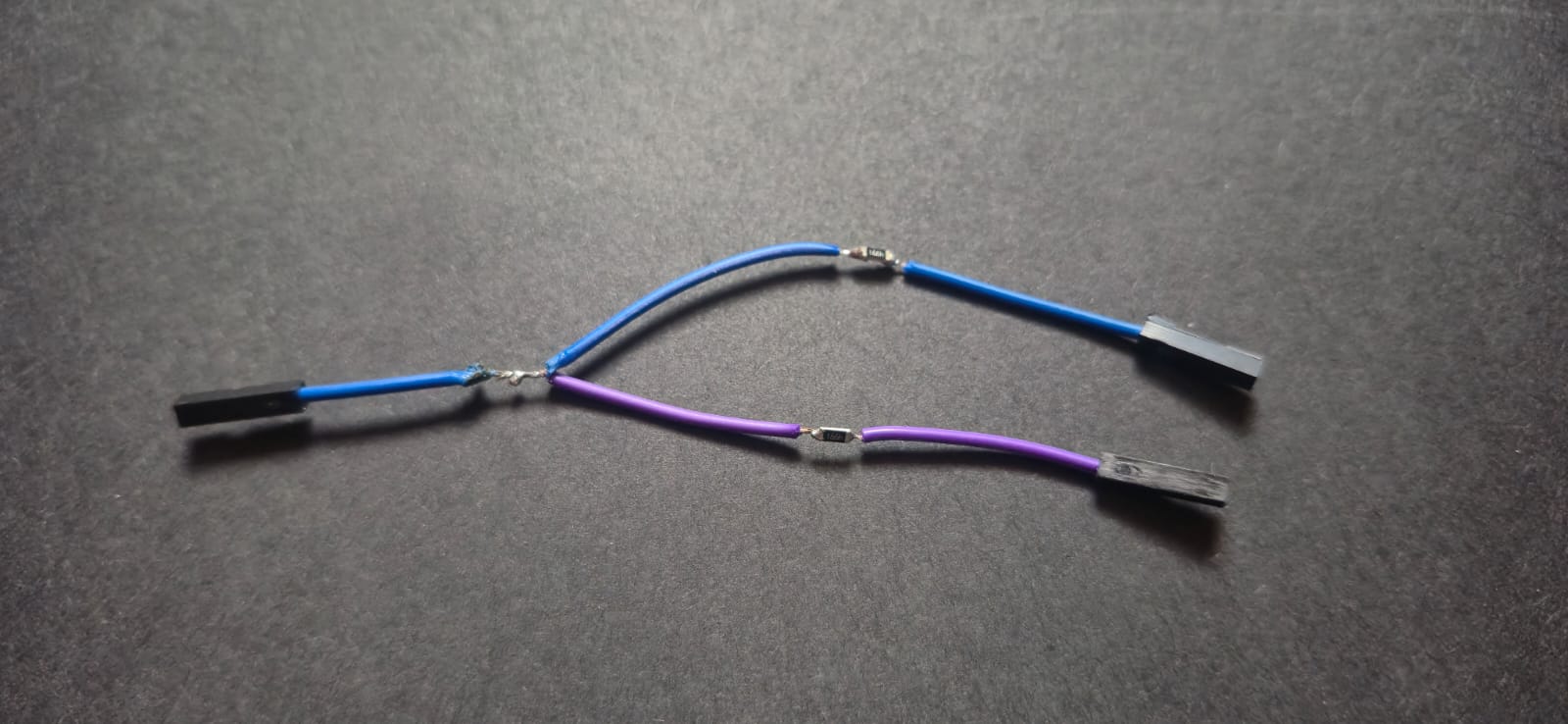
In addition, the I²C bus requires two 4.7 kΩ pull-up resistors for reliable communication. One resistor is connected between 3.3 V and SDA, and the other is connected between 3.3 V and SCL. These pull-up resistors ensure that both communication lines remain at a logic HIGH level whenever no device is actively transmitting data. Only one pair of pull-up resistors is required for the entire I²C bus, regardless of the number of connected devices.
LDR Board Code (Main)
#include <Wire.h>

#define LDR_PIN 26

#define LED_BOARD_ADDR 0x22
#define BUZZER_BOARD_ADDR 0x24

#define DARK_THRESHOLD 500

bool isDark = false;
unsigned long darkStartTime = 0;

void setup() {

  Serial.begin(9600);

  Wire.setSDA(6);
  Wire.setSCL(7);
  Wire.begin();

  Serial.println("LDR Master Started");
}

void loop() {

  int lightValue = analogRead(LDR_PIN);

  Serial.print("LDR value: ");
  Serial.println(lightValue);

  // Darkness (this LDR is wired so higher values indicate lower light)
  if (lightValue > DARK_THRESHOLD) {

    if (!isDark) {
      isDark = true;
      darkStartTime = millis();
    }

    unsigned long darkTime = millis() - darkStartTime;

    // Turn on the LED board
    Wire.beginTransmission(LED_BOARD_ADDR);
    Wire.write(0x01);
    Wire.endTransmission();

    // Activate the buzzer only during the first 3 seconds of darkness
    if (darkTime < 3000) {

      Wire.beginTransmission(BUZZER_BOARD_ADDR);
      Wire.write(0x01);
      Wire.endTransmission();

      delay(1000);
    }

  }
  else {

    isDark = false;

    // Turn off the LED board
    Wire.beginTransmission(LED_BOARD_ADDR);
    Wire.write(0x00);
    Wire.endTransmission();
  }

  delay(200);
}
LED Board Code (Secondary)
#include <Wire.h>

#define LED_PIN 4
#define LED_BOARD_ADDR 0x22

bool ledState = false;
int brightness = 0;
int fadeAmount = 5;

void receiveEvent(int howMany) {

  while (Wire.available()) {

    byte cmd = Wire.read();

    if (cmd == 0x01) {
      ledState = true;
    }
    else if (cmd == 0x00) {
      ledState = false;
      analogWrite(LED_PIN, 0);
    }
  }
}

void setup() {

  pinMode(LED_PIN, OUTPUT);

  Wire.setSDA(6);
  Wire.setSCL(7);

  // Initialize this board as an I²C Secondary device
  // with address 0x22
  Wire.begin(LED_BOARD_ADDR);

  // Register the function that will be called
  // whenever data is received from the Main board
  Wire.onReceive(receiveEvent);
}

void loop() {

  if (ledState) {

    // Generate a PWM fade effect
    brightness += fadeAmount;

    if (brightness <= 0 || brightness >= 255) {
      fadeAmount = -fadeAmount;
    }

    analogWrite(LED_PIN, brightness);

    delay(30);

  } else {

    // Turn the LED off immediately
    analogWrite(LED_PIN, 0);
  }
}
Buzzer Board Code (Secondary)
#include <Wire.h>

#define BUZZER_BOARD_ADDR 0x24
#define BUZZER_PIN 0

void receiveEvent(int howMany) {

  while (Wire.available()) {

    byte cmd = Wire.read();

    if (cmd == 0x01) {
      // Play a 2 kHz tone for 1 second
      tone(BUZZER_PIN, 2000, 1000);
    }
  }
}

void setup() {

  pinMode(BUZZER_PIN, OUTPUT);

  Wire.setSDA(6);
  Wire.setSCL(7);

  // Initialize this board as an I²C Secondary device
  // with address 0x24
  Wire.begin(BUZZER_BOARD_ADDR);

  // Register the function that will be called
  // whenever data is received from the Main board
  Wire.onReceive(receiveEvent);
}

void loop() {
}
I am working with three Seeed Studio XIAO RP2040 boards connected through the I²C communication protocol.

The first board is my main LED control board. It is connected to a 12V LED strip through a MOSFET, and the LED control signal is connected to pin D9. This board should work as an I²C Secondary device and receive commands from the Main board.

The second board contains an LDR sensor connected to the A1 analog pin. This board should work as the I²C Main device, continuously reading the light level and sending commands to the other boards depending on the measured value.

The third board contains a buzzer connected to pin D6. This board should work as another I²C Secondary device and activate the buzzer when it receives a command from the Main board.

Create Arduino code for these three boards using the Wire.h library. Use separate I²C addresses for each Secondary device, define SDA and SCL pins for the XIAO RP2040, and implement communication between the boards.
Testing
To verify the system, I repeatedly covered the photoresistor with my hand. Once the measured light value exceeded the defined threshold, the Main board simultaneously sent commands via I²C to both my LED board and Gevorg’s buzzer board. As a result, the LED strip started running with the fade effect, while the buzzer produced an audible signal, confirming that both Secondary boards correctly responded to the commands sent by the Main board.
Next, I removed my hand from the photoresistor. As the ambient light returned above the threshold, the Main board sent an OFF command to the LED board, causing the LED strip to stop operating.
The tests confirmed that the three independent boards successfully communicate over the I²C bus and perform their intended functions correctly.
Conclusion
In this assignment, I built a simple distributed system in which three independent XIAO RP2040 boards communicate using the I²C protocol. The LDR board fabricated during Week 8 acts as the Main device and continuously monitors the ambient light level. My main board controls the 12 V LED strip, while Gevorg’s buzzer board provides an audible notification.
Using the I²C protocol made it possible to distribute different functions across multiple microcontrollers while maintaining simple and reliable communication. This modular approach makes the system easier to expand, since additional devices can be connected to the same I²C bus in the future without changing the overall system architecture.