Week 3. Computer-Controlled Cutting
Group Assignment
This week, the work began in a group format, during which we first became familiar with the structure of the laser cutting machine and its safety rules. During the practical phase, we performed inspection and alignment of the laser system’s optical path and reviewed the machine’s main technical parameters before starting the experiments. Throughout this process, we were guided by Aram Pichikyan, a lecturer at the Gyumri branch of the Armenian State Academy of Fine Arts.
Laser System Used and Technical Specifications
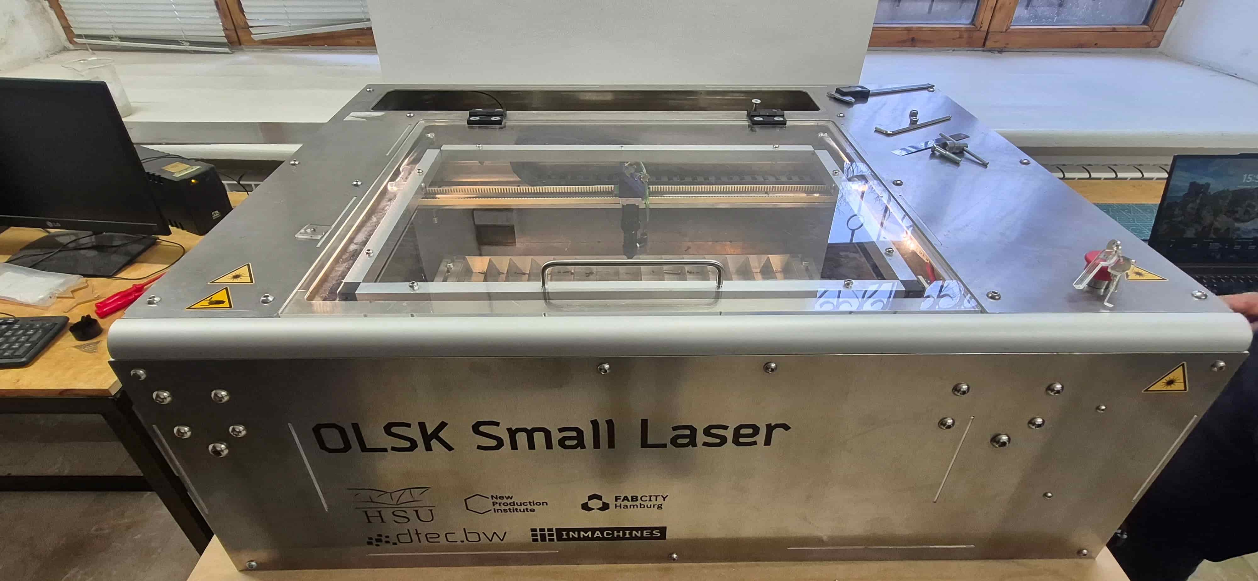
During the group assignment, we used a 40W CO₂ laser cutter, which is designed for processing non-metallic materials. This type of laser is commonly used for cutting and engraving wood, plywood, MDF, acrylic, and cardboard, providing sufficient precision and stable results.
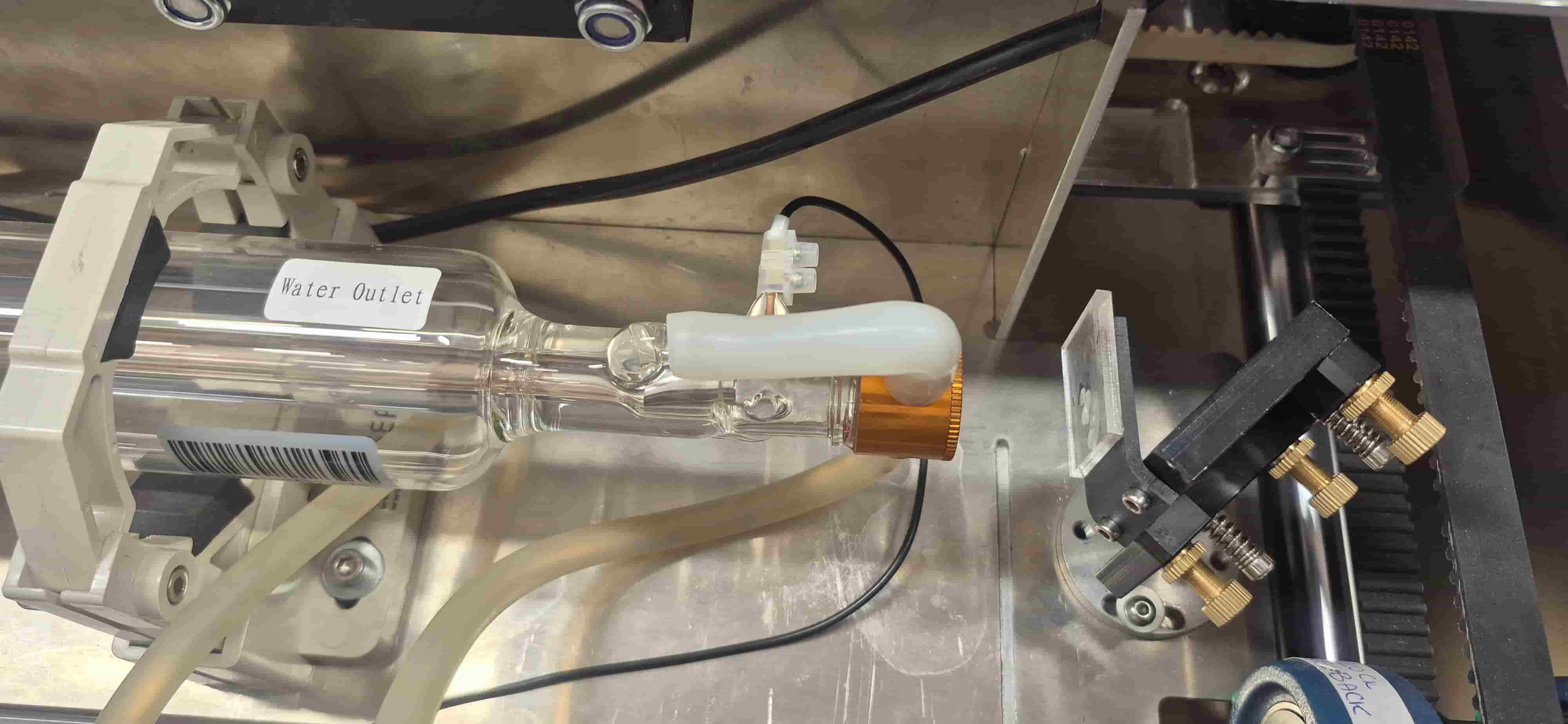
The system is based on a CO₂ gas laser source with a typical wavelength of approximately 10.6 µm, making it particularly suitable for processing organic materials. The laser beam is controlled by a digital system that allows precise adjustment of speed, power, and cutting/engraving modes.
The main technical specifications of the machine we used are listed below:
| Parameter | Description |
|---|---|
| Laser type | CO₂ laser |
| Laser power | 40W |
| Wavelength | ~10.6 µm |
| Working area | 600 × 400 mm |
| Maximum travel speed | up to 1000 mm/s |
| Control system | 32-bit Teensy 4.1 |
| Firmware | GRBL-HAL |
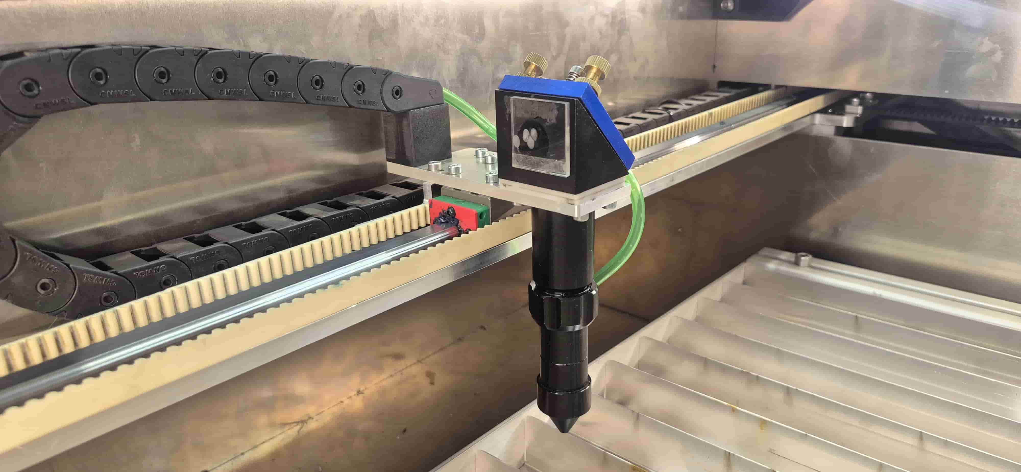
| Motion system | Linear rails and shaft-based mechanism |
| Bed structure | Aluminum slat bed (allows smoke and debris extraction) |
| Positioning system | High-repeatability linear guide system |
This system allows both clean cutting and precise engraving, depending on the settings of power, speed, and focus. During our experiments, we mainly worked with 3 mm thick plywood to study the effect of different parameters.
Safety Rules
Before operating the laser cutter, we reviewed the machine’s safety rules and checked its operational condition. We ensured that the ventilation and exhaust systems were working properly, and that the mirrors and lens were clean.
During operation, we always made sure that the machine was never left unattended, as there is a risk of fire, especially when working with wood-based materials. We also followed the principle that the lid must remain closed throughout operation to protect against possible reflections of the laser beam.
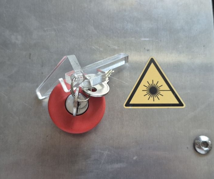
In addition, the presence of an emergency stop button is very important, as it allows the machine to be stopped immediately when necessary.
We also paid attention to material selection, avoiding materials such as PVC and vinyl, which can release toxic gases when processed.
These measures together ensured a safe, controlled, and stable working process throughout all experiments.
Optical Path Alignment
In the next stage, the laser beam alignment process was carried out to ensure the precise operation of the system.
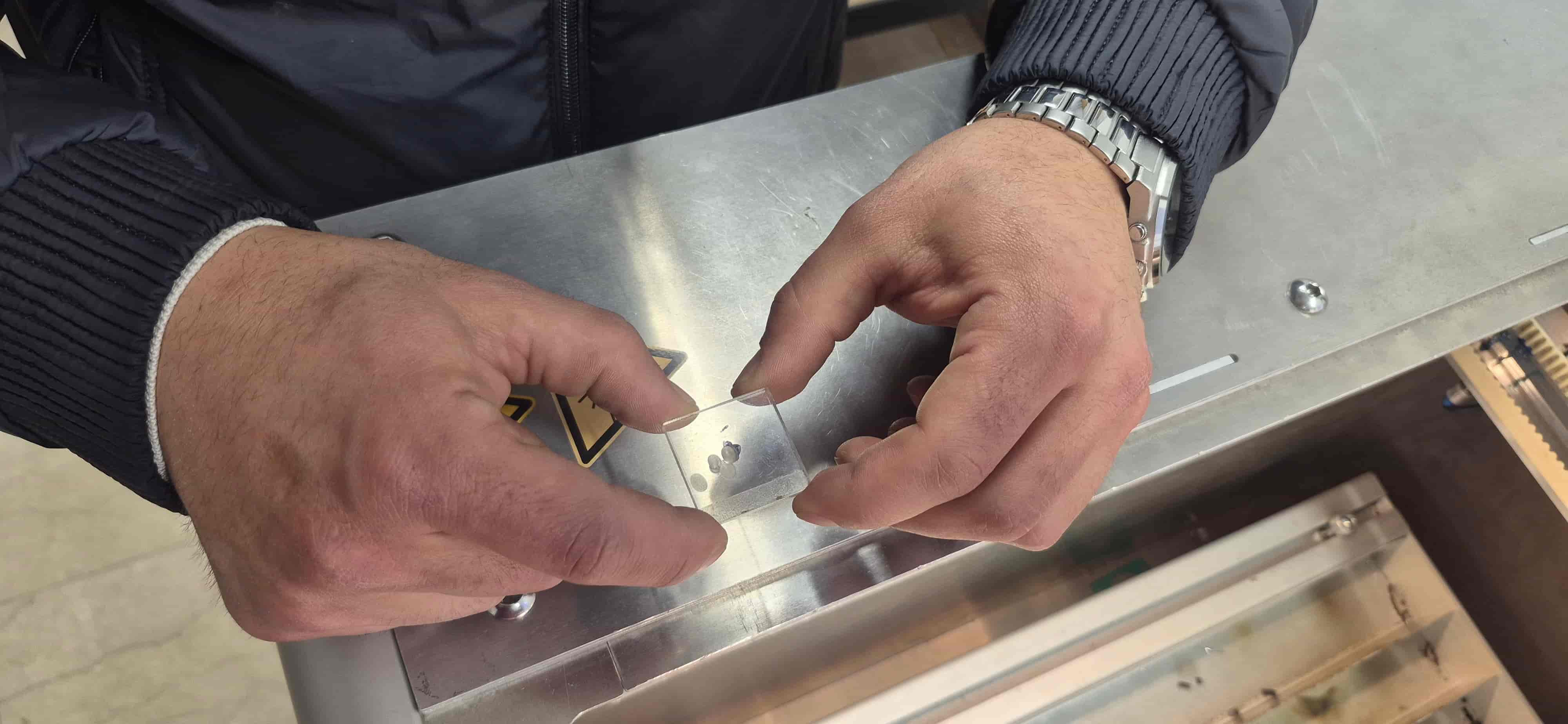
First, the position of the laser beam was checked using a transparent acrylic plate, since this material allows the impact point of the beam to be clearly visible without producing excessive smoke.
Acrylic was chosen instead of paper because a paper test could have burned the surface and generated smoke that might reach the mirrors, potentially damaging or contaminating the machine. Based on the obtained marks, the beam position was evaluated at different points.
Afterward, the transmitting mirrors were adjusted.
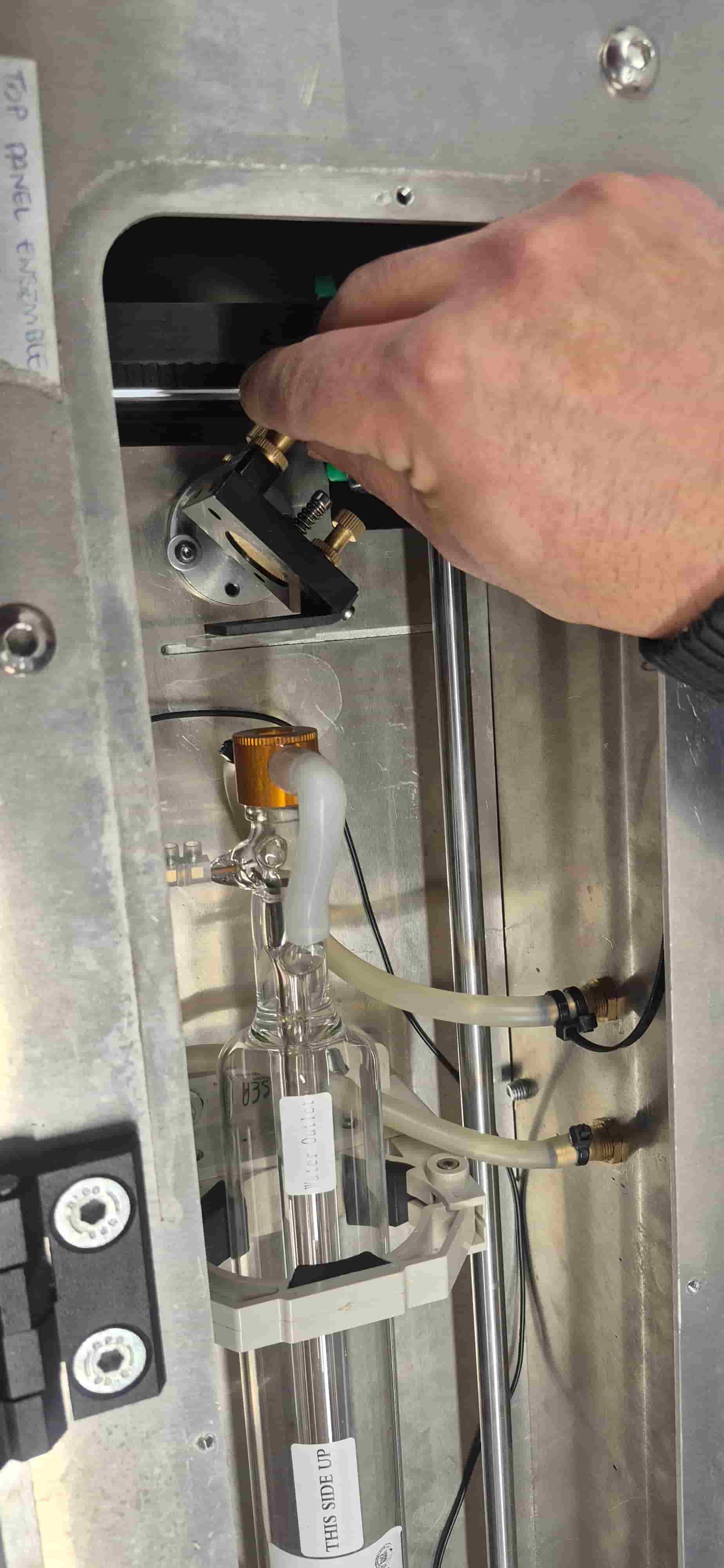
Using the alignment screws on the mirror modules, the beam direction was carefully corrected to ensure that it passed through the center of the optical path and accurately reached the laser head.
The adjustment process was repeated until the test marks matched the intended centers. As a result, it was confirmed that the optical system was properly aligned and the machine was ready for safe and precise operation.
Focus Characterization
To achieve clean and precise cuts, it is important that the laser is properly focused on the material surface.
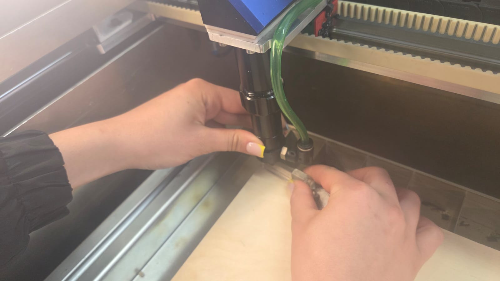
In our machine, the lens has a standard focal length of 50.8 mm (2 inch). Focus adjustment was carried out using a 6 mm calibration tool, which is placed on the material surface, and the laser head is lowered until it rests on this tool.
This method ensures the correct working distance between the nozzle and the material.
More detailed information about the group work can be found on the group assignment page.
Axis Calibration
During the Kerf test, we noticed that the dimensions of the cut parts did not correspond to the expected results. As a result of the measurements, it turned out that the X and Y axes of the laser cutter were not calibrated correctly, as a result of which the resulting dimensions were larger than designed. Additional measurements and calculations were performed to study the problem, the details of which are presented on the Group Assignment page.
Temporary Adjusments
Before changing the main device settings, scaling corrections were applied in the LightBurn program. Thanks to this, it was possible to compensate for the axis error and obtain more accurate cuts. However, this solution was temporary, since for each new file it was necessary to re-apply the same corrections.
Final Calibration
Aram Pichikyan assisted us in the final calibration process. Using 8GRBL* settings, the device axes were recalibrated so that the motor steps corresponded exactly to the actual distance traveled. This change resolved the issue at the device level and eliminated the need for additional adjustments in LightBurn. After calibration, the device returned to its normal and accurate operation. Detailed calculations and steps taken are presented on the Group Assignment page.
Kerf Measurement
After completing the axis calibration, we performed a kerf measurement test using a test sample consisting of 11 rectangles (each 10 mm wide) that were cut as one continuous geometry.
Theoretically, the total length of the sample should be 110 mm, but the measurements resulted in 107.77 mm.
To calculate the kerf value, we first found the total dimensional loss:
$$ 110 - 107.77 = 2.23 \text{ mm} $$
Since the sample consisted of 11 rectangles, we get 10 internal cuts, and the two outer edges together give another full kerf width. That is, the total loss corresponds to 11 kerf widths.
Therefore, we calculated the kerf using the following formula:
$$ Kerf = \frac{110 - 107.77}{11} = \frac{2.23}{11} \approx 0.203 \text{ mm} $$
Thus, we adopted the laser kerf value of 0.20 mm and used it during further parametric design, slot size calculation, and connection adjustment.
Cutting Test
Plywood Cutting Test
This week, Gevorg and I carried out a laser cutting experiment on 3 mm thick plywood. The goal was to evaluate the effect of different processing parameters and identify the most suitable settings for the subsequent fabrication process.
We began by focusing on the cutting process and conducted a cutting test to determine the optimal cutting parameters for the material. In particular, we investigated how the laser movement speed influences the cutting depth, edge quality, and overall cutting performance.
The test file was prepared in LightBurn software, where each square was assigned a different color. Each color corresponded to a different speed parameter, allowing us to test multiple cutting conditions within the same file and easily compare the results. This approach significantly accelerated the testing process and allowed us to observe the effect of different settings on a single sample.
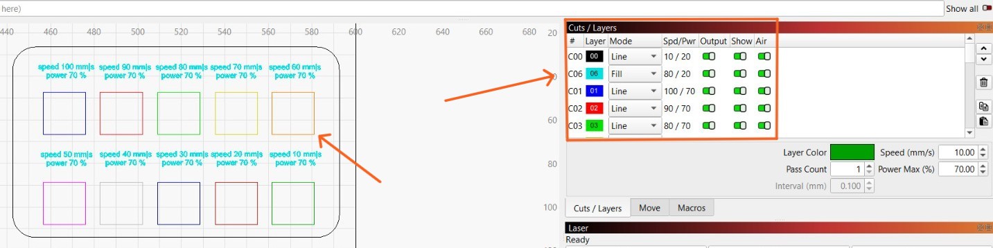
During the experiment, the power was kept constant at 70%, while the speed was varied from 100 mm/s to 10 mm/s. This allowed us to study the effect of a single variable—speed—without interference from power changes.
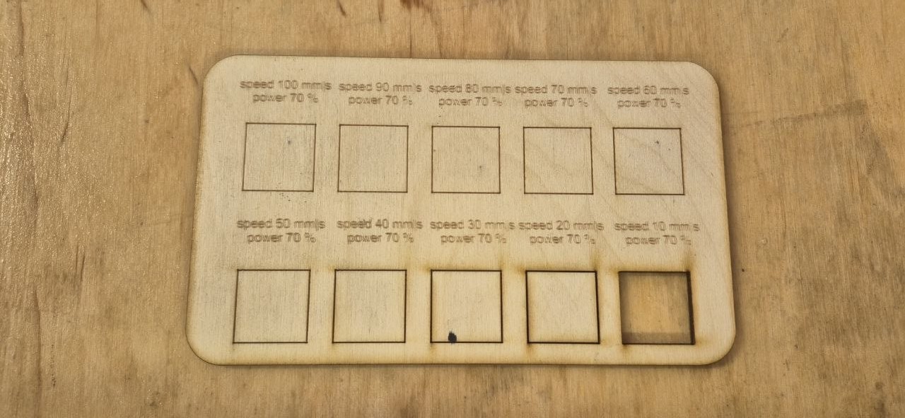
During the test, we observed that changes in speed had a significant impact on cutting quality.
- At high speeds (100–70 mm/s), the laser moved too quickly across the material surface, so it did not have enough time to cut through the material completely. As a result, some sections were only partially cut or did not cut through at all.
- At medium speeds (60–30 mm/s), more balanced results were achieved. The cuts were cleaner, the edges were smoother, and burn marks were relatively minimal.
- At low speeds (20–10 mm/s), the laser remained on the material longer, resulting in greater energy transfer. This ensured complete cutting through the 3 mm thick material, but also caused more noticeable burnt edges and darkening.
During the experiment, we paid attention not only to whether the laser could cut through the material, but also to cut cleanliness, edge condition, and surface changes. This test helped us understand which speed range could produce clean and high-quality cuts on 3 mm plywood.
After comparing the results, we found that the best cutting performance was achieved with speed 10 mm/s and power 70%, as this setting allowed the laser to fully cut through the material and produce a complete, reliable cut suitable for the following fabrication process.
Acrylic Cutting Test
Following the plywood experiments, we conducted a similar laser cutting and engraving test on 2.7 mm thick organic glass (acrylic) to investigate the effects of different speed and power settings and identify the optimal processing parameters for this material.
The test file was prepared in the software LightBurn. Each square in the file was assigned a separate color, and each color corresponded to different speed and power values. This method made it possible to compare multiple parameters within a single test and quickly evaluate their effect on processing quality.
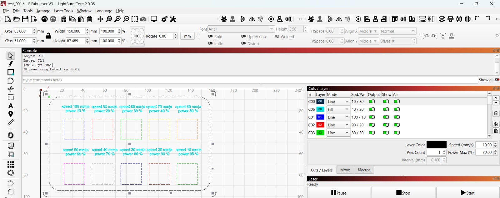
Different speed and power values were predefined for each square in the test file, ranging from 100 mm/s speed with 10% power to 10 mm/s speed with 95% power. This allowed us to compare the impact of various settings during a single experiment and assess their effectiveness in the processing of organic glass.
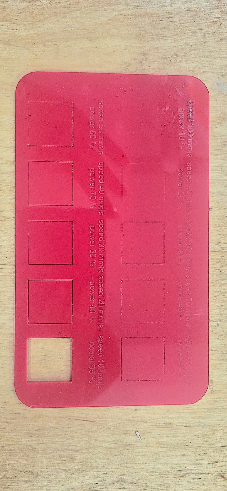
The results showed that both speed and power significantly affected the cutting quality of the acrylic. Higher speeds resulted in incomplete cuts, while lower speeds and higher power produced cleaner and more reliable cuts. The best results were achieved with low speed and high power settings.
Engraving Test
Plywood Engraving Test
After the cutting test, using the same experimental method, we also conducted an engraving test on 3 mm thick plywood to evaluate how changes in speed affect the engraving depth, darkness, and overall quality.
The test file was prepared in LightBurn using the same approach as in the cutting test. Each square was assigned a different color, and a specific speed parameter was defined for each color. However, unlike the cutting test, the engraving test was performed using Fill Mode, which allowed the laser to scan and engrave the entire surface of each square. This approach made it possible to compare how engraving darkness, depth, and surface quality changed at different speeds.
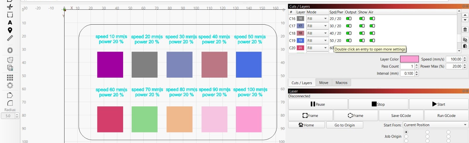
During the experiment, the power was kept constant at 20%, while the speed was varied from 100 mm/s to 10 mm/s. This allowed us to evaluate the influence of speed independently, without the effect of changing power settings.
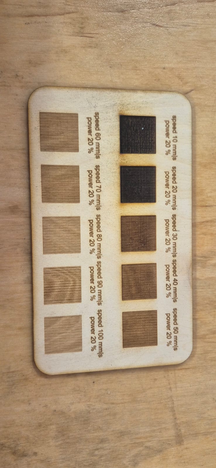
The results showed that engraving speed had a significant impact on engraving quality:
- At higher speeds (100–60 mm/s), the laser moved quickly across the material surface, resulting in lighter and shallower engravings because the laser had less interaction time with the material.
- At medium speeds (50–30 mm/s), more balanced results were achieved. The engravings appeared clearer, with improved darkness and contrast.
- At lower speeds (20–10 mm/s), the laser remained on the material for a longer period, increasing the thermal effect and producing darker and deeper engravings. However, some areas also showed more noticeable burn marks.
Throughout the experiment, attention was given not only to engraving visibility but also to surface uniformity, contrast, and the presence of burn marks. This test helped identify the speed range capable of producing the highest-quality engraving on 3 mm plywood.
After comparing the results, the most suitable engraving parameters were selected for the subsequent fabrication process based on engraving clarity, contrast, and overall surface quality.
Acrylic Engraving Test
After determining the most suitable engraving parameters for 3 mm plywood, the same engraving procedure was carried out on 2.7 mm acrylic (organic glass). By keeping the laser power constant and varying only the speed, it was possible to compare how a different material responds to the same engraving conditions and to identify the optimal parameters for acrylic fabrication.
After completing the cutting tests, we also performed an engraving test on 3 mm thick acrylic (organic glass) to evaluate how laser speed affects engraving quality, visibility, and contrast.
The test file was prepared in LightBurn. Each square was assigned a different color, and each color corresponded to a different speed value. The engraving was performed using Fill Mode, allowing the entire surface of each square to be engraved and making it easier to compare the results.
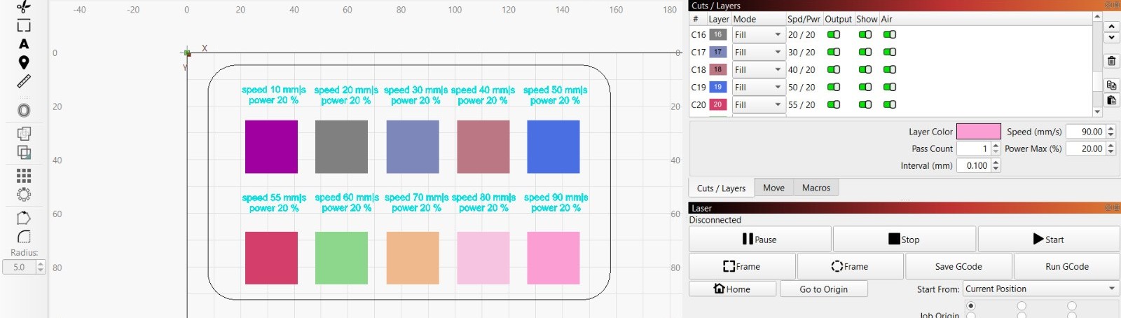
During the experiment, the laser power was kept constant at 20%, while the speed was varied from 90 mm/s to 10 mm/s. This approach allowed us to evaluate the effect of speed alone without the influence of power changes.
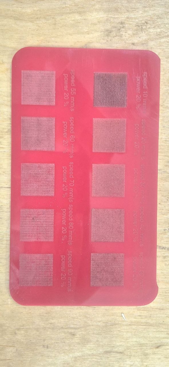
The results showed that speed had a significant impact on engraving quality.
- At speeds of 90–70 mm/s, the engravings appeared lighter and more superficial because the laser interacted with the material for a shorter period of time.
- At speeds of 60–40 mm/s, more balanced results were achieved. The engravings became more visible, and the surface appeared more uniform.
- At speeds of 30–10 mm/s, the laser had a stronger effect on the material, producing more pronounced, deeper, and higher-contrast engravings. However, at the lowest speeds, some areas showed signs of thermal effects.
The results helped us identify the most effective engraving parameters for acrylic and apply them in the subsequent fabrication process.
Vinyl Cutting
About our Vinyl Cutter
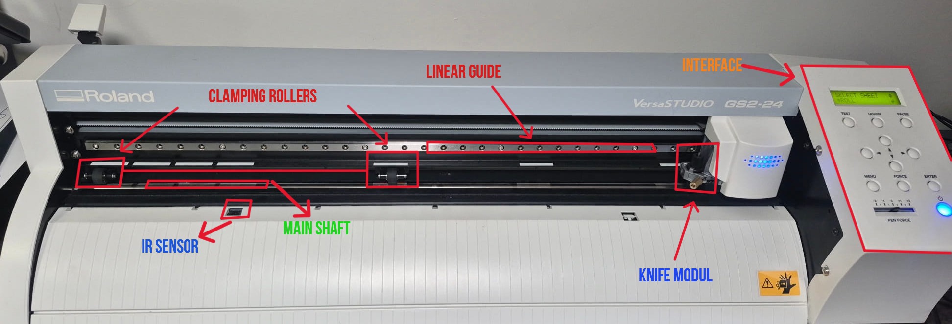
In our laboratory, we use the Roland VersaStudio GS2-24, a vinyl cutting machine designed for precise cutting of vinyl, heat-transfer films, and other thin materials. The machine features a compact design, stable performance, and high cutting accuracy, making it suitable for graphic design, labeling, and decorative applications.
| Parameter | Description |
|---|---|
| Device model | Roland VersaStudio GS2-24 |
| Cutting Width | 22.9 in (584 mm) |
| Material Width | 1.97 – 27.5 in (50 – 700 mm) |
| Maximum Cutting Speed | 0.39 – 33.4 in/s (10 – 850 mm/s) |
| Cutting Force | 30 – 500 gf |
| Repetition Accuracy | ≤ 0.1 mm |
| Interface | USB 2.0, Ethernet |
| Power Supply | AC adapter 100–240 V → 24 V DC 2.7 A |
| Dimensions | 860 × 319 × 235 mm |
Here are the components of a vinyl cutter and how it is built.
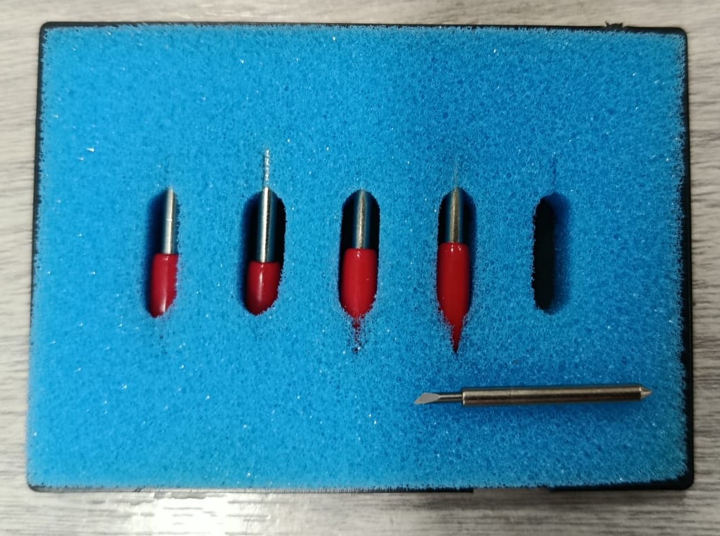
And this is the blade that cuts our material.
Testing, Setting knife force
When I turned on the machine, it performed a home position setup, and the display immediately showed the function to choose the type of sheet. There are three options available:
-
Roll
-
Piece
-
Edge
Since I am going to do a test, I decided to use the material in roll form. To do this, I place the roll between the clamping rollers and the main shaft, clamp the rollers onto the material, and then select roll* in the sheet selection menu.
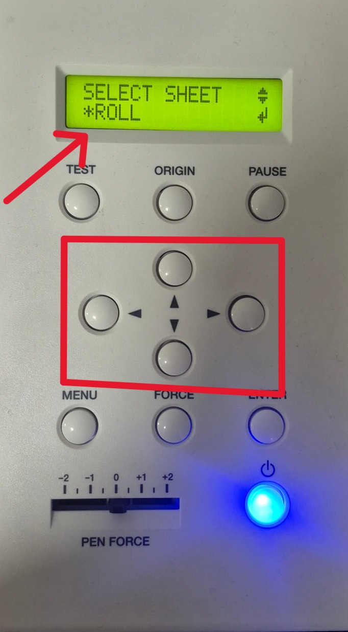
After selecting Roll, the machine does not measure the full length, but only detects the width of the material using the sensors located at the front and back of the cutting area. The length is considered unlimited, as the material is fed continuously from the roll.
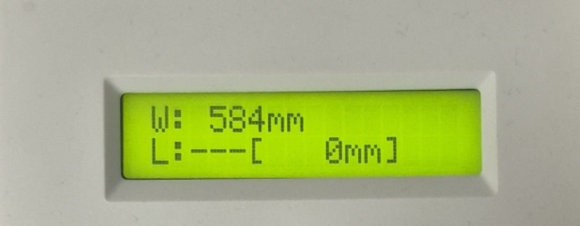
For example, the machine detected the material width as W: 584 mm. Even though the real width of the vinyl is 600 mm, the machine keeps a safe margin of about 3–3.5 cm on both sides to avoid cutting outside the usable area or damaging the blade.
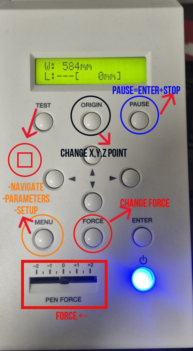
To achieve accurate cutting results, two main parameters must be set:
-
Force
-
Speed
These parameters are highly dependent on the type and condition of the vinyl. Room temperature and storage conditions play a significant role, because vinyl can deform depending on temperature. As a result, the same vinyl may not be cut accurately with the same force and speed settings if it has been stored in different environmental conditions.
Therefore, it is always necessary to run test cuts before starting the final job and adjust the force and speed accordingly.
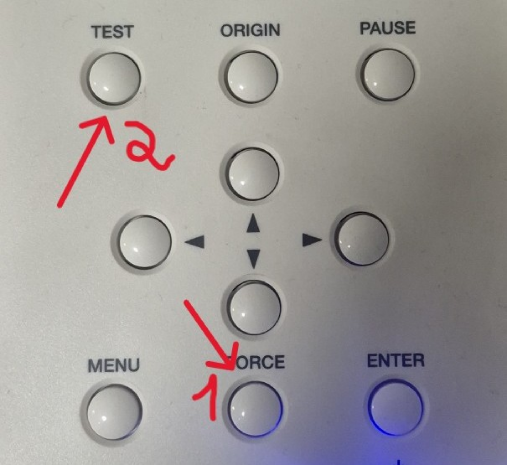
Time to set the force for the knife. To do this, press the “Force” button, choose the force, and hold the “Test” button.
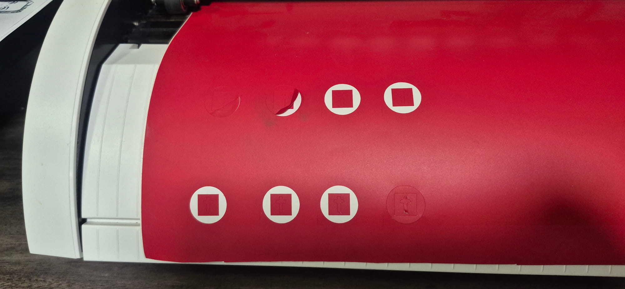
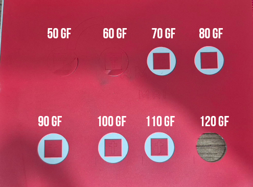
I tried cutting my material at several depths to determine the correct cutting depth. I started from 50 gf up to 120 gf. From 80 gf, the cut was already ideal, but I continued testing. At 120 gf, the material was cut all the way through.
Fabrication of My Design
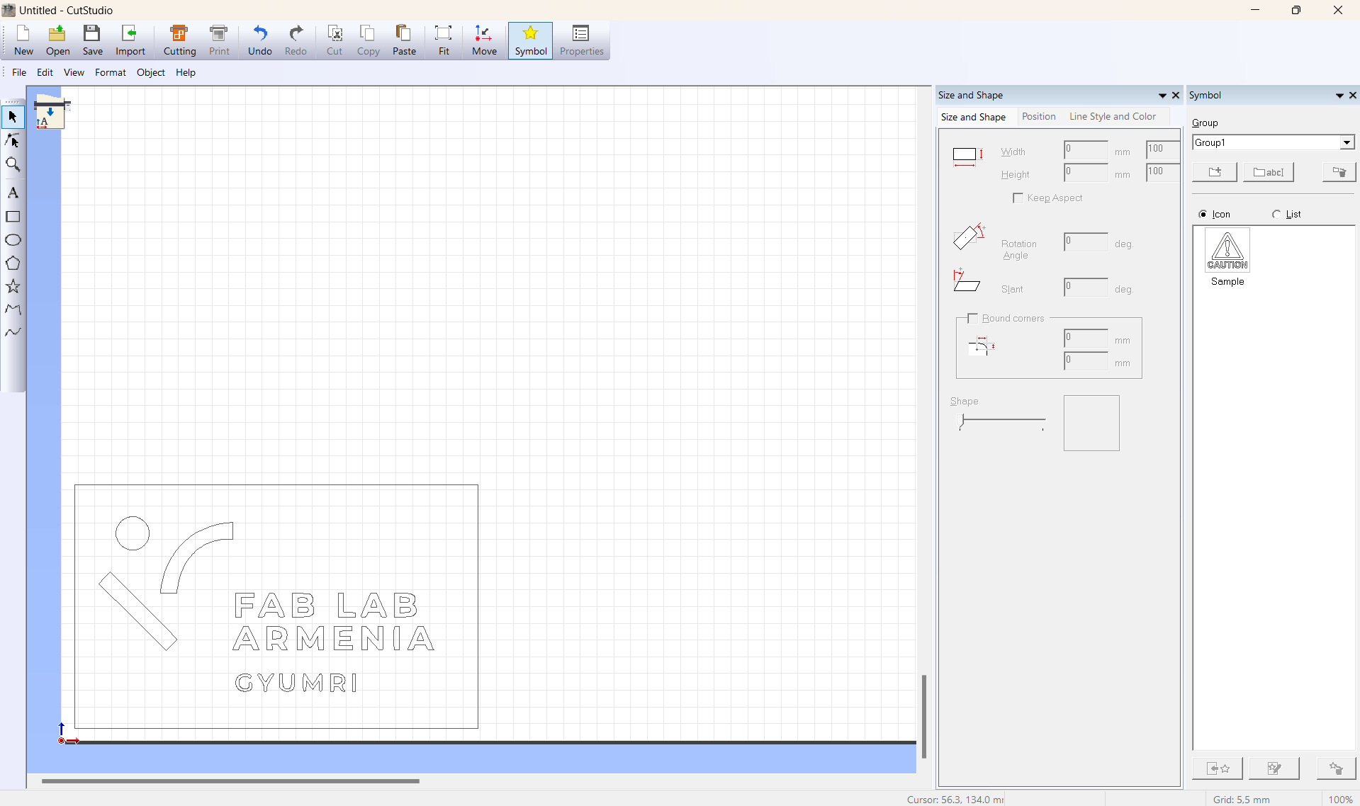
After completing these steps, I imported the file of my designed artwork into Cut Studio, the software used to operate and control our cutting machine.
Then, I set the dimensions of my design.
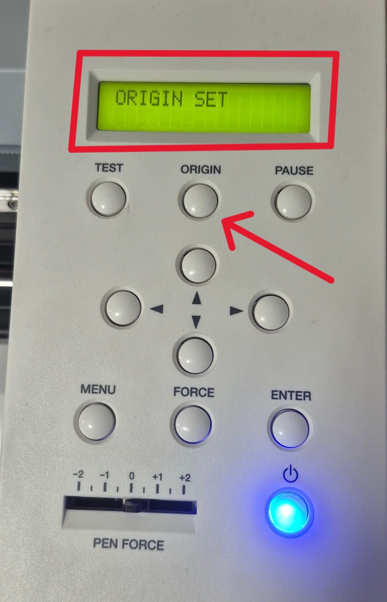
I move the machine head to the area of the material where I want the cutting to start, then press and hold the Origin button so the machine recognizes that point as the starting position.
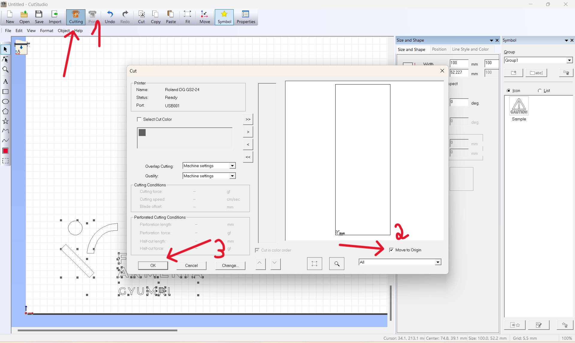
In the software, when I select Cutting, a window opens where I choose Move to Origin so the machine cuts from the position I specified.
And then I start the cutting process.
After cutting, I apply transfer tape onto the material so I can lift and separate the parts I need.
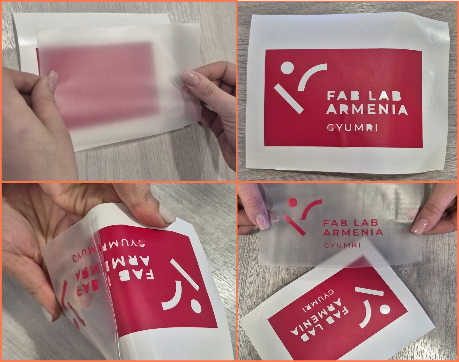
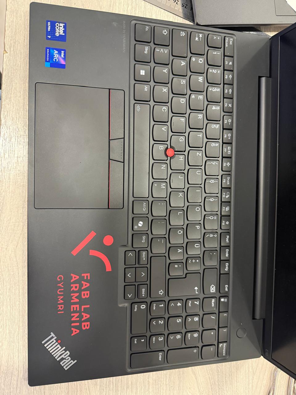
And then I decide where to place it on my computer.
Laser Cutting
Laser Cut Kerf Test Drawing
Before assembling the construction kit, a test was conducted to determine the amount of material removed by the laser during cutting (kerf). Since the material thickness is 4 mm, it was necessary to determine the joint size that would ensure a tight and accurate fit.
For this purpose, a parametric test model was created in FreeCAD, containing slots ranging from 3.00 mm to 2.50 mm with a 0.05 mm step. This makes it possible to precisely identify the optimal joint dimension.
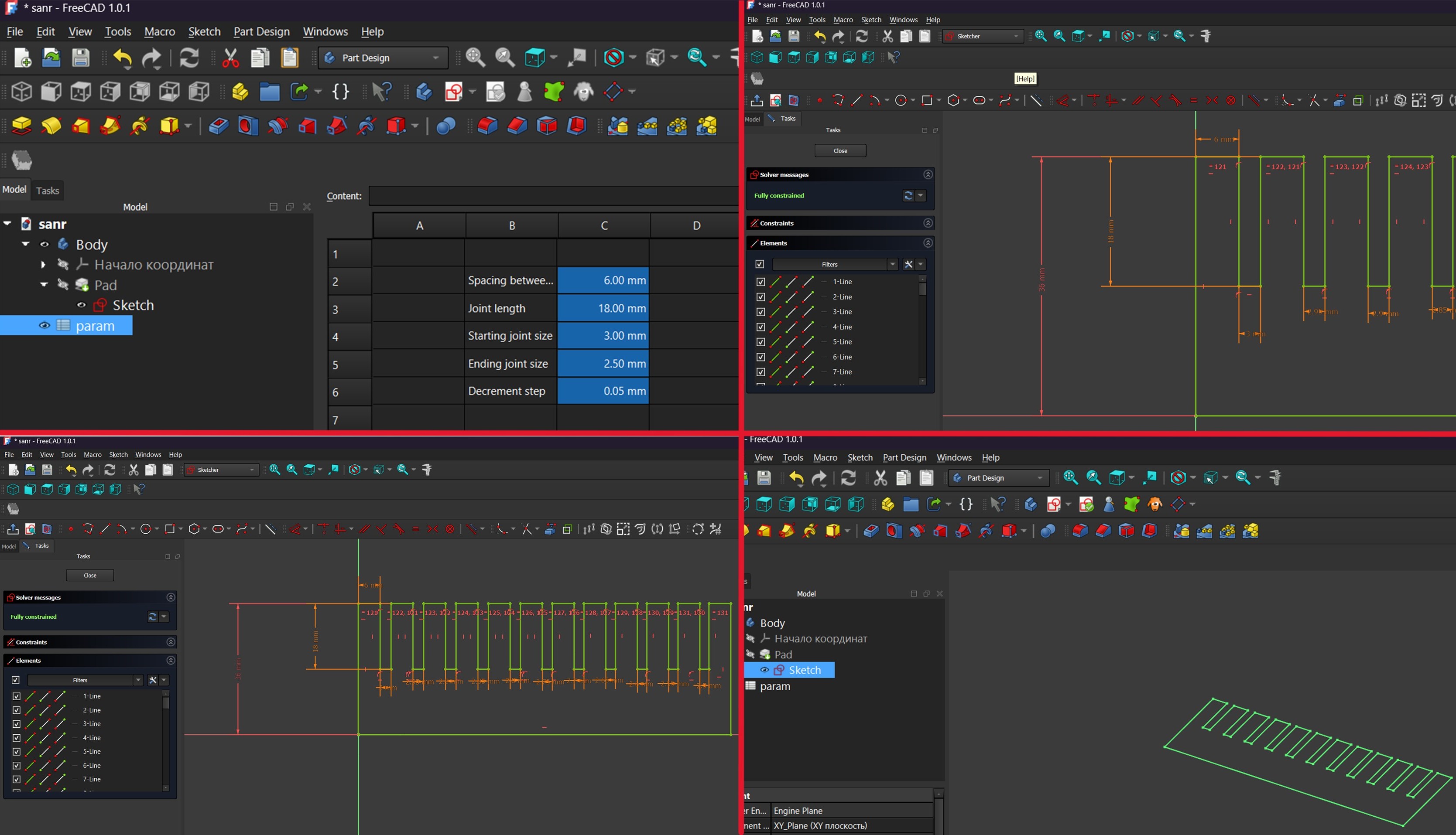
After that, the file was exported as a DXF file.
Since our laser machine operates with LightBurn software, the design file was exported in a compatible format and prepared for cutting.

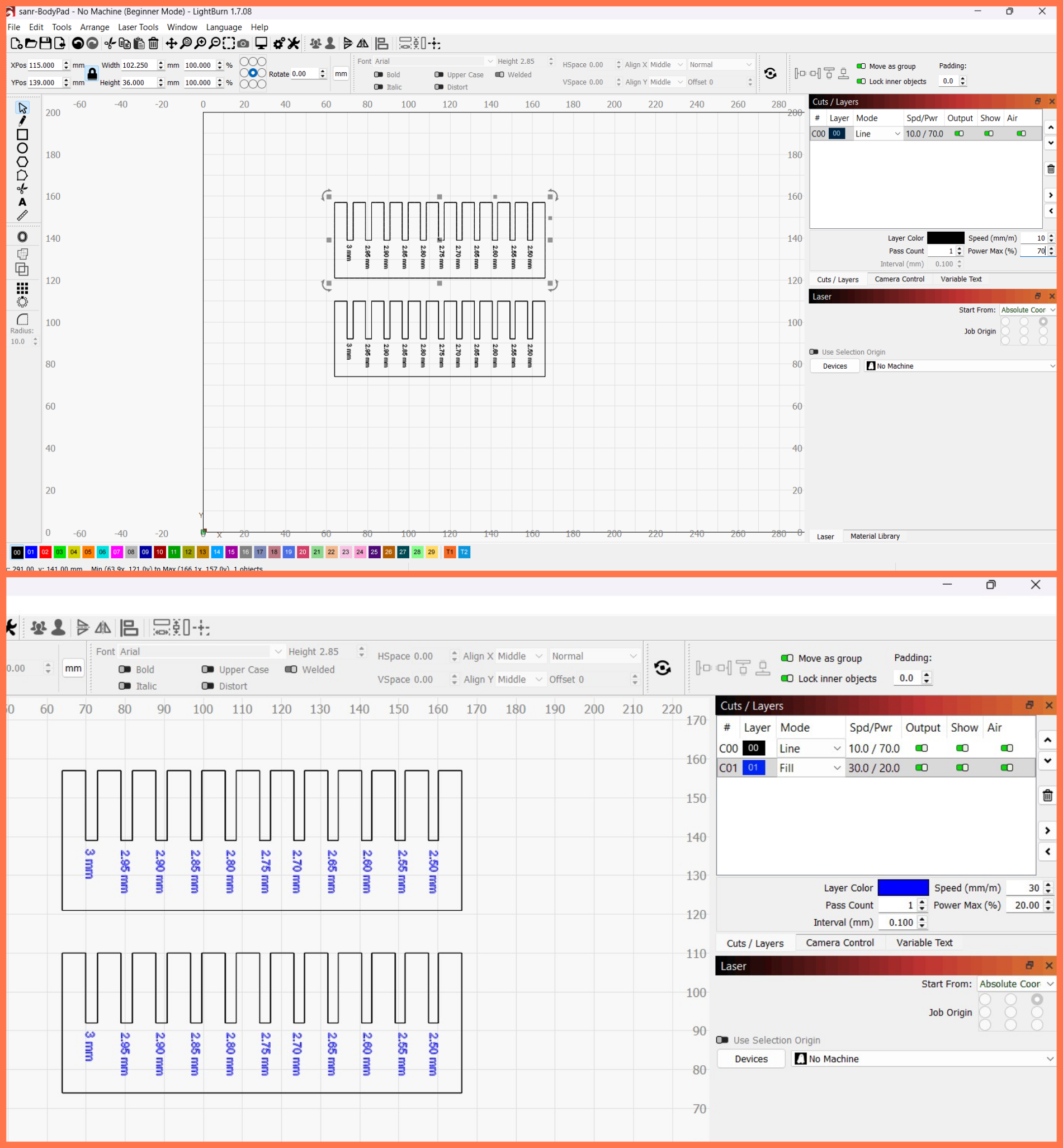
The DXF file was opened in LightBurn. Text was added to the drawing, and the design was duplicated. The cutting areas were then selected and their parameters were assigned. After that, the engraving regions were defined and their corresponding settings were configured. Finally, the cutting process was executed.
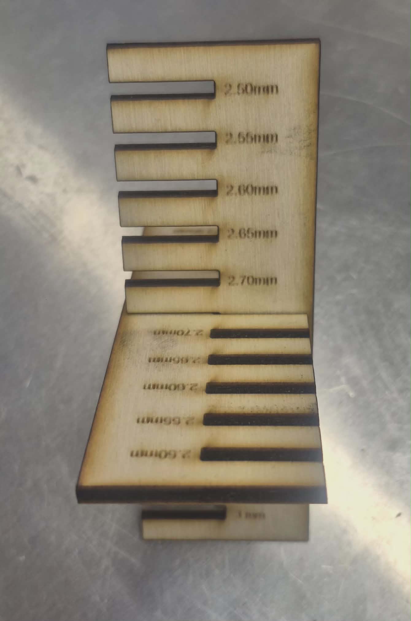
After cutting, the joints were tested sequentially by fitting them into each other. The best fit was achieved at 2.75 mm, which provided the optimal balance between tightness and ease of assembly.
Based on the fitting test results, it was determined that the optimal joint dimension was 2.75 mm, which provided the best balance between tightness and ease of assembly. Comparing this value with the nominal design range led to the conclusion that the effective kerf of our laser cutting machine is approximately 0.25 mm. This value was therefore taken into account for adjusting the final design parameters to ensure accurate and reliable joints.
Parametric design part-Freecad
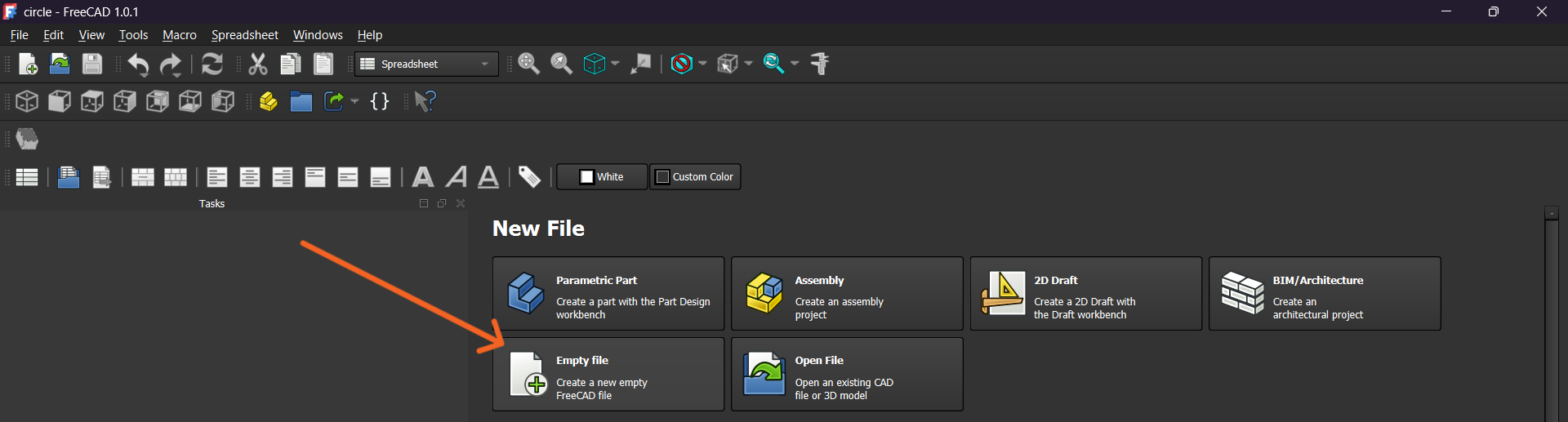
I opened FreeCAD and created a new project.
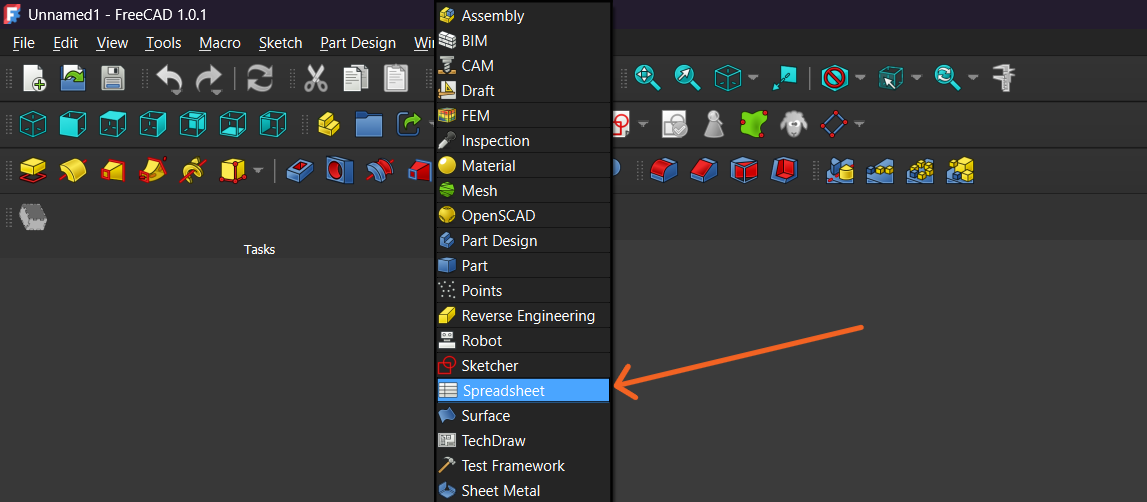
I switched to the Spreadsheet Workbench and created a new spreadsheet.
In the spreadsheet, I defined the main dimensions and parameters of the project. This allows the design to remain fully parametric and easy to modify.
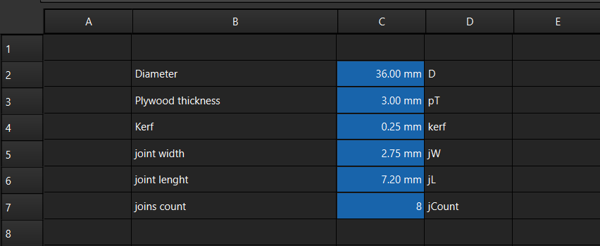
I defined parameters such as the diameter, plywood thickness, kerf, joint width, joint length, and number of joints. These values control the geometry of the model and allow quick modifications without recreating the design.
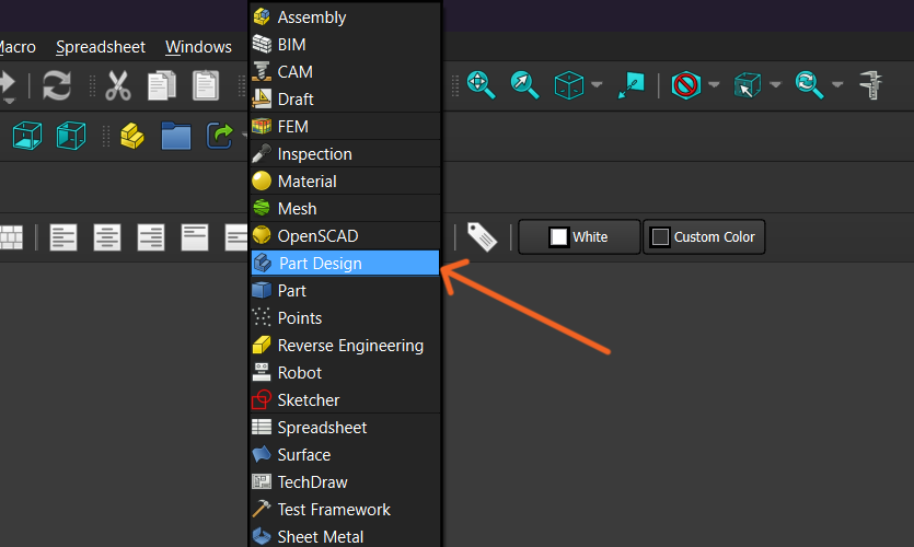
I switched the workbench to Part Design to begin creating the 3D model.
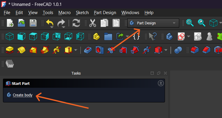
A new Body was created to contain all the features of the design.
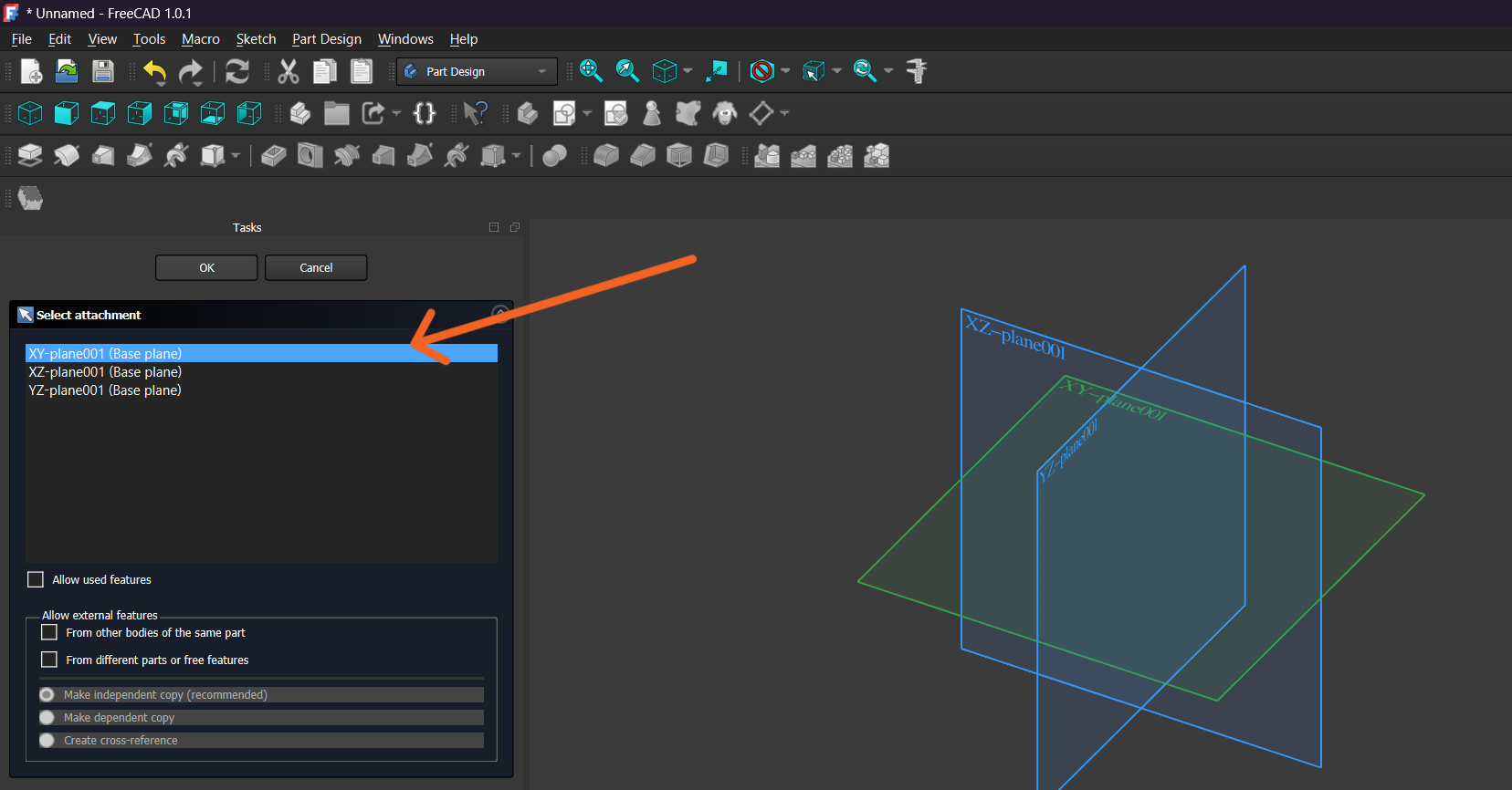
I created a new Sketch and selected the XY Plane as the reference plane for the drawing.
Using the previously defined parameters, I started drawing the geometry of the model.
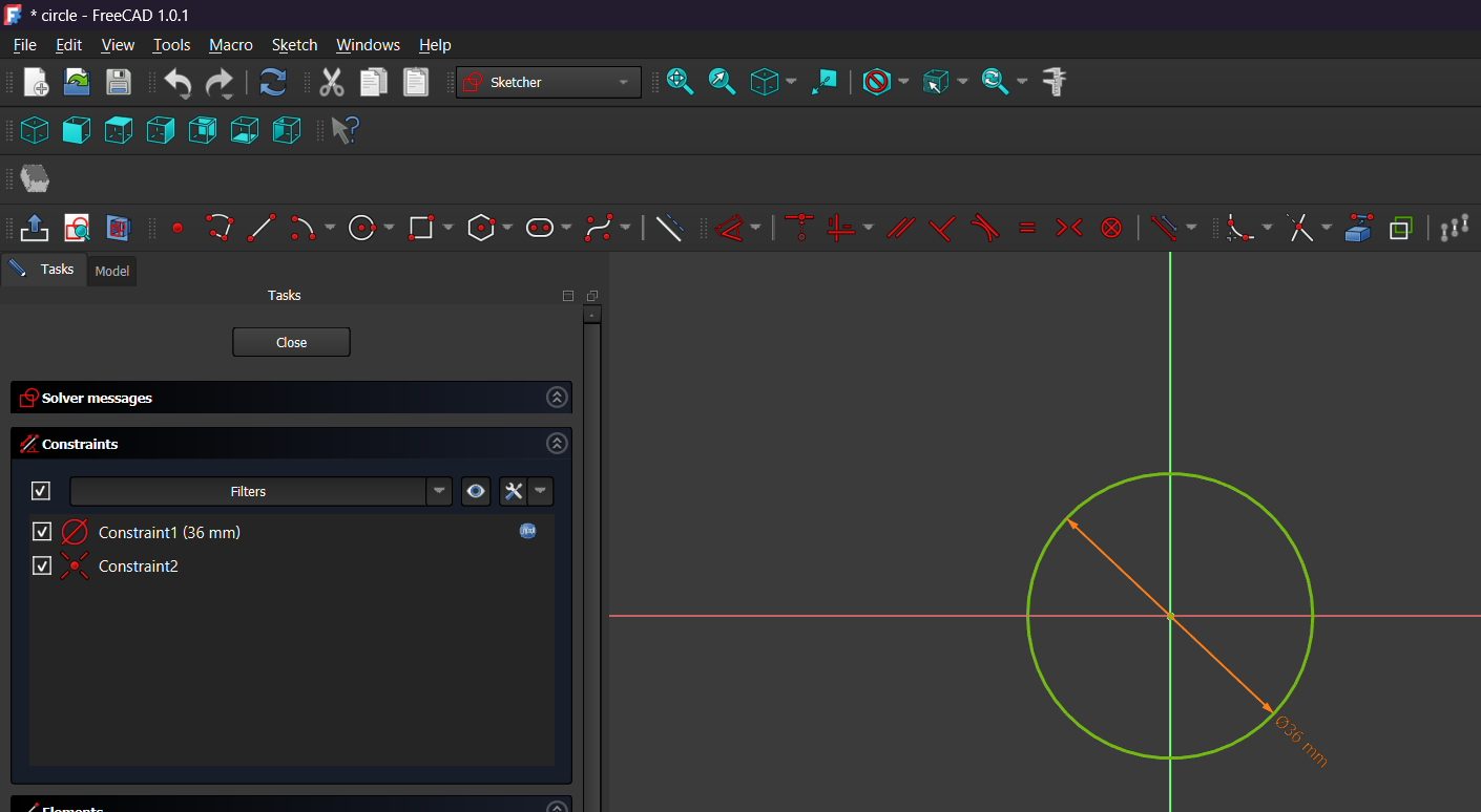
After creating the sketch, I applied a Diameter Constraint and set the circle diameter to 36 mm. The center of the circle was constrained to the origin, ensuring that the geometry remained fully defined and easy to modify through parameters.
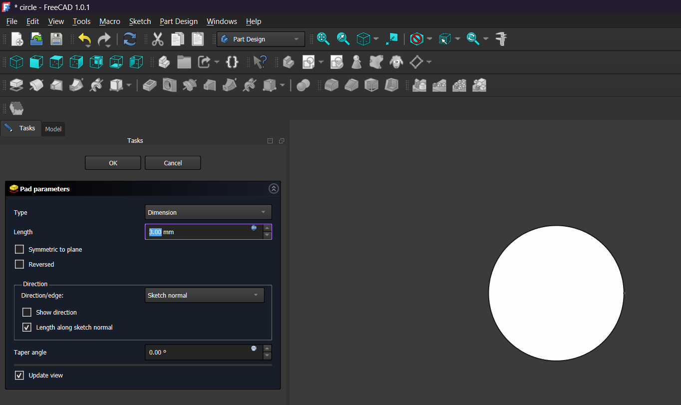
Next, I used the Pad tool in the Part Design workbench to convert the 2D sketch into a 3D solid. The pad length was set to 3 mm, corresponding to the plywood thickness defined in the spreadsheet.
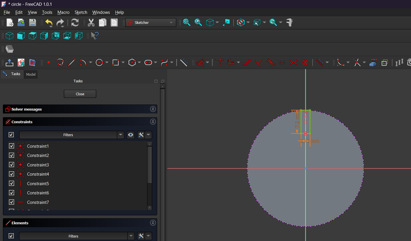
To create the connection slot, I sketched a small rectangular cut on the top edge of the circular part. Its dimensions were based on the previously defined joint parameters, allowing the slot size to be adjusted automatically by changing the spreadsheet values.
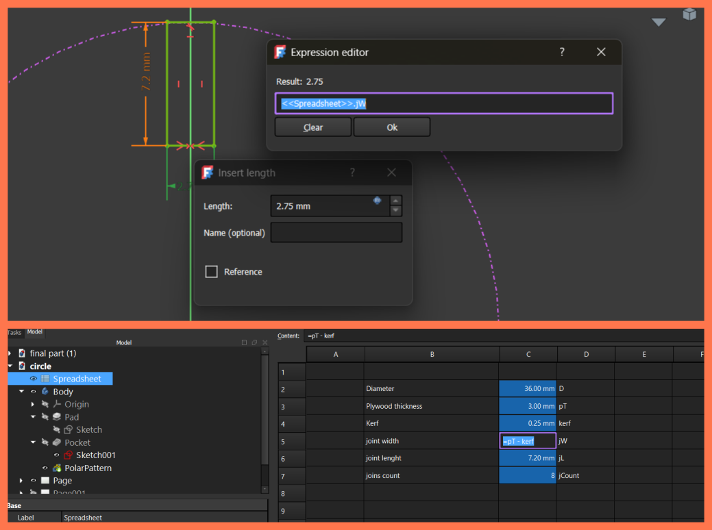
To account for the laser cutting kerf, I defined the joint width parameter (jW) in the FreeCAD Spreadsheet using the expression pT - kerf, where pT is the material thickness and kerf is the laser cutting compensation. In the slot sketch, I linked the width constraint to Spreadsheet.jW, so the slot width updates automatically whenever the material thickness or kerf value is changed.
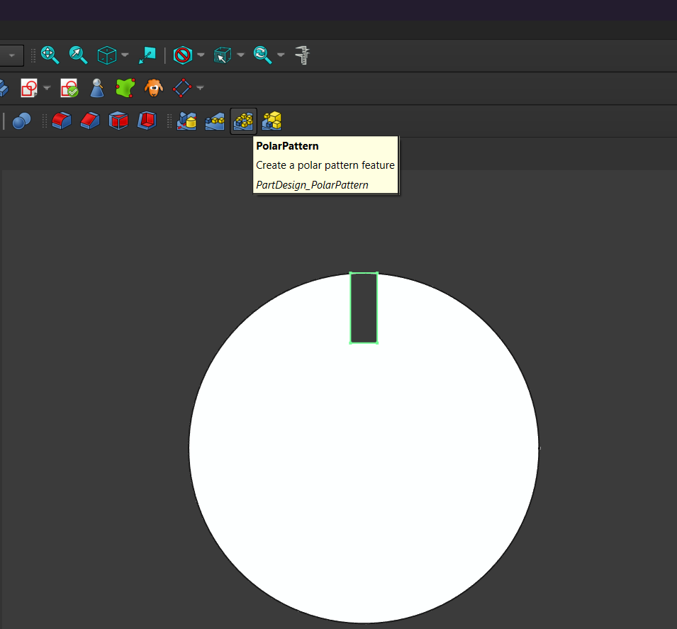
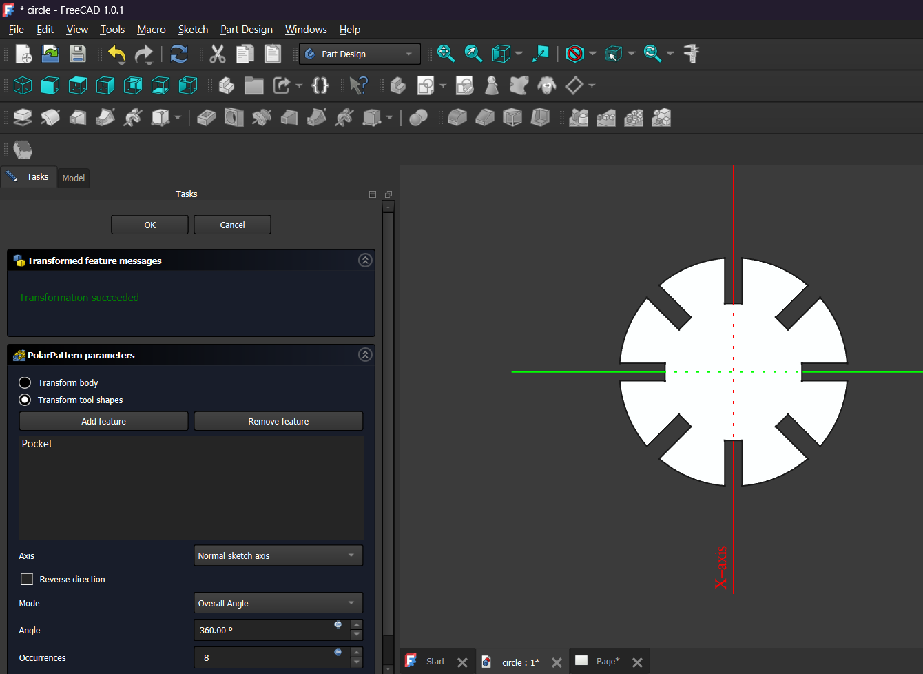
Finally, I used the Polar Pattern tool to duplicate the slot around the center of the circle. This feature evenly distributed the joints at equal angles, creating a symmetrical design while keeping the model fully parametric.
The result is a circular component with eight evenly spaced joints, ready to be exported for laser cutting. Since all critical dimensions are controlled from the spreadsheet, the model can be easily adapted to different material thicknesses or design requirements.
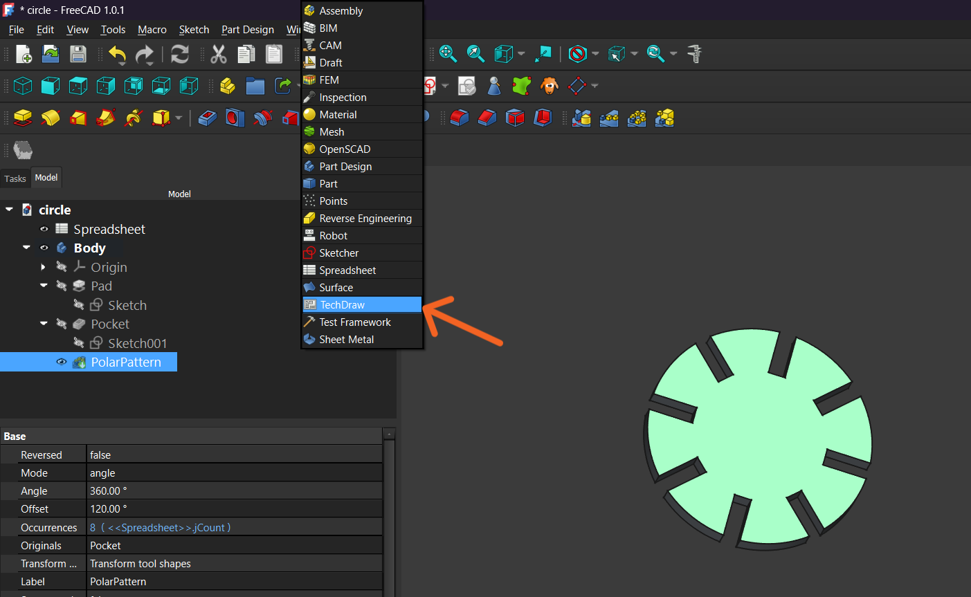
After creating the Polar Pattern, the model was completed and all joints were automatically distributed around the circle according to the parameters defined in the spreadsheet. This ensured that any modification to the number of joints, diameter, material thickness, or kerf value would automatically update the entire design, keeping the model fully parametric and easy to adapt for different fabrication requirements.
Once the 3D model was finalized, I switched to the TechDraw Workbench to create a technical drawing of the part. TechDraw allows generating precise 2D views directly from the 3D model while preserving all the dimensions and geometry.
I then created a new drawing page using the default template. This page serves as a workspace where different views of the model can be placed and arranged before exporting them.
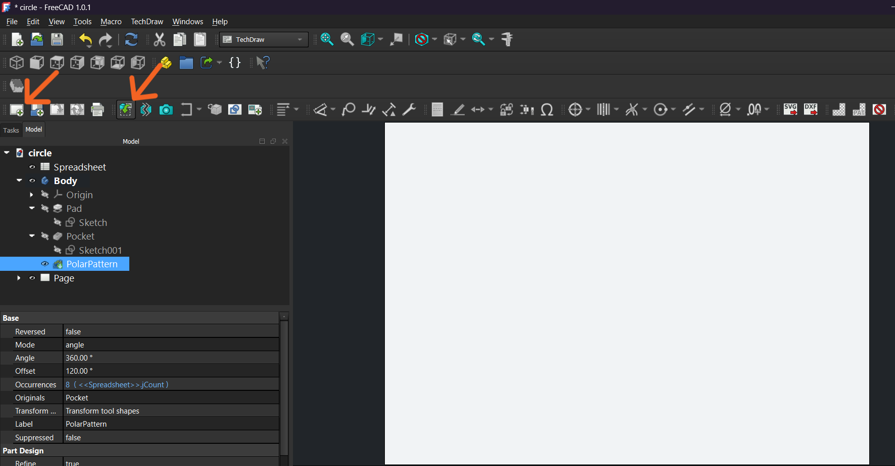
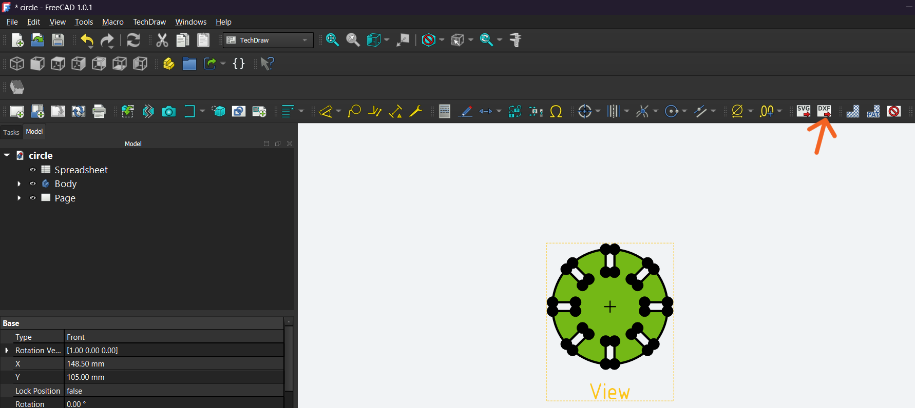
Next, I selected the model and inserted a Front View onto the drawing page. TechDraw automatically generated a 2D projection of the part, including all the slots created with the Polar Pattern.
Laser Cutting Process
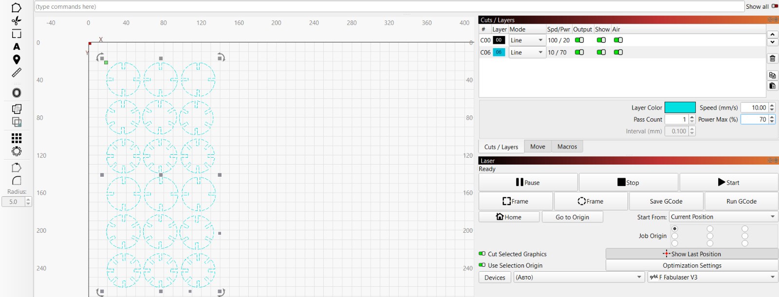
Finally, I exported the drawing as a DXF file. Then I moved to the LightBurn software and imported my files onto the work area. I arranged them on the workspace and set the appropriate cutting parameters, including speed and power, according to the material requirements.
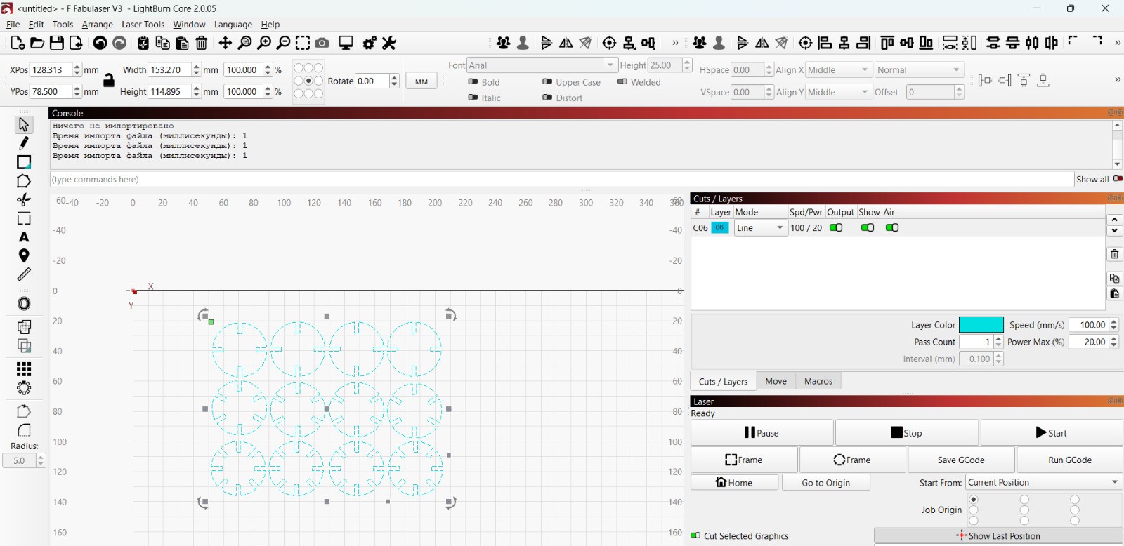
During the cutting process, I noticed that our laser machine showed some deviation. After a certain area of the work field, the laser beam started to split into two parts, which affected cutting accuracy and caused uneven results.
We checked the possible causes and tried to adjust the machine’s focus and optical system to minimize the issue. At the same time, we limited the working area to the section where the laser beam remained stable and properly focused.
After that, we rearranged the parts in LightBurn and performed a second cutting test. In this case, the cutting process worked normally without noticeable deviations.
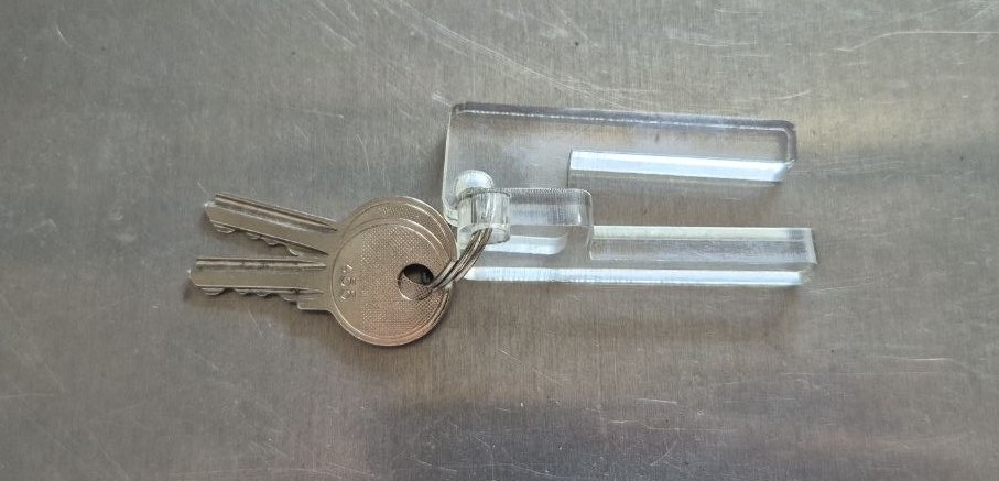
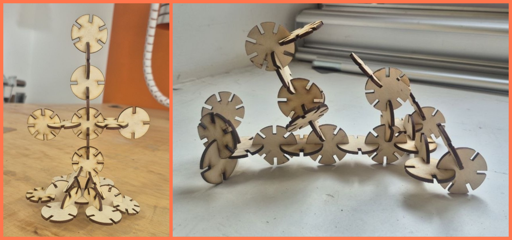
Assembly
After that, I assembled the cut parts, combining them to create different shapes and structural forms. During the assembly process, I also checked how accurately the joints fit together and how well the parts aligned, which helped evaluate the cutting quality and the overall result.
Conclusion
During this week, we learned how a CO₂ laser cutter works and how important correct settings are. Through the experiments, it became clear that cutting and engraving quality strongly depends on speed, power, and focus.
We also understood that even small changes in the parameters can significantly affect the final result. Overall, this week helped us better understand the machine’s operation and develop a more accurate approach to working with materials.
Files
Vinyl Cutter
Laser Cut