3.Computer-Controlled Cutting
This week I explored FreeCAD and LightBurn to understand the workflow of computer-controlled cutting.
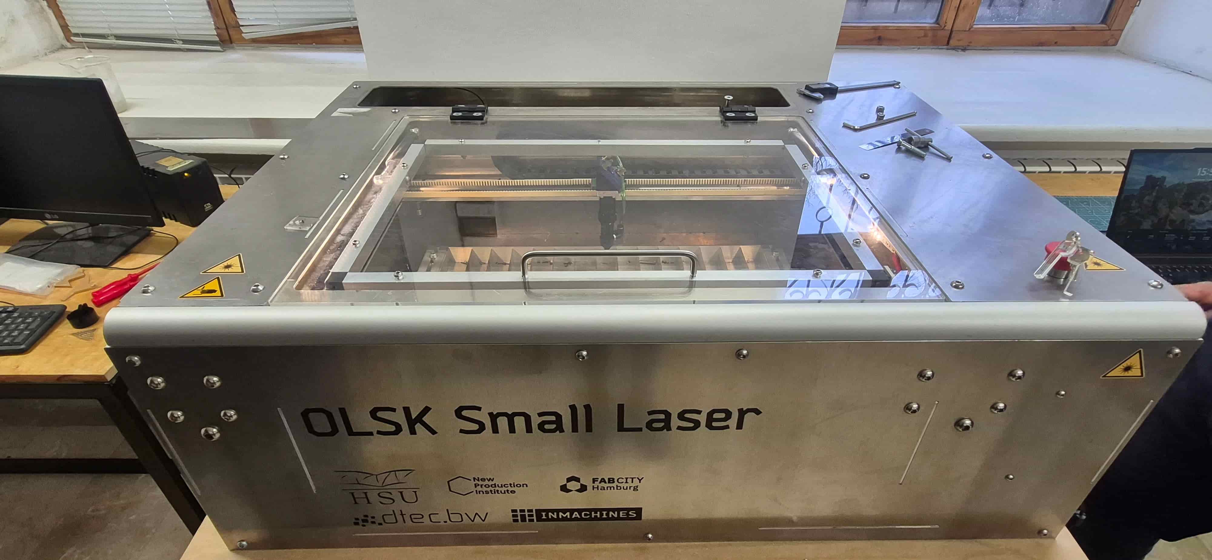
I also learned how to prepare and configure the laser cutting machine before fabrication. The machine used in the Gyumri lab is the OLSK Small Laser V1, an open source CO2 laser cutter designed by InMachines Ingrassia GmbH, part of the Open Lab Starter Kit family.
Group Assignment
This week, I worked together with Ani as part of the group assignment.
At the beginning, we explored the laser cutting machine, focusing on its structure and safety rules before starting any practical work.
Machine Specifications
The laser cutter used in this week’s work is a CO2 laser system with the following technical specifications:
| Parameter | Value |
|---|---|
| Laser source | 40W CO2 |
| Cutting area | 600 × 400 mm |
| Resolution | 0.05 mm |
| Max cutting thickness (acrylic) | 10 mm |
| Max cutting thickness (MDF) | 6 mm |
| Max cutting thickness (plywood) | 8 mm |
| Max speed | 1000 mm/s |
| Motion system | Linear rails and linear shafts |
| Frame and housing | Interlocked aluminum plates |
| Bed | Aluminum lamella |
| Sensors | Inductive probes |
| Controller | 32-bit Teensy 4.1 |
| Firmware | GRBL-HAL |
| Machine dimensions | 1161 × 812 × 390 mm |
The 40W CO2 laser source is well suited for cutting and engraving non-metallic materials such as wood, acrylic, and cardboard. The GRBL-HAL firmware running on a 32-bit Teensy 4.1 controller provides precise motion control, while inductive probes allow reliable bed sensing.
Safety Rules for Laser Cutting
Before and during every laser cutting session, the following safety rules must be followed.
Never leave the machine unattended while it is running. Fire can start quickly, especially when cutting wood or cardboard. Always stay present and keep a fire extinguisher nearby.
Always use ventilation. The laser produces fumes and fine particles when cutting or engraving materials. The exhaust system must be running before starting any job.
Never cut PVC or vinyl with a CO2 laser. These materials release chlorine gas when burned, which is toxic and also damages the machine’s optics and metal parts.
Wear appropriate eye protection. CO2 laser wavelength (10.6 µm) is invisible, but reflections and secondary radiation can still cause eye damage. Use laser-rated safety glasses.
Keep the lid closed during operation. The enclosure protects from stray beam reflections. Do not open the lid while the laser is active.
Check the material before cutting. Unknown or composite materials may contain coatings or adhesives that produce harmful gases. When in doubt, do not cut.
Keep the lens and mirrors clean. Dirty optics absorb energy, overheat, and can crack or cause misfires. Clean only with appropriate lens tissue and approved solutions.
Know how to stop the machine. Locate the emergency stop before starting. In case of fire or malfunction, stop the machine immediately and do not panic.
Do not exceed the maximum material thickness. Cutting too-thick material causes the beam to scatter inside the cut, producing more heat, charring, and inconsistent results.
These rules were followed throughout our work this week. Safety awareness is as important as technical skill in a fabrication environment.
To understand how accurately the machine works, we checked the laser beam position using a transparent acrylic sheet. This helped us clearly see where the beam hits without creating smoke.
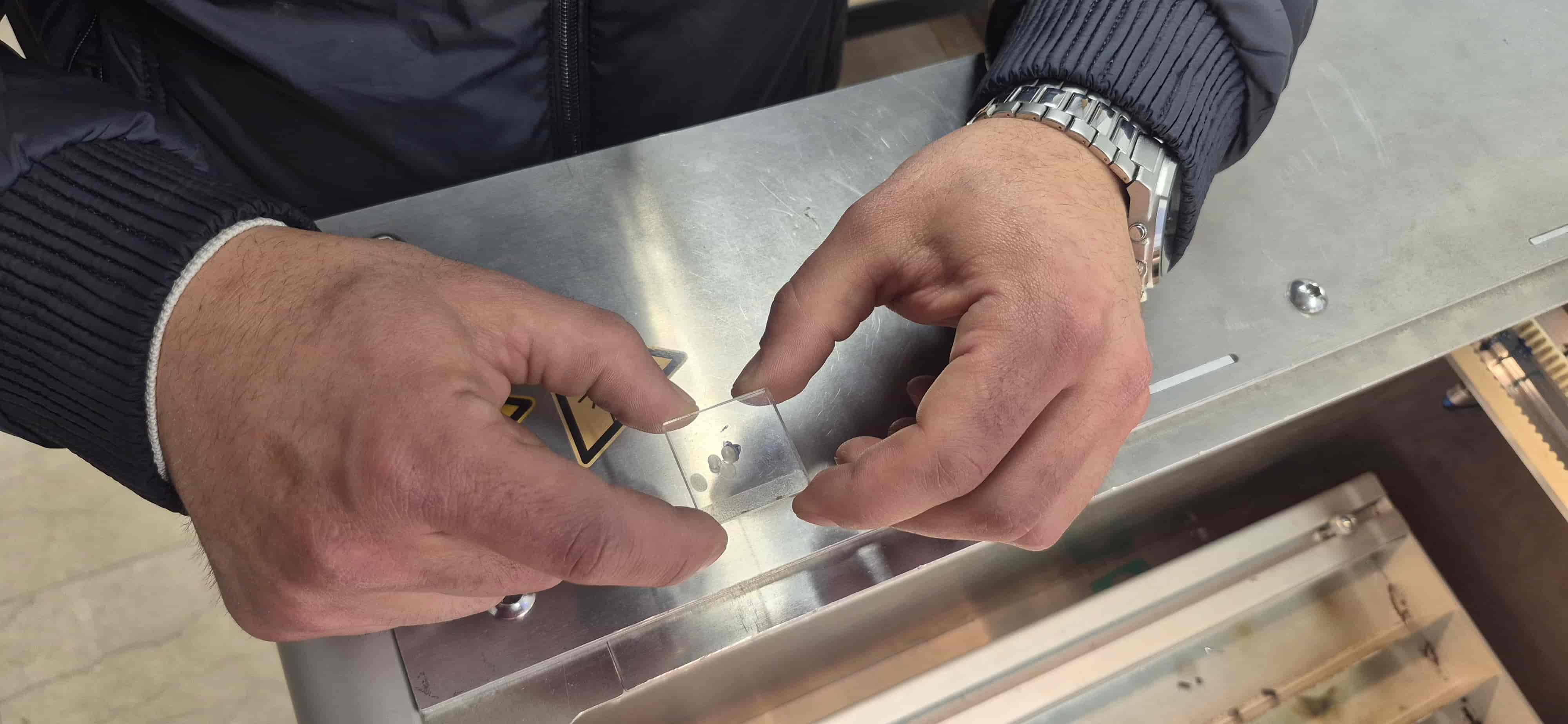
We avoided using paper because it could burn and produce smoke that might damage the mirrors.
After observing the marks, we analyzed how the beam behaves across different positions.
Mirror Adjustment
Next, we adjusted the mirrors of the laser system.
During this laser setup process, our work was supported by Aram Pijikyan, a lecturer at the State Academy of Fine Arts of Armenia, who guided us and explained in detail the fundamentals of the laser cutting machine.
By carefully tuning the alignment screws, we ensured that the laser beam travels through the center of the optical path and reaches the working head correctly.
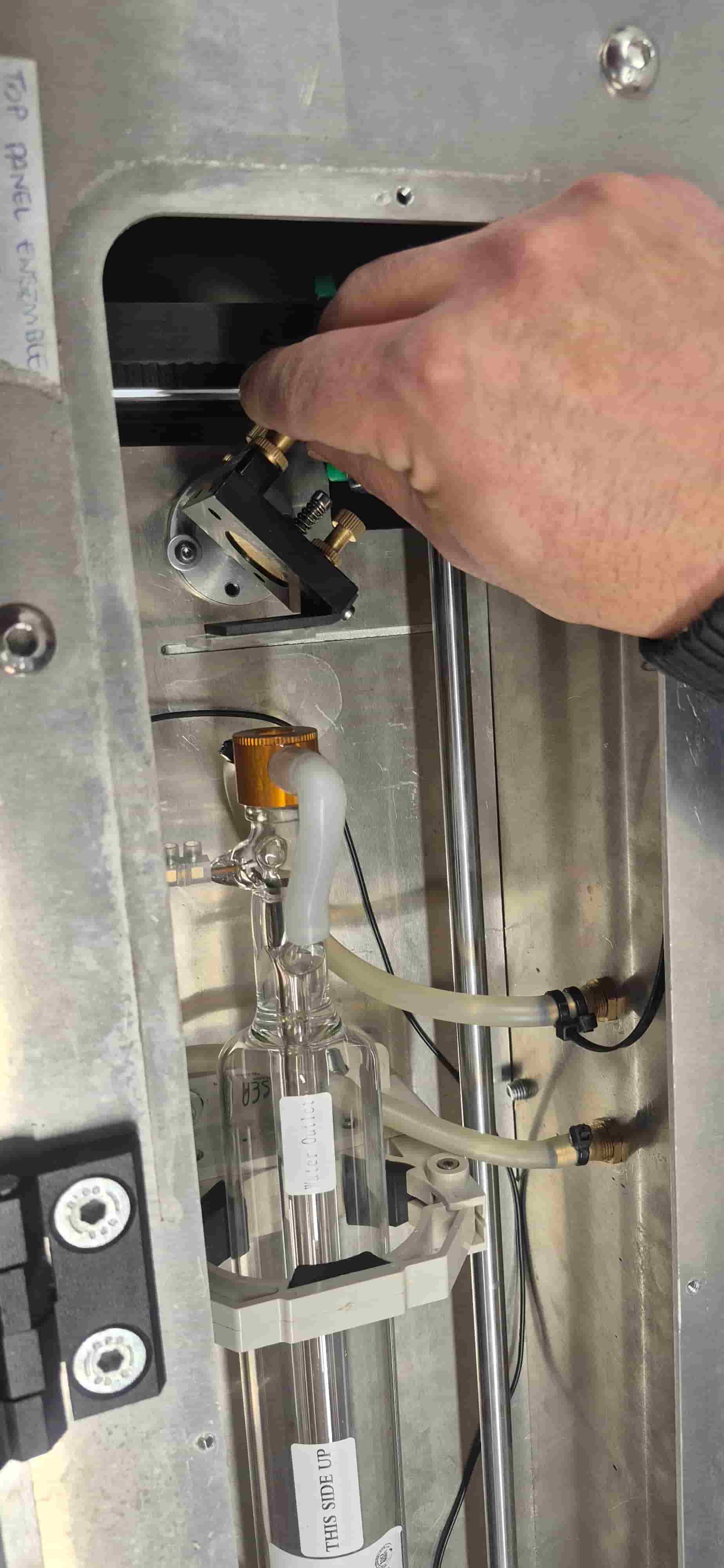
We repeated this process several times until the beam consistently hit the correct positions.
This step was important to make sure the machine is properly calibrated and ready for accurate cutting.
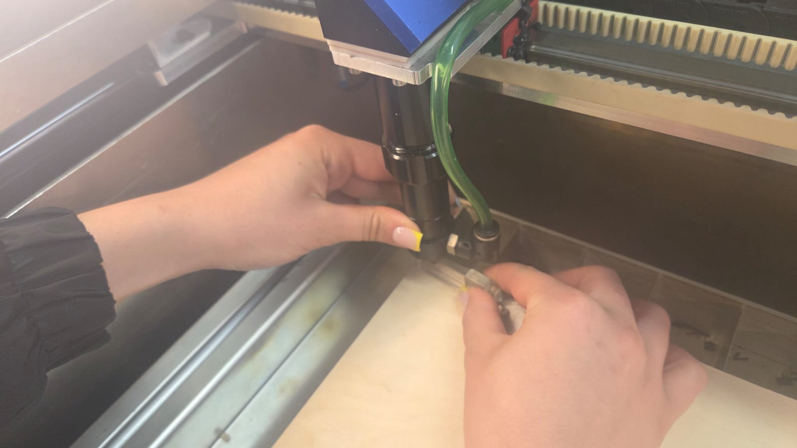
Focus Adjustment
Before cutting anything, the laser also needs to be properly focused on the material surface, otherwise the cut quality suffers even if the beam alignment and mirrors are correct.
The lens in our machine has a fixed focal length of 50.8 mm (2 inches), so the distance between the nozzle and the material has to match that. To set it, we used a small calibration tool, 6 mm in height. We placed it flat on top of the material and slowly lowered the laser head until it just touched the top of the tool — that position became our reference focus height for the material being used.
Axis Calibration Issue
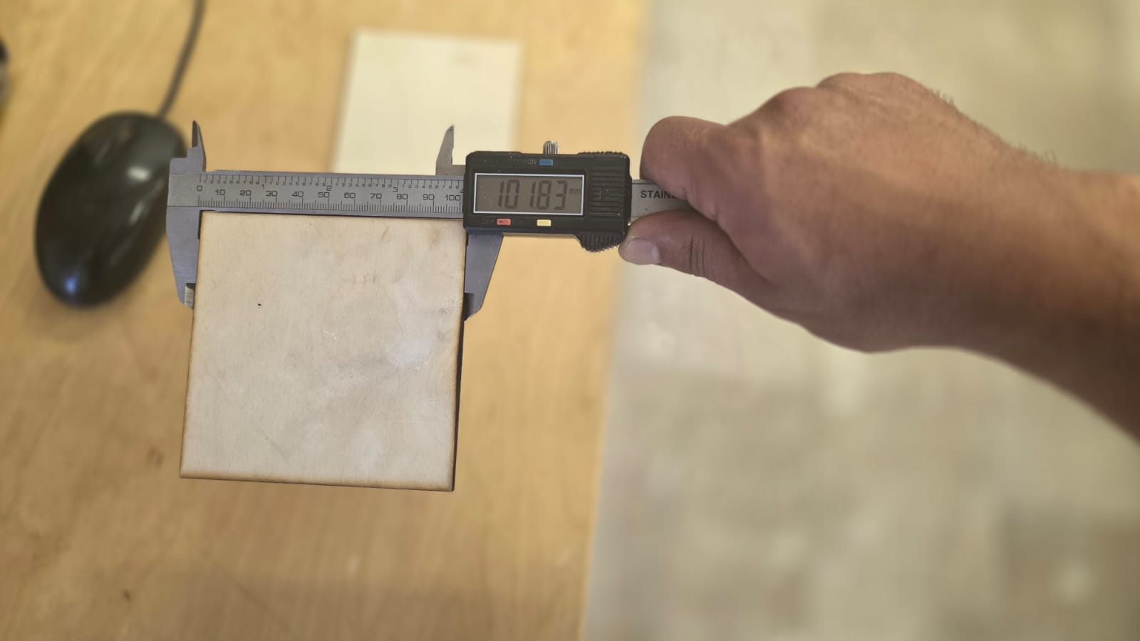
During the laser kerf test, something didn’t add up: the cut parts measured larger than the design size, when they should have come out smaller, since the kerf always removes a bit of material from the part. That pointed to something off with the machine’s X/Y axis scaling, not just kerf.
To check this, we cut a 100 mm test square and measured it. Along X, it came out at 101.83 mm:
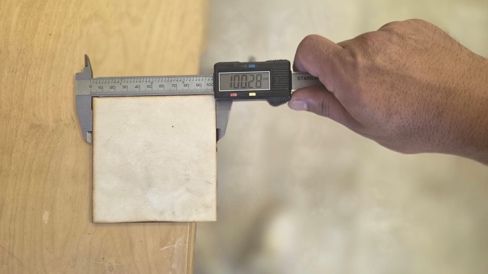
and along Y, 100.28 mm:
Temporary Adjustment
There’s a known effect on the laser in the Dilijan lab: a cut part typically comes out about 0.15 mm smaller than its drawn size, so a 100 mm square should normally measure around 99.85 mm.
Taking that 0.15 mm shrinkage into account, the actual distance the axes had moved during our test cut was:
- X: 101.83 + 0.15 = 101.98 mm
- Y: 100.28 + 0.15 = 100.43 mm
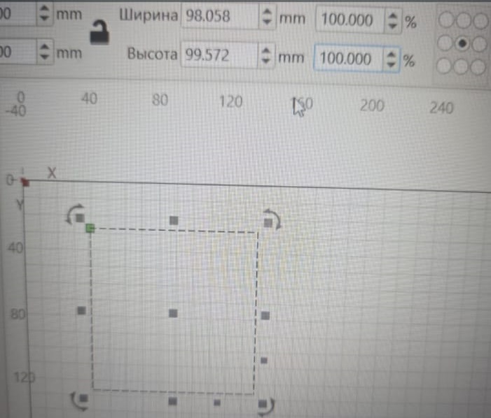
So if we wanted the axes to actually move exactly 100 mm, the drawn length had to be scaled down accordingly:
- X: (100 / 101.98) × 100 = 98.058 mm
- Y: (100 / 100.43) × 100 = 99.572 mm
In other words, 98.058% on X and 99.572% on Y. We entered these percentages into the object’s width and height fields in LightBurn as a quick fix.
After cutting again with this correction, we measured 99.80 mm along X:
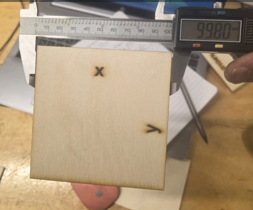
and 99.74 mm along Y:
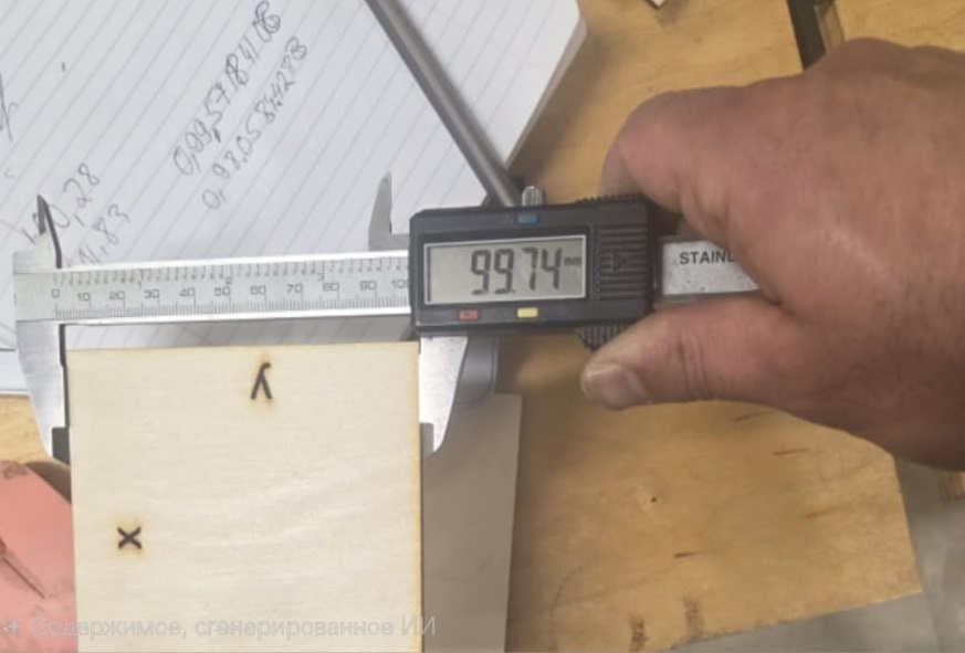
This got us close to the correct size, but it was only a band-aid — we would have had to re-apply the same scaling on every single file from then on, instead of solving the actual problem.
Final Calibration
The real fix came from Aram Pichikyan, who went into the machine’s GRBL configuration and corrected how the axis movement was set up — making sure the stepper motors’ steps actually matched the real distance traveled. Unlike the LightBurn workaround, this fixed the issue at the machine level itself, so there was no need to scale anything per file afterward. From this point on, the machine’s movement was accurate again.
Engraving and Cutting Tests
Once the machine was properly calibrated, we ran test samples to find good cutting and engraving settings for two materials: 3 mm plywood and 2.7 mm acrylic.
Cutting Tests
For plywood, we kept the power at a fixed 70% and only changed the speed — the idea was to find the slowest speed that still cuts through cleanly, instead of just maxing out the power.
At 70% power and 10 mm/s, the plywood cut through completely. At 20 mm/s, the same power wasn’t enough anymore. Since these two speeds are a factor of two apart, the actual cutoff point between “cuts” and “doesn’t cut” is somewhere in between — a more detailed test with smaller speed steps would be needed to pin it down exactly.
For acrylic, we changed both speed and power together in this test, which makes it harder to read the cut quality cleanly. Still, we found a setting that worked: 95% power at 10 mm/s cut cleanly through the 2.7 mm acrylic.
](../../images/week03/cutting-2.jpeg)
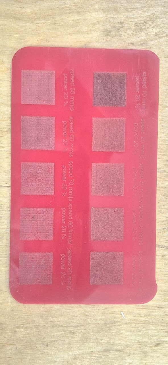
Engraving Tests
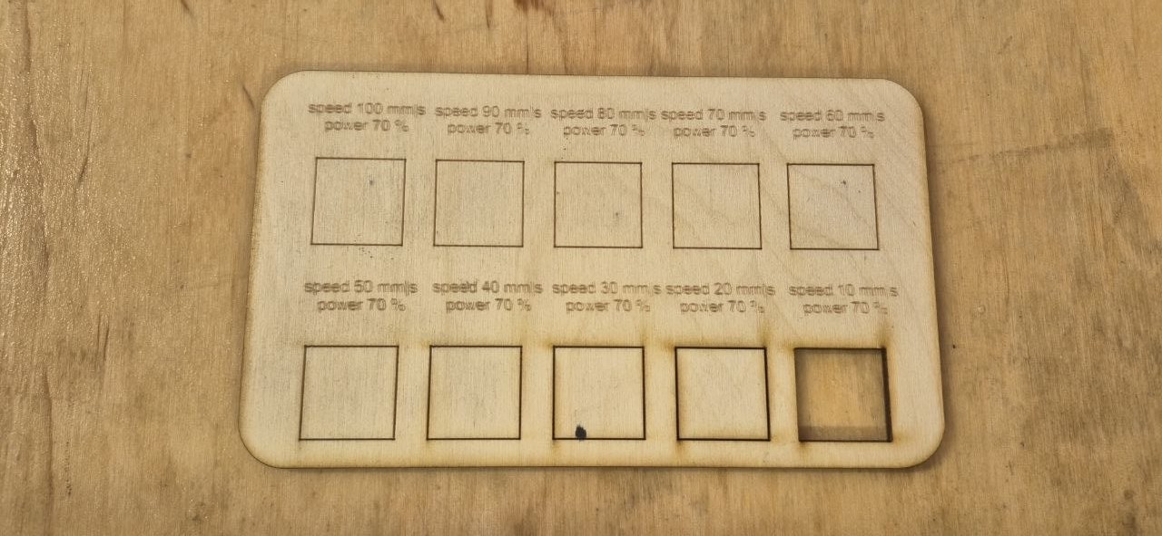
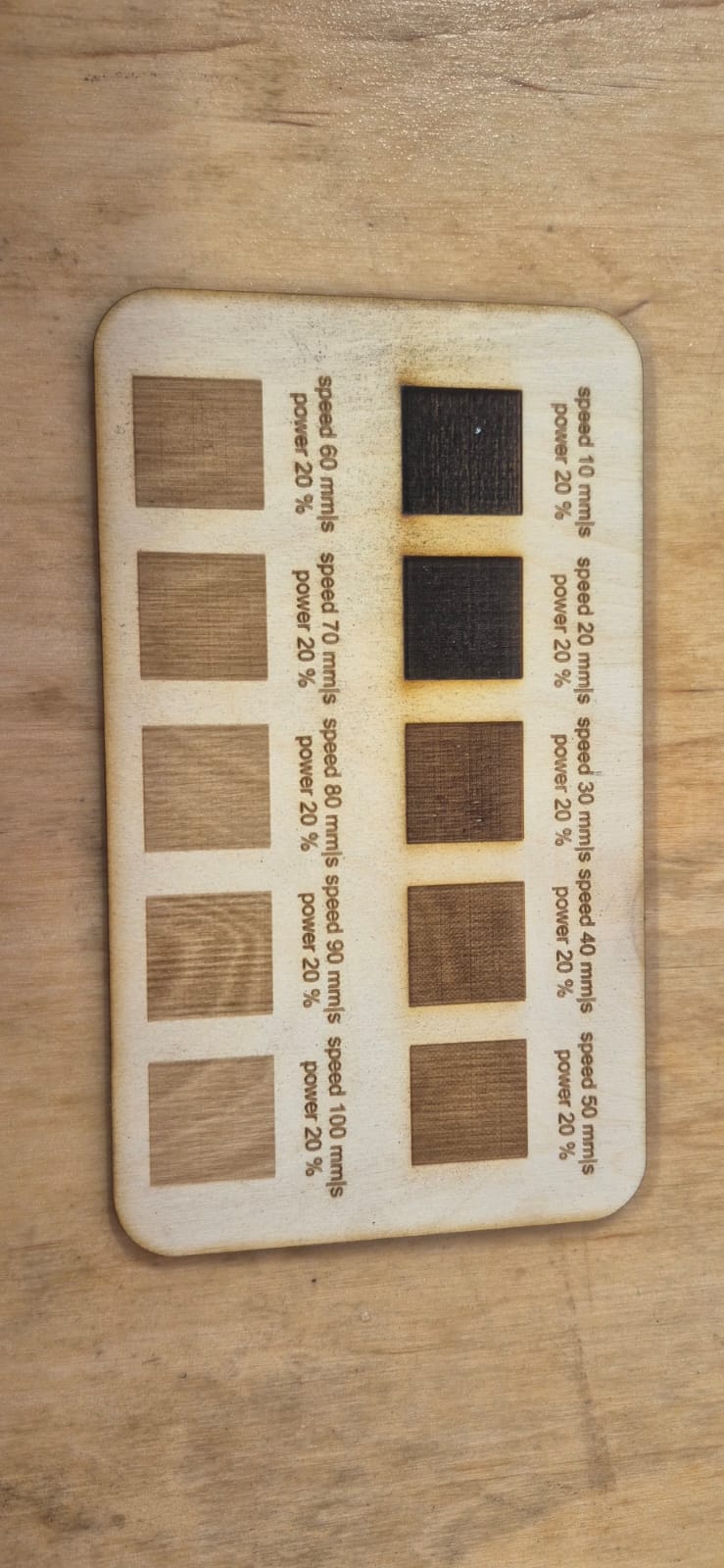
For engraving, the power stayed fixed at 20% for both materials, and only the speed changed.
On plywood, we ran the test at 10, 20, 30, 40, 50, 60, 70, 80, 90, and 100 mm/s. At 10 mm/s and 20 mm/s, the squares came out visibly scorched and dark — the laser was dwelling too long at that power and burning the surface instead of just marking it.
On acrylic, we tested 10, 20, 30, 40, 50, 55, 60, 70, 80, and 90 mm/s. Only at 10 mm/s did the surface darken noticeably; everything faster stayed within the normal frosted-engraving look without burning.
Kerf Measurement
Once the axis issue was fixed, we ran a kerf test with a calibration pattern of 11 rectangles (10 mm each), all cut as one continuous shape.
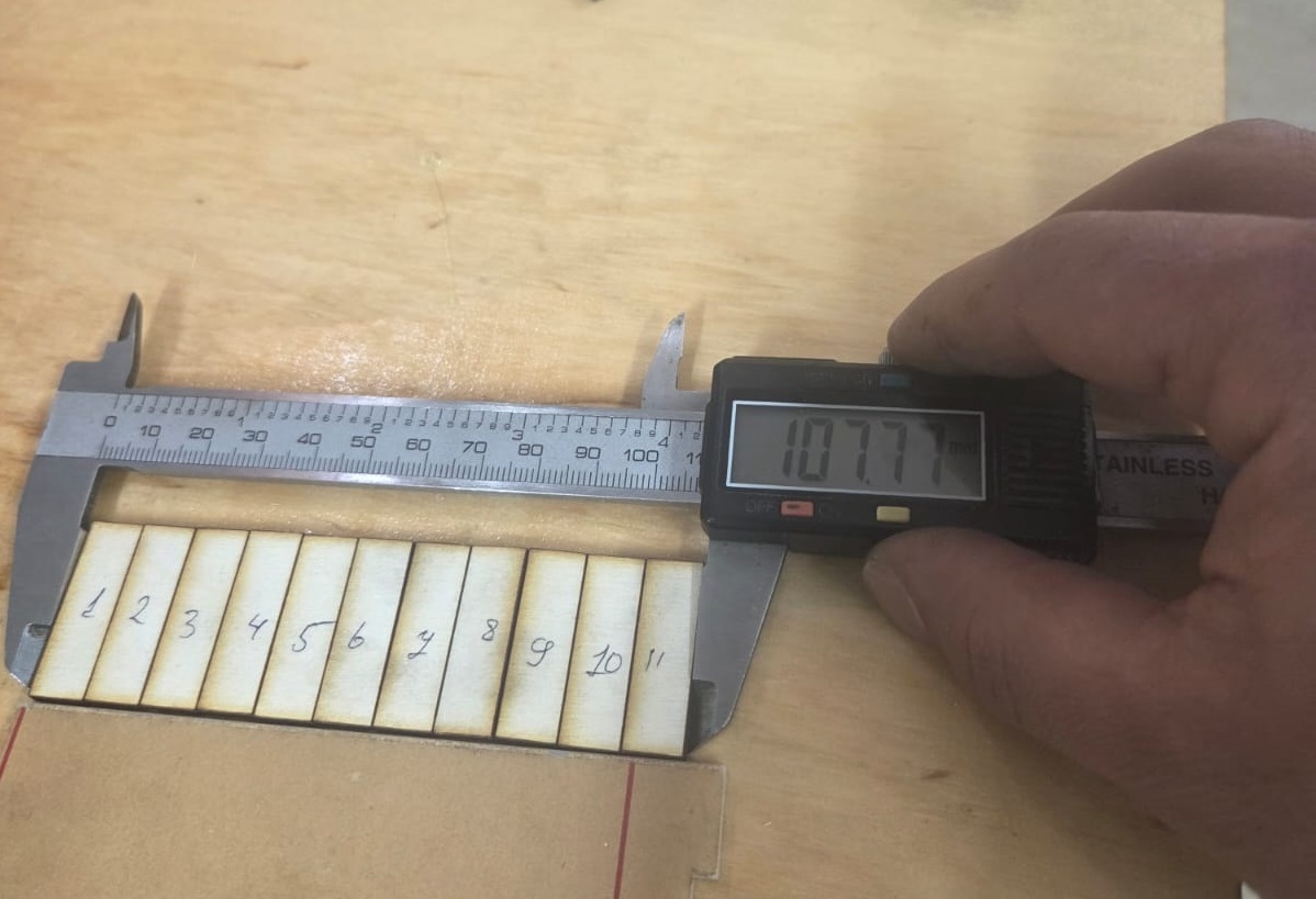
Expected total length: 110 mm Measured total length: 107.77 mm
With 11 rectangles, there are 10 cuts between them, plus half a kerf width lost on each of the two outer edges — so 11 effective kerf widths in total:
$$\text{Kerf} = \frac{110 - 107.77}{10 + 2 \times 0.5} = \frac{2.23}{11} \approx 0.20 \text{ mm}$$
We used this 0.20 mm kerf value for the parametric joint calculations afterward.
Vinyl Cutting — Individual Assignment
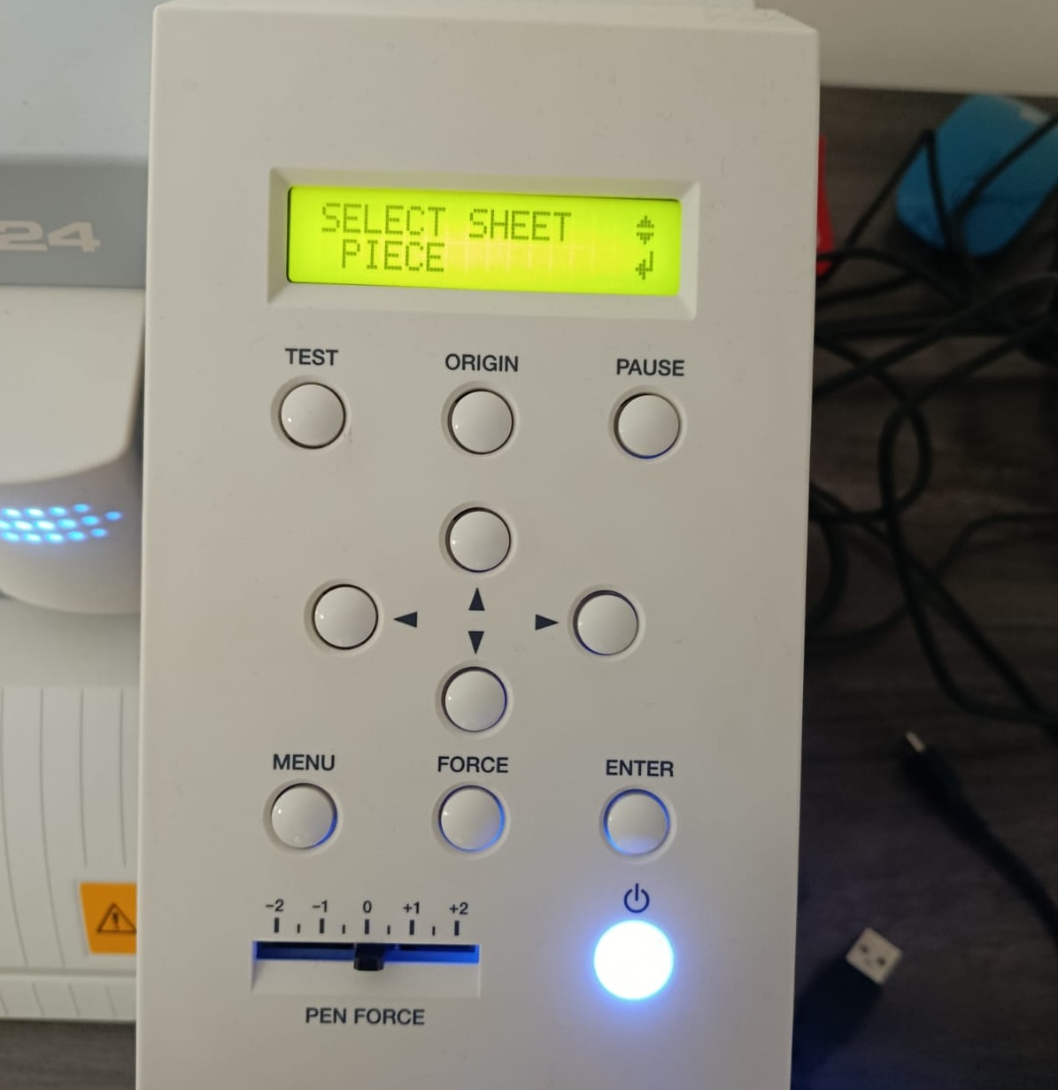
For the individual assignment, I worked with a vinyl cutter. The material loading method I used was Roll piece, where the vinyl roll is fed directly through the machine. Other available methods are Edge and Piece, but Roll piece suited my workflow for this task.
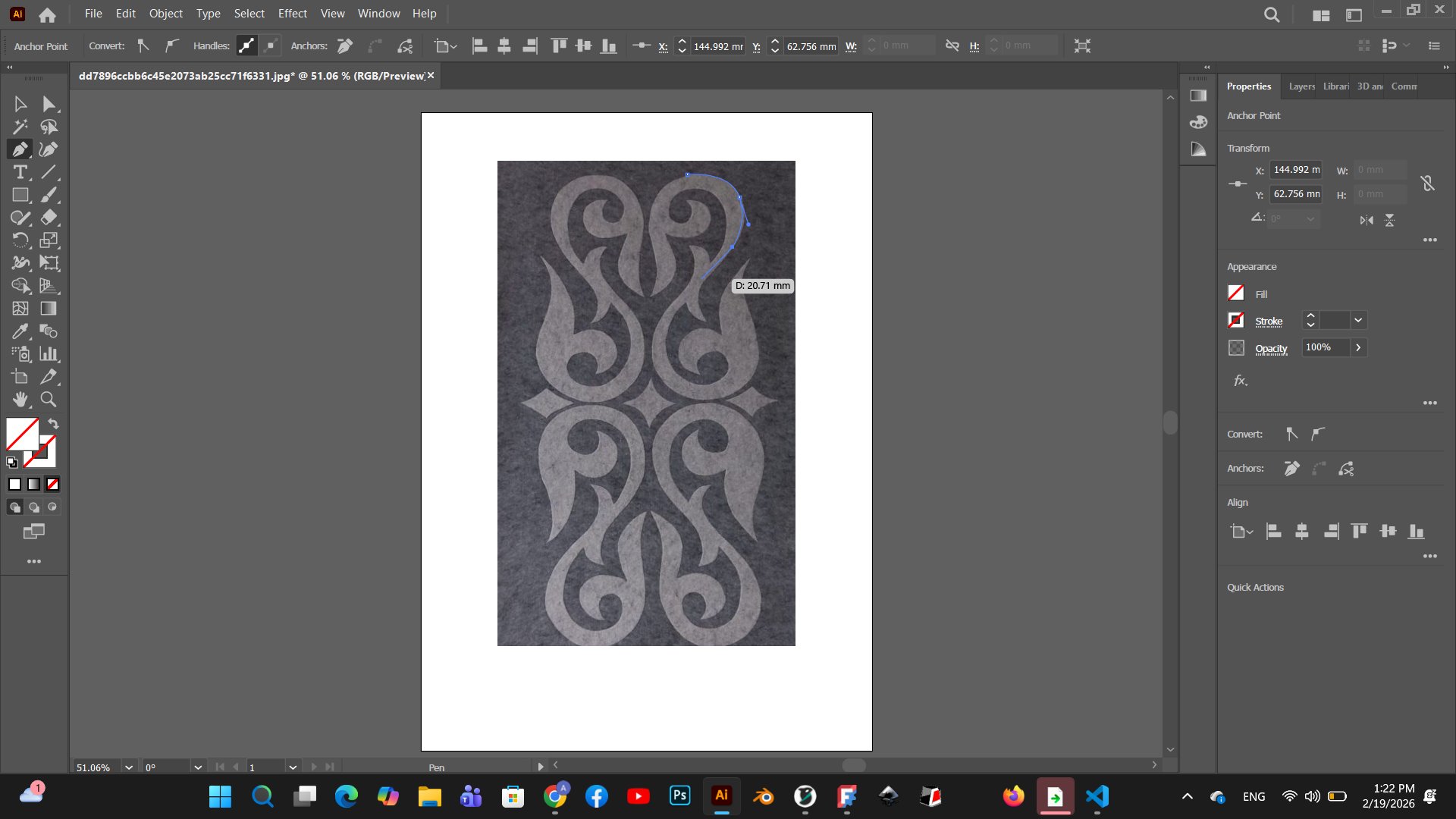
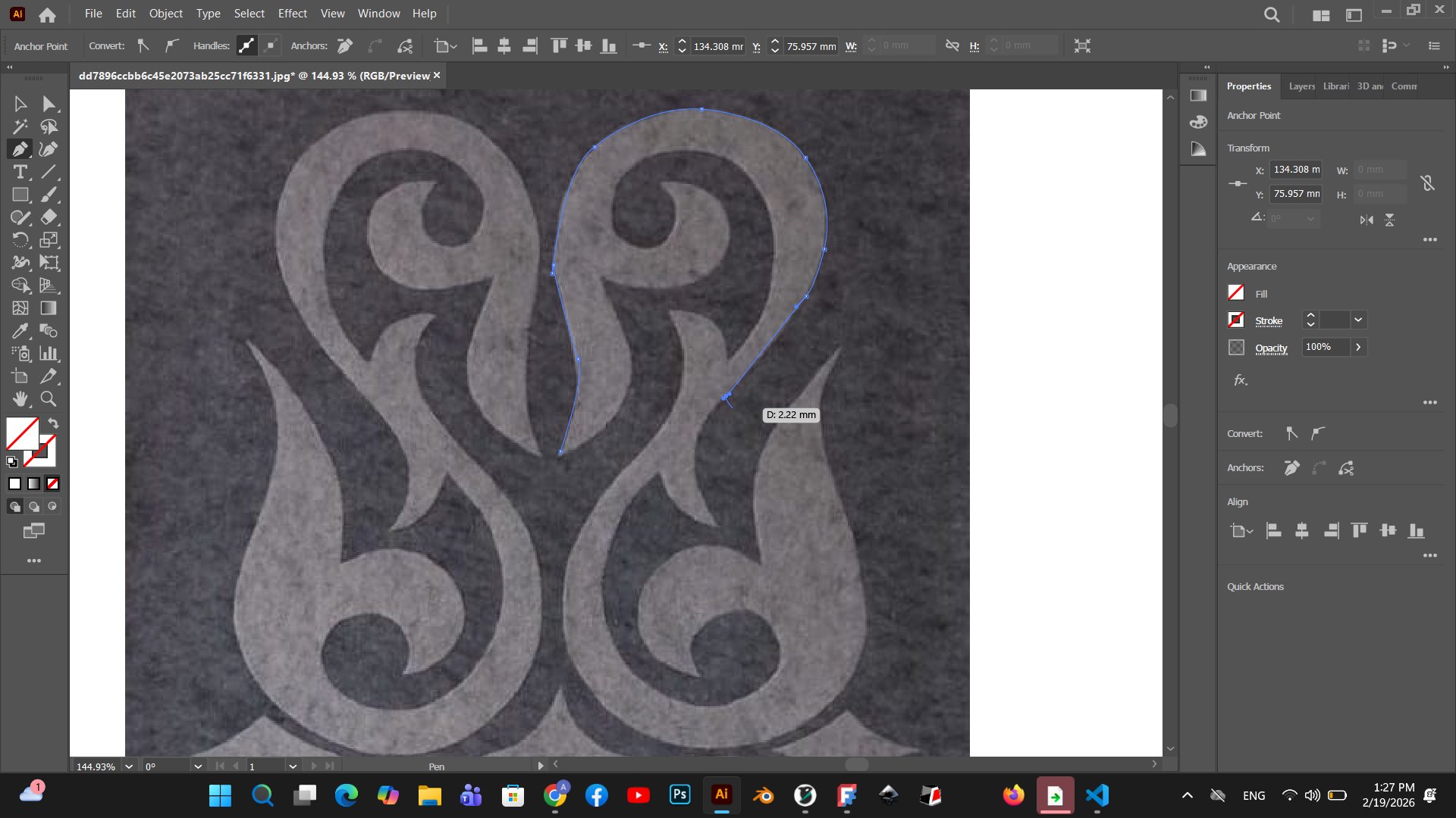
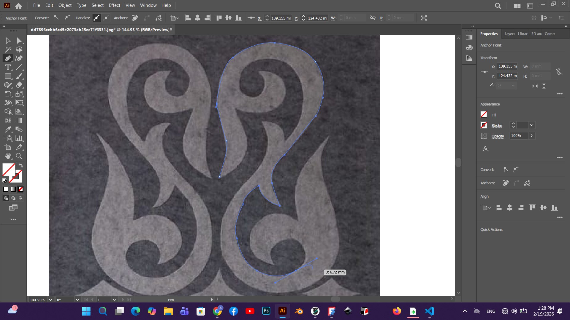
Design Preparation in Adobe Illustrator
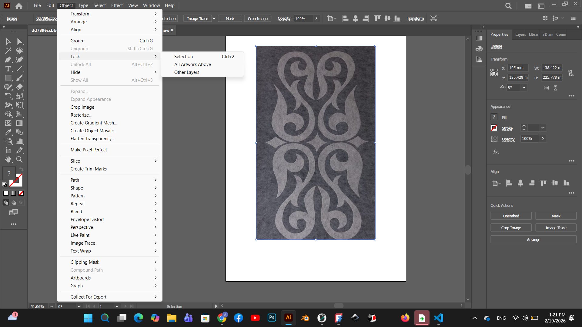
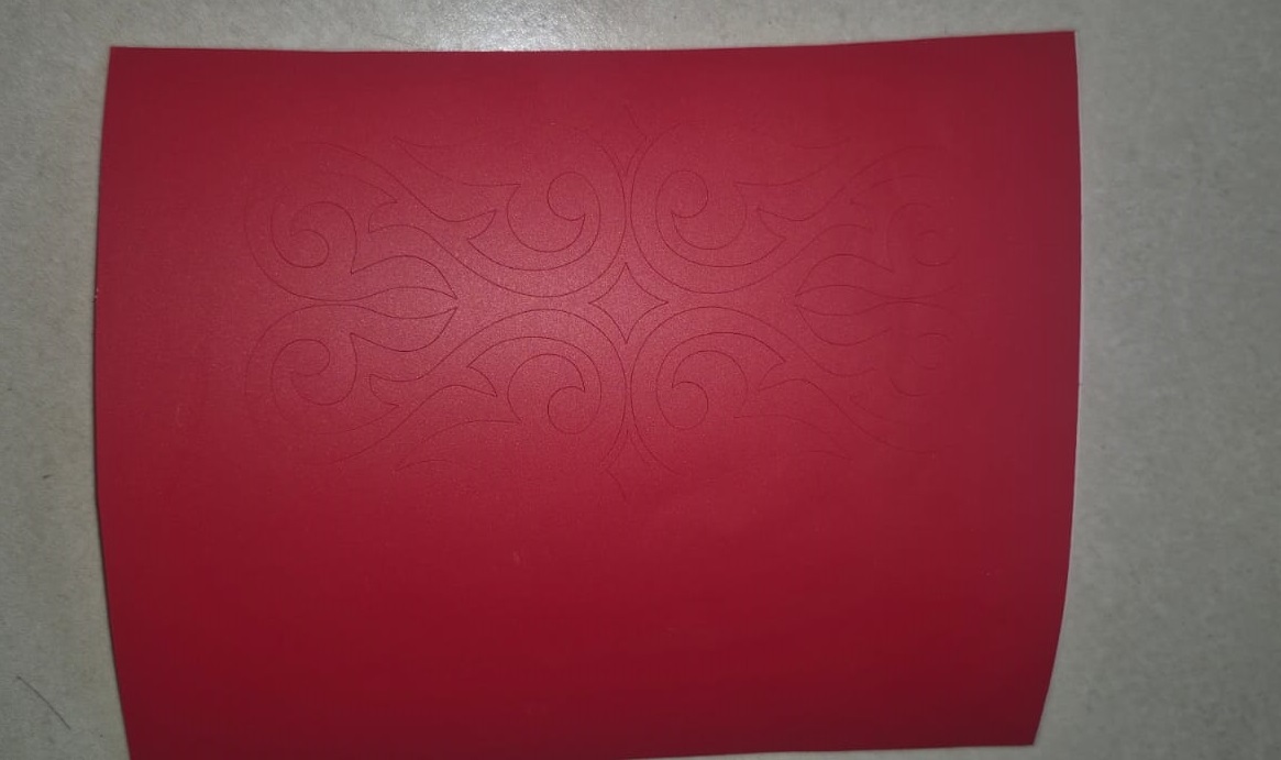
The ornamental pattern was first prepared in Adobe Illustrator. I used the Pen tool to trace the design over a reference image, placing anchor points carefully to follow the curves of the ornament.
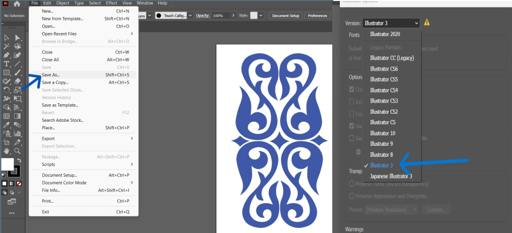
After tracing, I cleaned up the paths and prepared the file for export. To send the file to the Roland vinyl cutter, I saved it from Adobe Illustrator using File → Save As, selecting Illustrator 3 as the version — this legacy format is required for compatibility with the Roland software.
Blade and Machine Setup
The vinyl cutter used in this assignment is the Roland VersaSTUDIO GS2-24, a desktop vinyl cutting plotter with a 24-inch (610 mm) cutting width, designed for sign-making, sticker production, and detail cutting work.
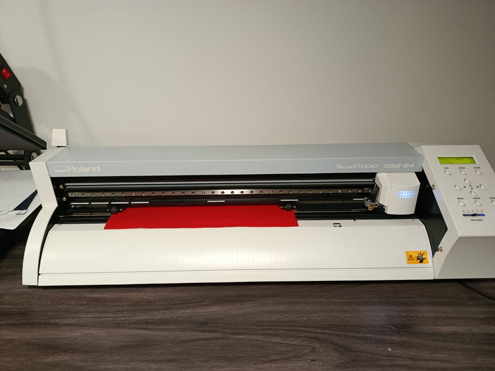
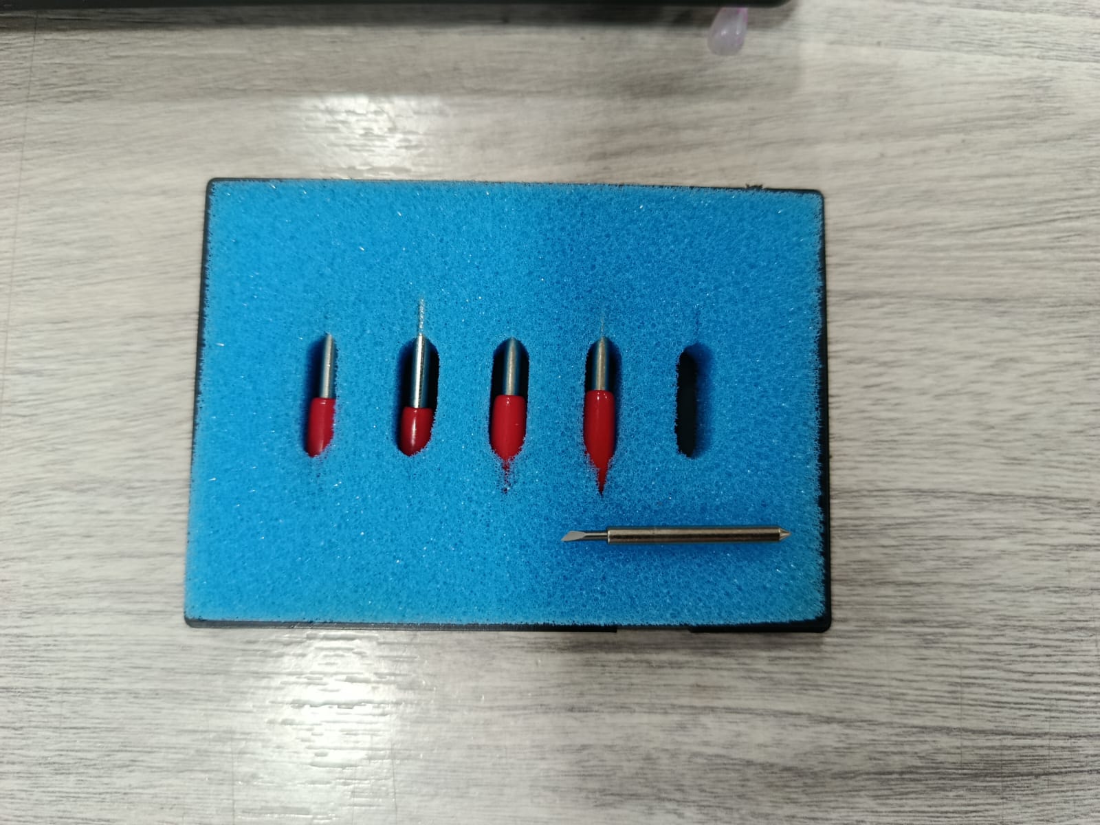
The vinyl cutter uses small interchangeable blades. Before starting, I selected the appropriate blade for the vinyl thickness.
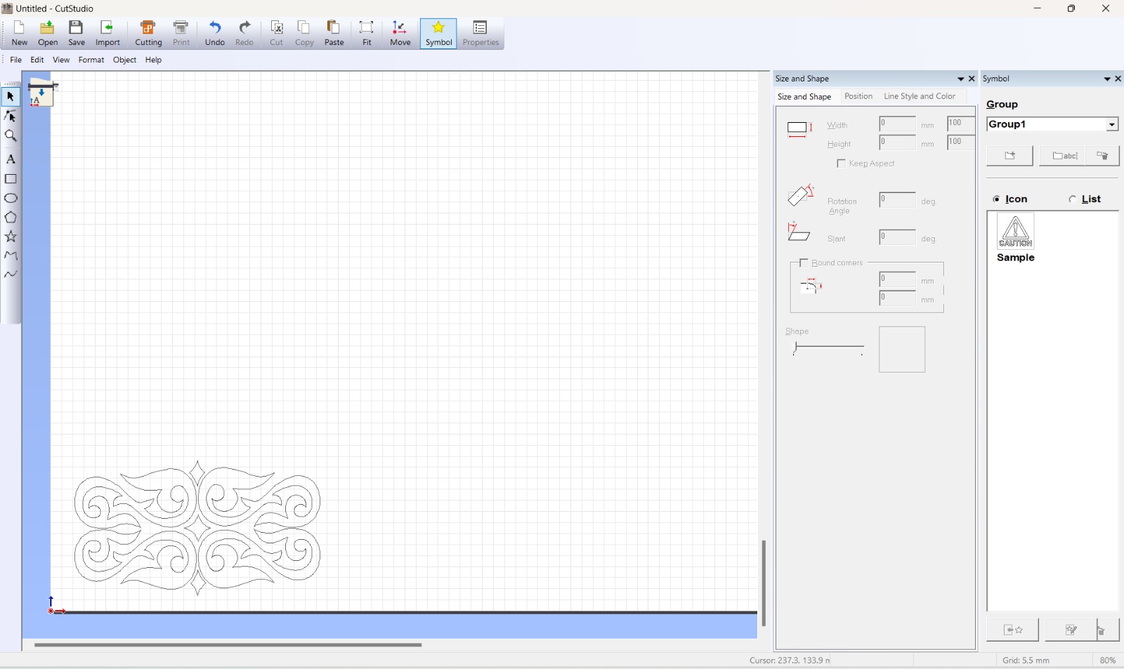
Importing the Design into CutStudio
I imported the traced ornament into CutStudio, the Roland software used to prepare and send files to the vinyl cutter.
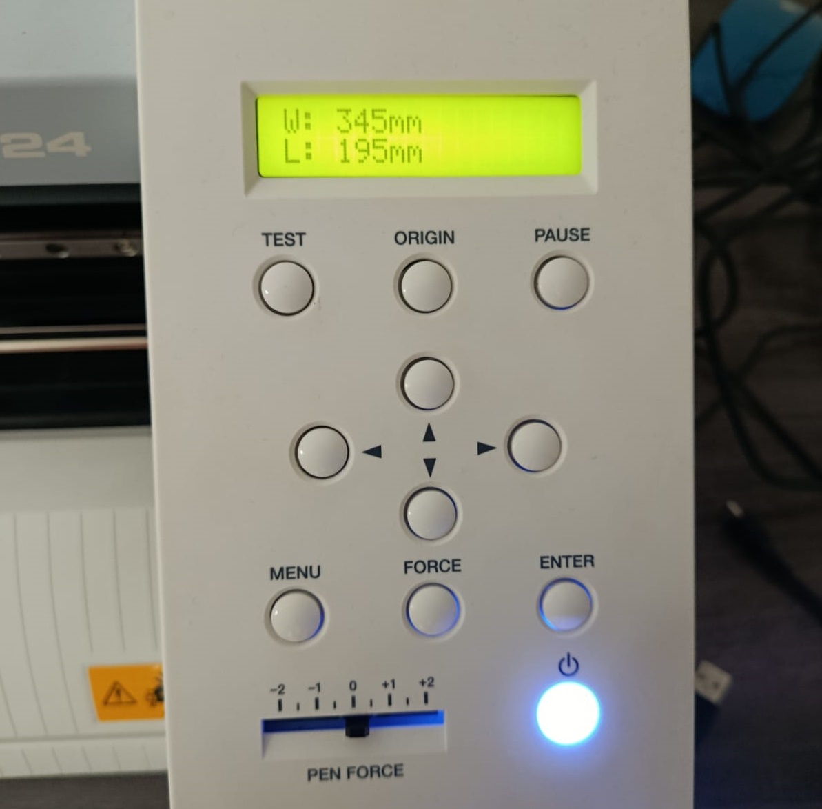
I then loaded the vinyl into the machine. On the control panel, I selected Piece as the sheet type and confirmed the material dimensions — the machine detected W: 345 mm / L: 195 mm.
Setting Cutting Parameters
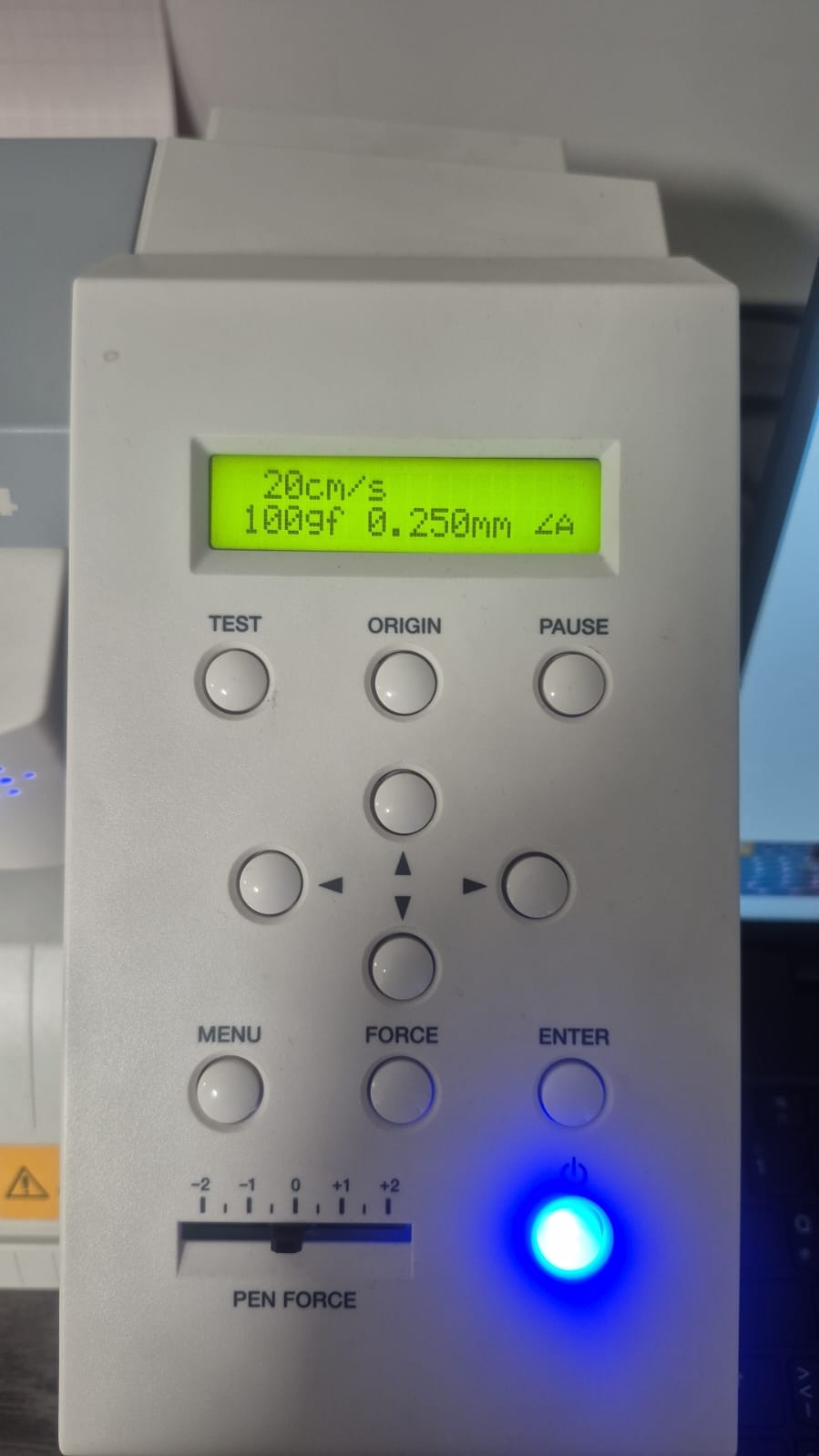
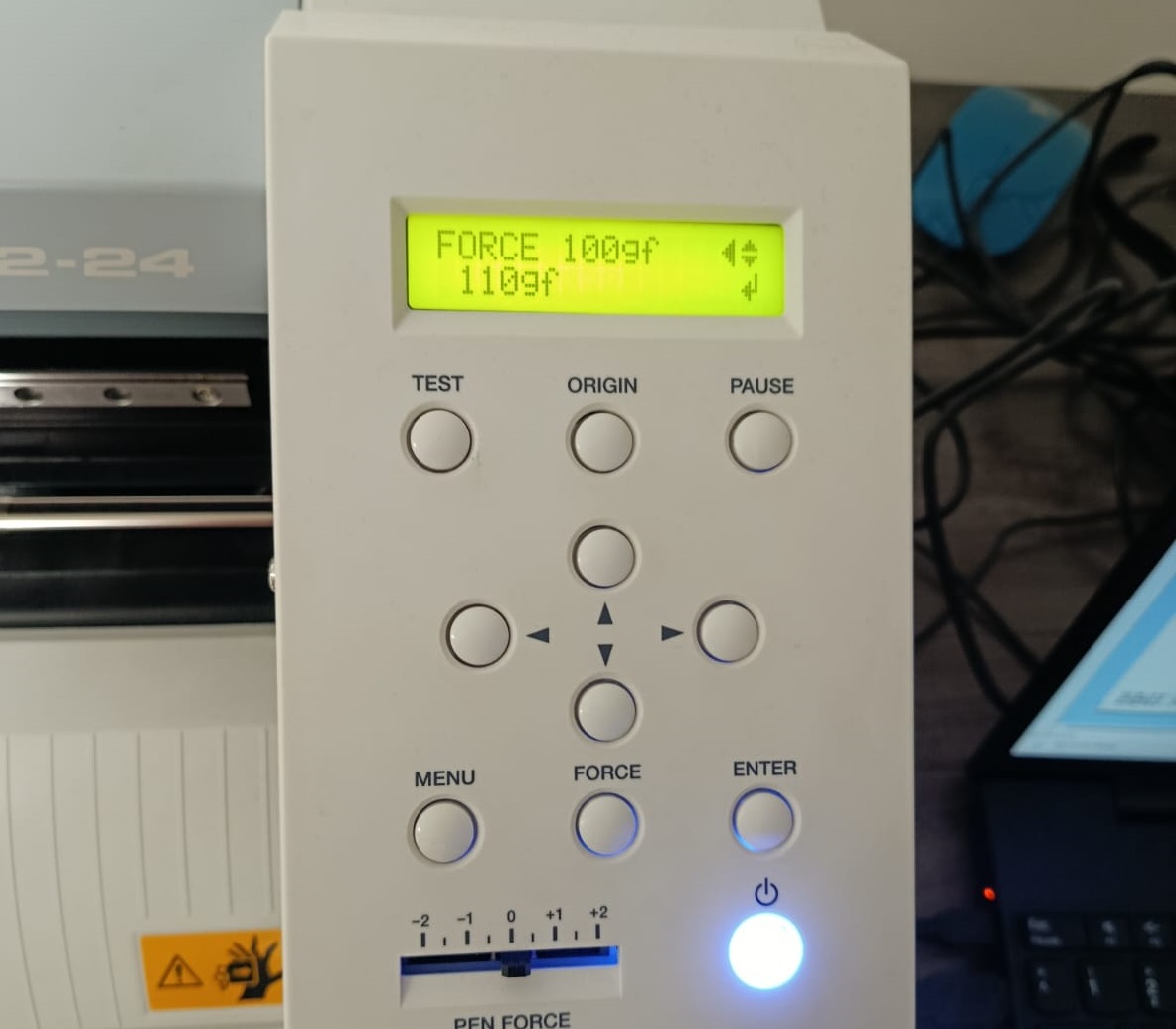
I configured the cutting force and speed on the panel. The cutting parameters used were:
| Parameter | Value |
|---|---|
| Speed | 20 cm/s |
| Force | 100gf |
| Blade offset | 0.250 mm |
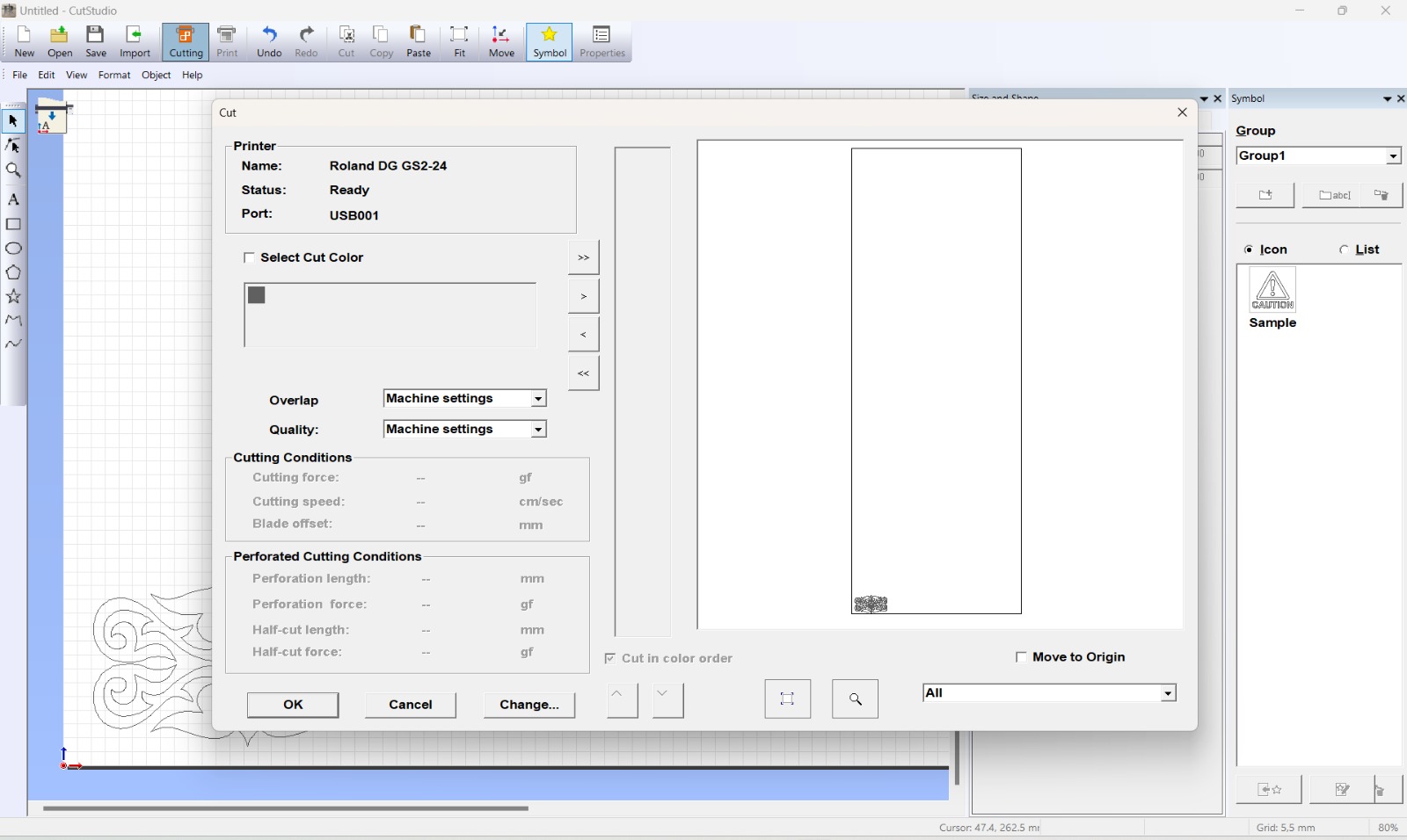
Sending the File to the Vinyl Cutter
From CutStudio, I opened the Cut dialog to send the job to the machine. It showed the connected printer, Roland DG GS2-24, ready on port USB001.
Setting the Origin Point
Once the parameters were ready, I moved the cutting head to the exact position on the material where I wanted the cut to begin. I held down the Origin button, which set that point as the starting coordinate for the job.
When I pressed Cut, the Move to Origin option on the right side of the panel was activated, instructing the machine to return to the defined origin point and begin cutting from there.
Cutting Result and Application
After cutting, I weeded the excess vinyl and applied transfer tape to the design.
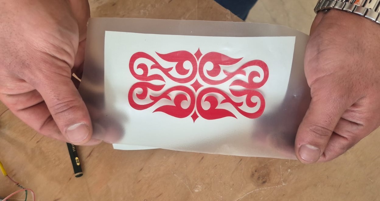
The vinyl was then applied to an HP laptop surface, aligning the design carefully before pressing down.
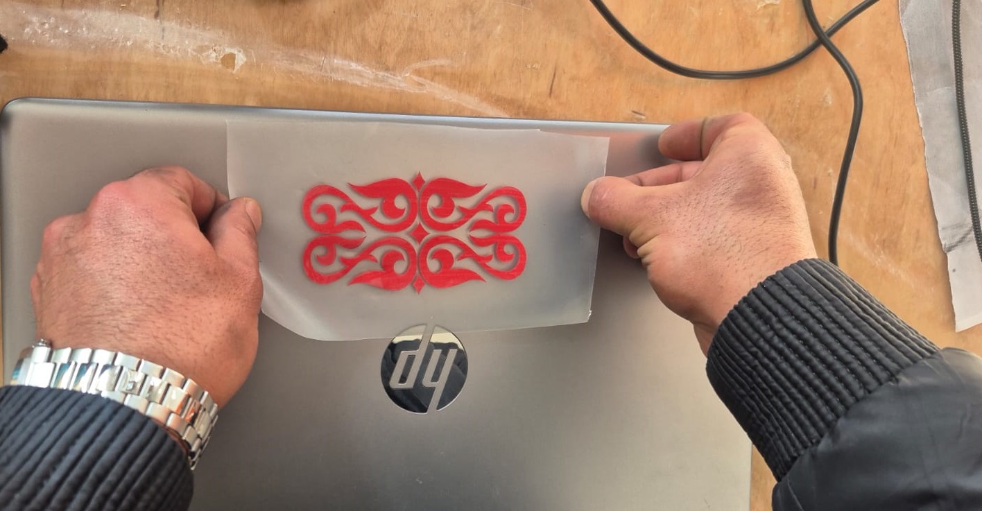
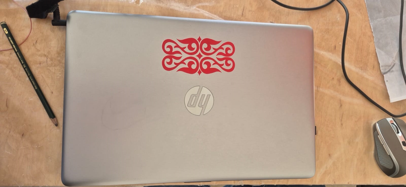
The machine executed the cut precisely, following the designed path and preserving all the fine details of the ornamental pattern.
Laser cutting
Determining the joint size
We did a kerf test, and I can measure the material thickness and size the joint width accordingly, but I still couldn’t be sure what effect that would have during assembly. To find that out, I ran a test to determine the joint thickness.
Since I might use materials of different thickness in future projects, I decided to make the joint test drawing parametric, so it could adapt to the thickness of whatever material I’m using.
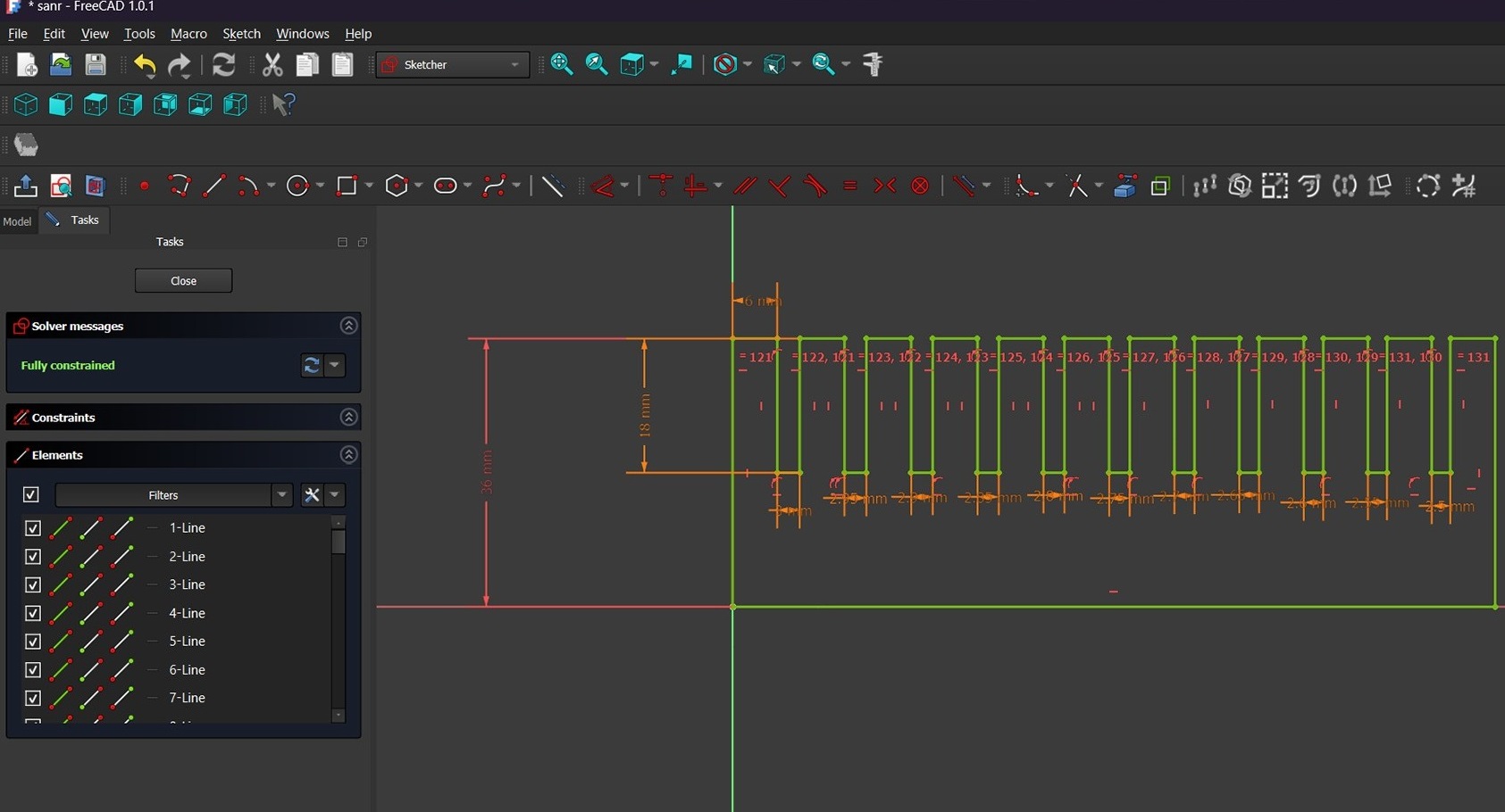
For this I used FreeCAD. First I created a spreadsheet and renamed it param for simplicity. Then I set up several parameters in it:
| Parameter name | Value |
|---|---|
| Spacing between joints | 6 mm |
| Joint length | 18.00 mm |
| Starting joint size | 3.00 mm |
| Ending joint size | 2.50 mm |
| Decrement step | 0.05 mm |
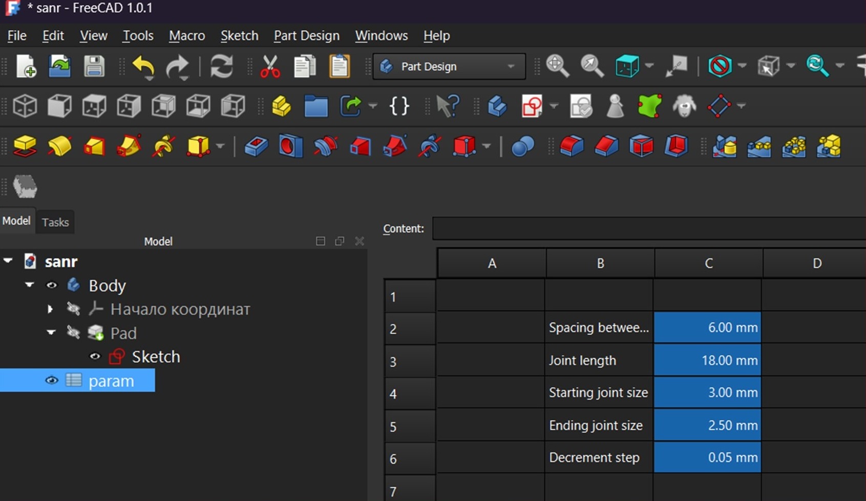
The key parameter worth highlighting is Decrement step — a 0.05 mm step is fine enough to identify which joint width fits a given material best. The Starting joint size parameter is also important, since it can be set equal to the material thickness.
After setting up the parameters, I drew the sketch:
After cutting, I checked the joints by fitting them together.
The best result was achieved at a thickness of around 2.70 mm, which gave a good balance between a tight fit and ease of assembly.
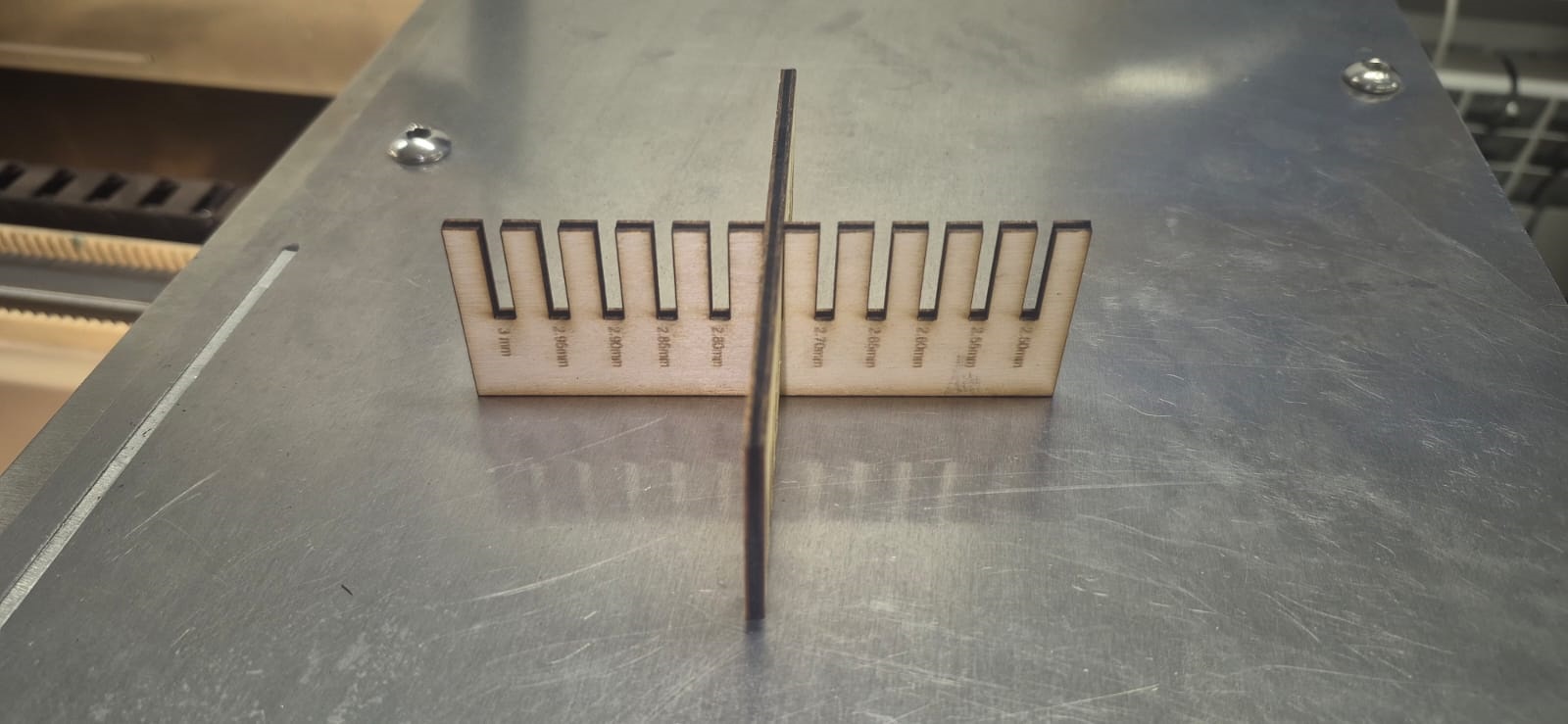
Based on this test, I estimated the machine’s kerf width at approximately 0.3 mm.
Designing the kit
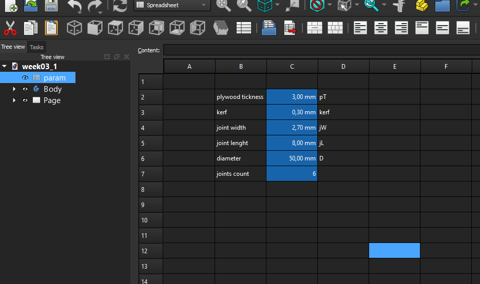
After the joint thickness test, I moved on to designing the kit. For this I again used FreeCAD. I started by creating a spreadsheet for the parameters.
I used the following parameters:
| Parameter name | Value |
|---|---|
| plywood thickness | 3.00 mm |
| kerf | 0.30 mm |
| joint width | 2.70 mm |
| joint length | 8.00 mm |
| diameter | 50.00 mm |
| joint count | 6 |
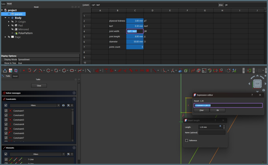
Since I might use materials of different thickness, I created a separate plywood thickness parameter, and calculated joint width using the formula plywood thickness − kerf.
The kerf value (0.30 mm) was entered directly in the FreeCAD spreadsheet as a parameter, so it is applied automatically to all joint dimensions:
To show the kerf value actually being used, here is the sketch constraint referencing it directly through an expression, =param.jW / 2, where jW (joint width) is itself calculated from plywood thickness − kerf:
I then created a Body, and inside it a sketch, drawing the base sketch which accounts for half the joint thickness and includes an angle that depends on the joint count parameter — 30 degrees in this case.
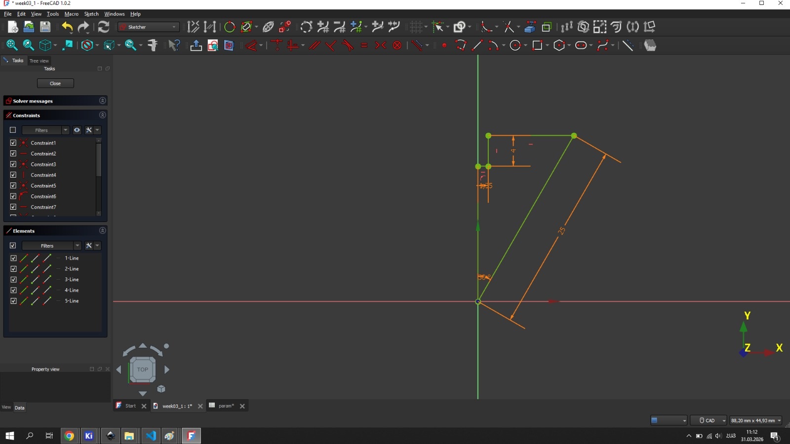
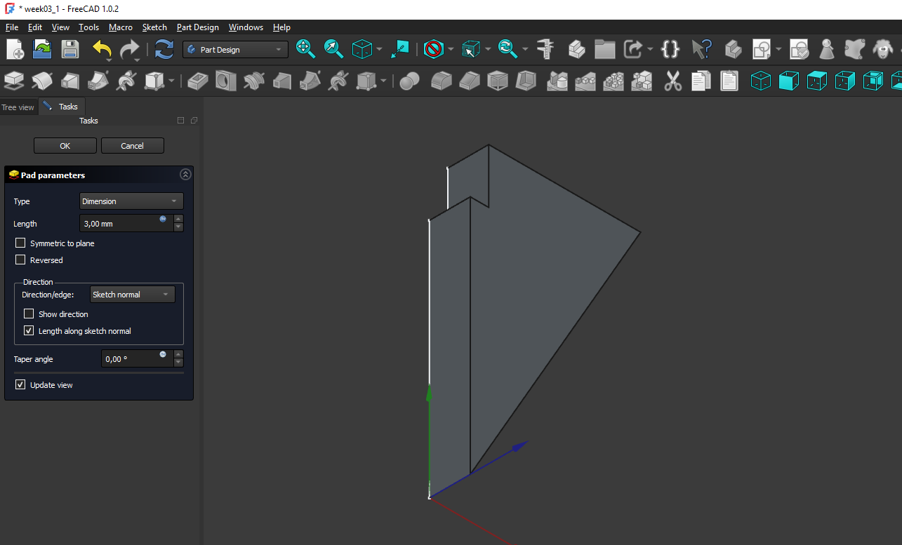
Then, for simplicity, I used the Pad tool and set its value to plywood thickness.
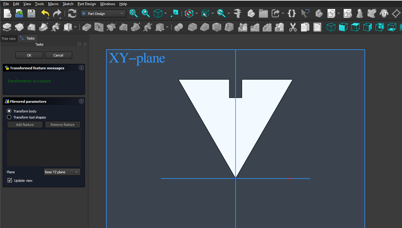
After that I used the Mirrored tool.
Then I used the PolarPattern tool and set its Occurrences value to the joint count parameter, after which the model closed up:
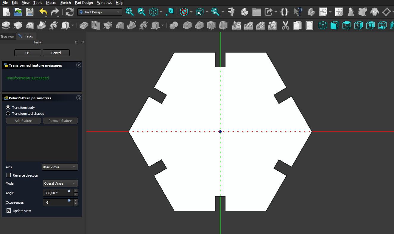
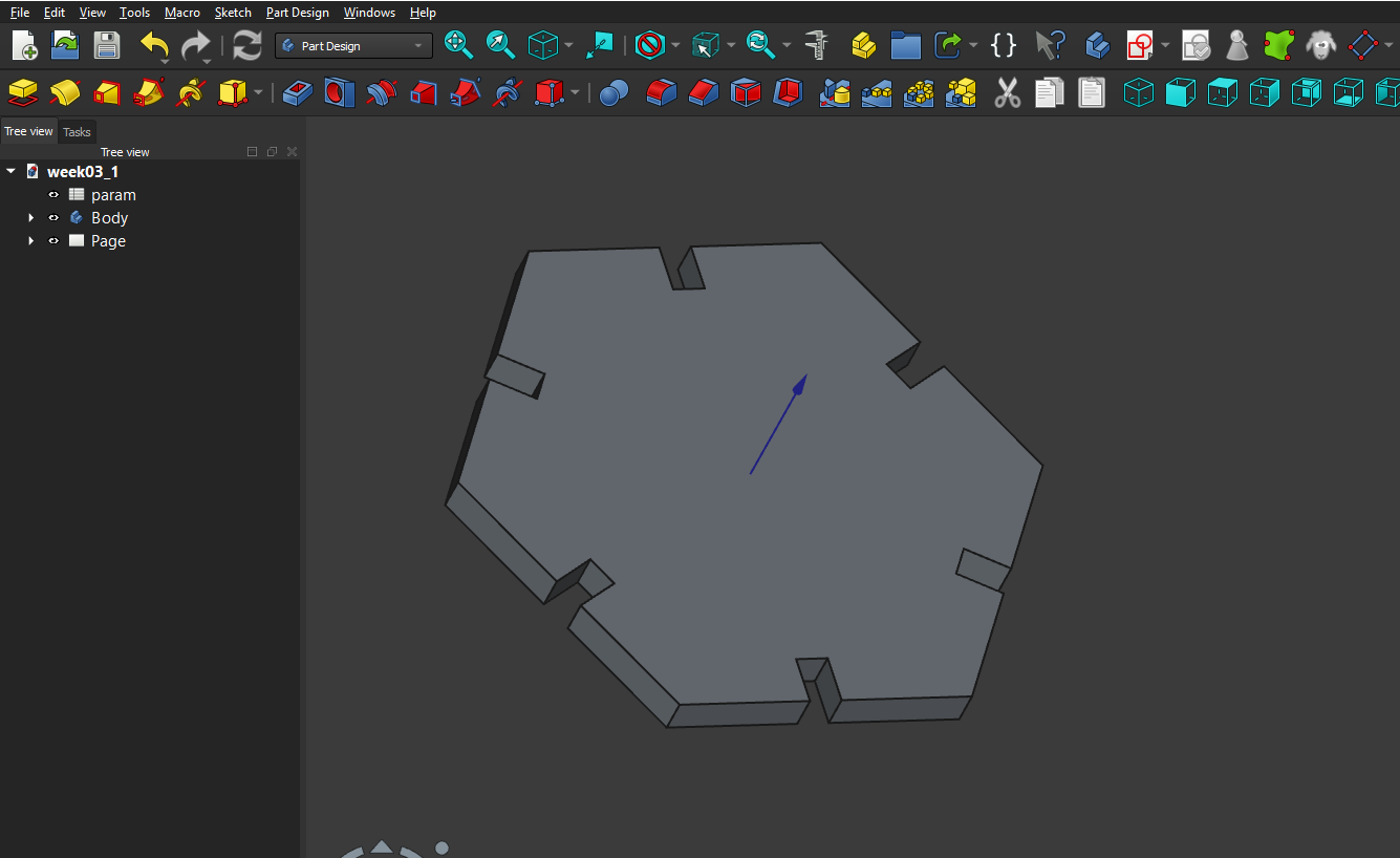
As a result, I got a parametric model that can change depending on the material thickness, the laser kerf, and can also vary in size and joint count, taking on different shapes. In my work I used a hexagon:
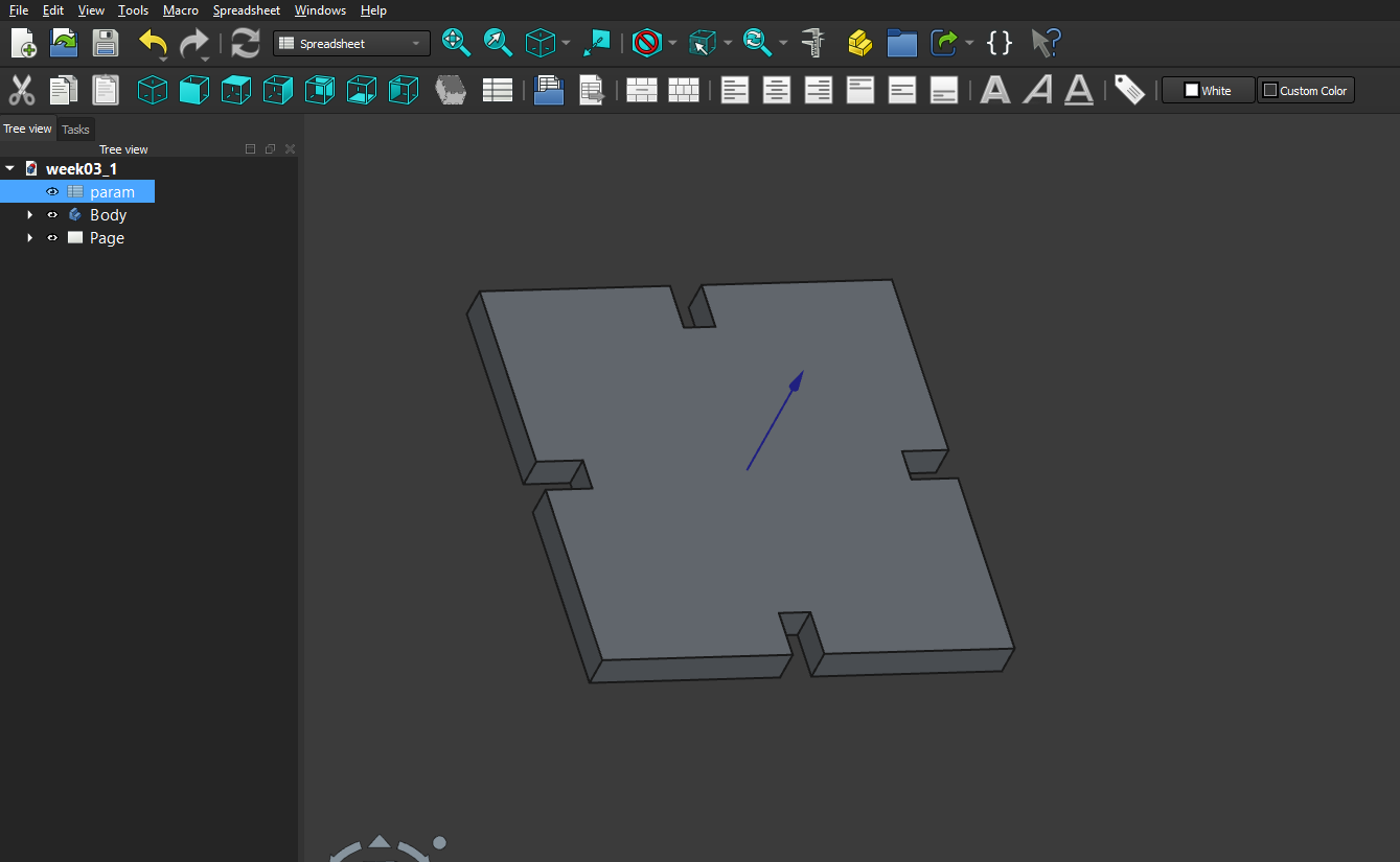
and also a square:
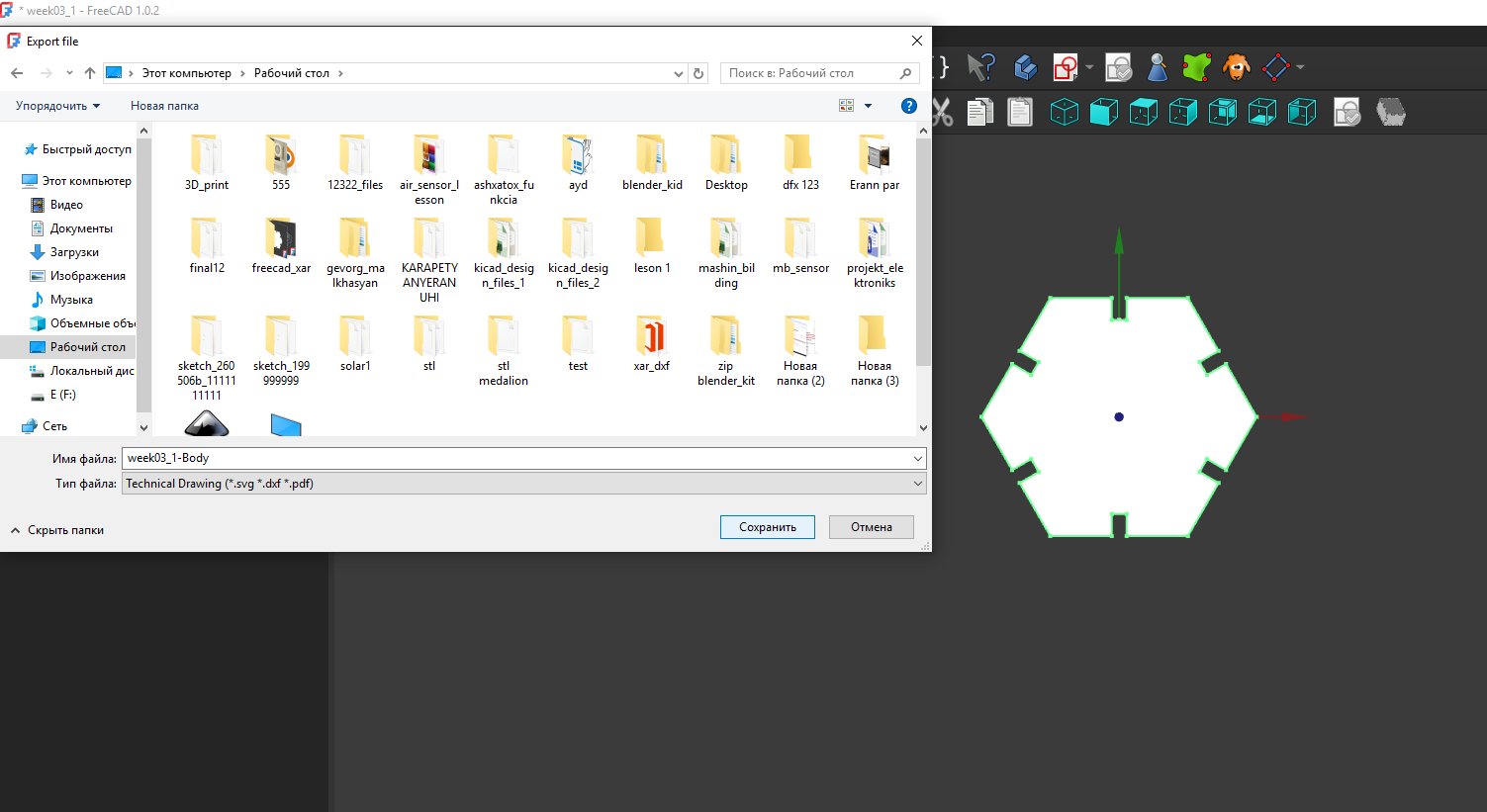
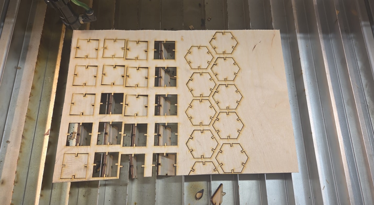
Cutting process
After completing the design, I exported it from FreeCAD as a DXF file using File → Export, selecting the Technical Drawing format (.svg .dxf *.pdf):
After exporting them as DXF, I imported them into *LightBurn and, making several copies of both, set the following cutting parameters:
- power: 70%
- speed: 10 mm/s
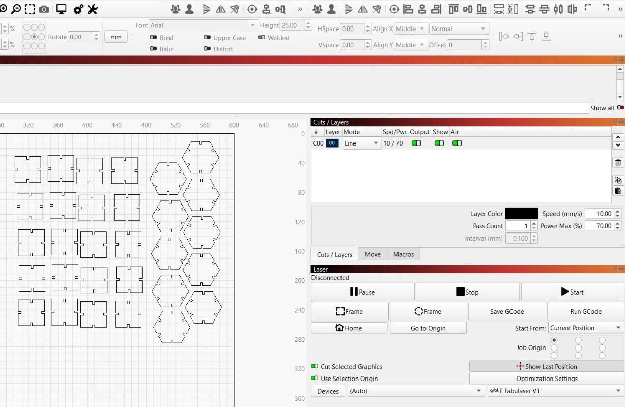
Then I cut them on the laser cutter:
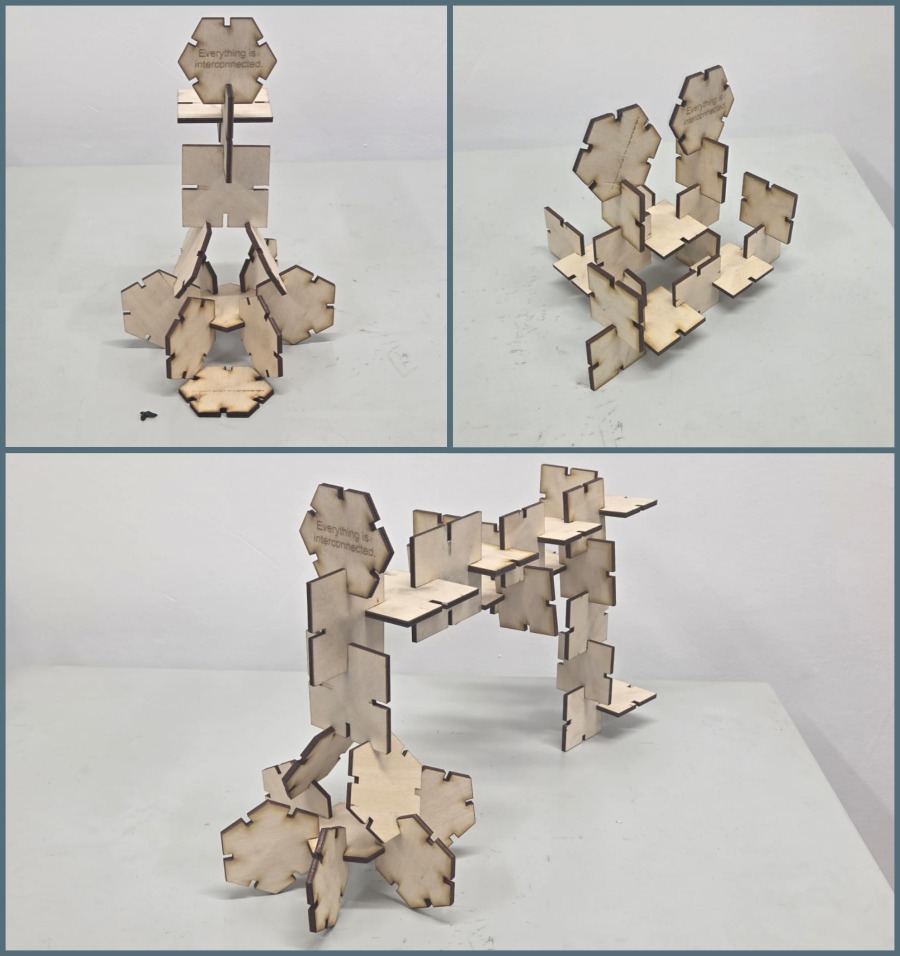
Assembly
After cutting, I assembled them in several different ways.
Conclusion
This week was quite interesting, partly because we ran into trouble during laser cutting, where the part came out larger than the dimensions set in the drawing. Finding a temporary workaround was an interesting process, since it involved some math.
The parametric model in FreeCAD also changed how I think about design. Instead of drawing fixed dimensions, I was defining relationships. When I updated the joint count parameter, the whole geometry updated automatically.
Cutting vinyl turned out to be simpler, but the workflow with the Origin button was a good practical lesson — small things like setting a reference point matter a lot when working with physical material that can’t easily be repositioned.
This week I changed my approach: instead of using the machines, I switched to understanding them.