13. Moulding and Casting
Group Assignment
- Review the safety data sheets for each of your molding and casting materials
- Make and compare test casts with each of them
- Compare printing vs milling molds
During the group assignment, our instructor Mkhitar Avoyan from Fab Lab Dilijan introduced us to various types of molding and casting. It was very interesting because it was closely related to my professional field. The types were diverse:
- Sand Casting
- Die Casting (Metal Die Casting)
- Investment Casting
- Gravity Die Casting
- Continuous Casting
- Shell Molding
- Lost-Foam Casting
- High Pressure Die Casting
- Centrifugal Casting
- Permanent Mold Casting
- Vacuum Casting
- Low Pressure Casting
- Squeeze Die Casting
- Plaster Casting
- Aluminum Pressure Die Casting Machine
After that, we studied different forms of molding. He showed how molds are created using milling and 3D printing, and explained the various materials used, including wax, metal, plaster, plastic, and silicone. The use of these materials in mold making depends on the type of casting and its specific characteristics.
After all this was explained, we began our group work. Since the tasks were different, we decided to distribute the process among ourselves while each participating in the overall workflow. This organized approach gave us the opportunity to conduct many experiments.
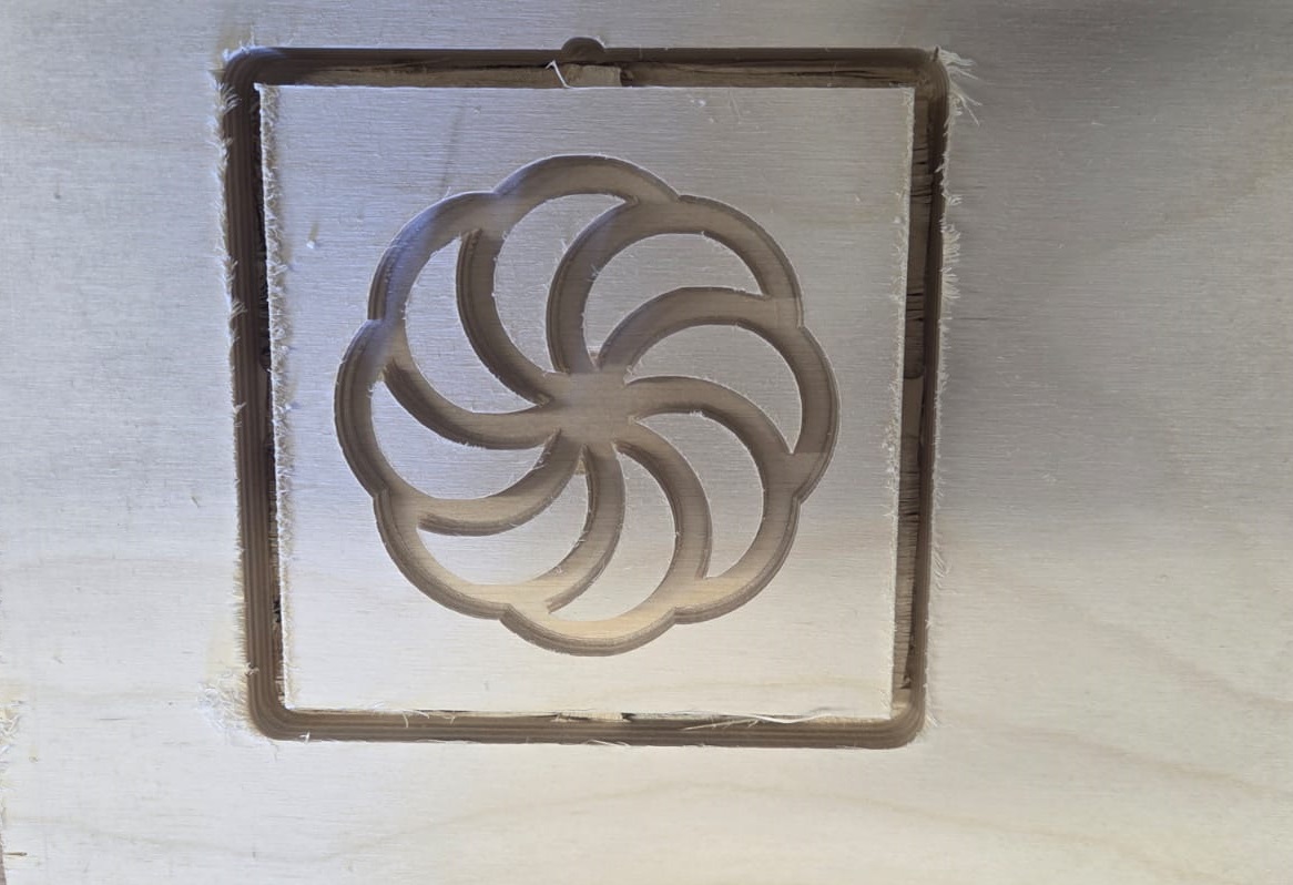
The group work started with Hrach preparing the 3D model. We had to complete our assigned tasks using that model. I used a CNC milling machine to engrave the model on plywood.
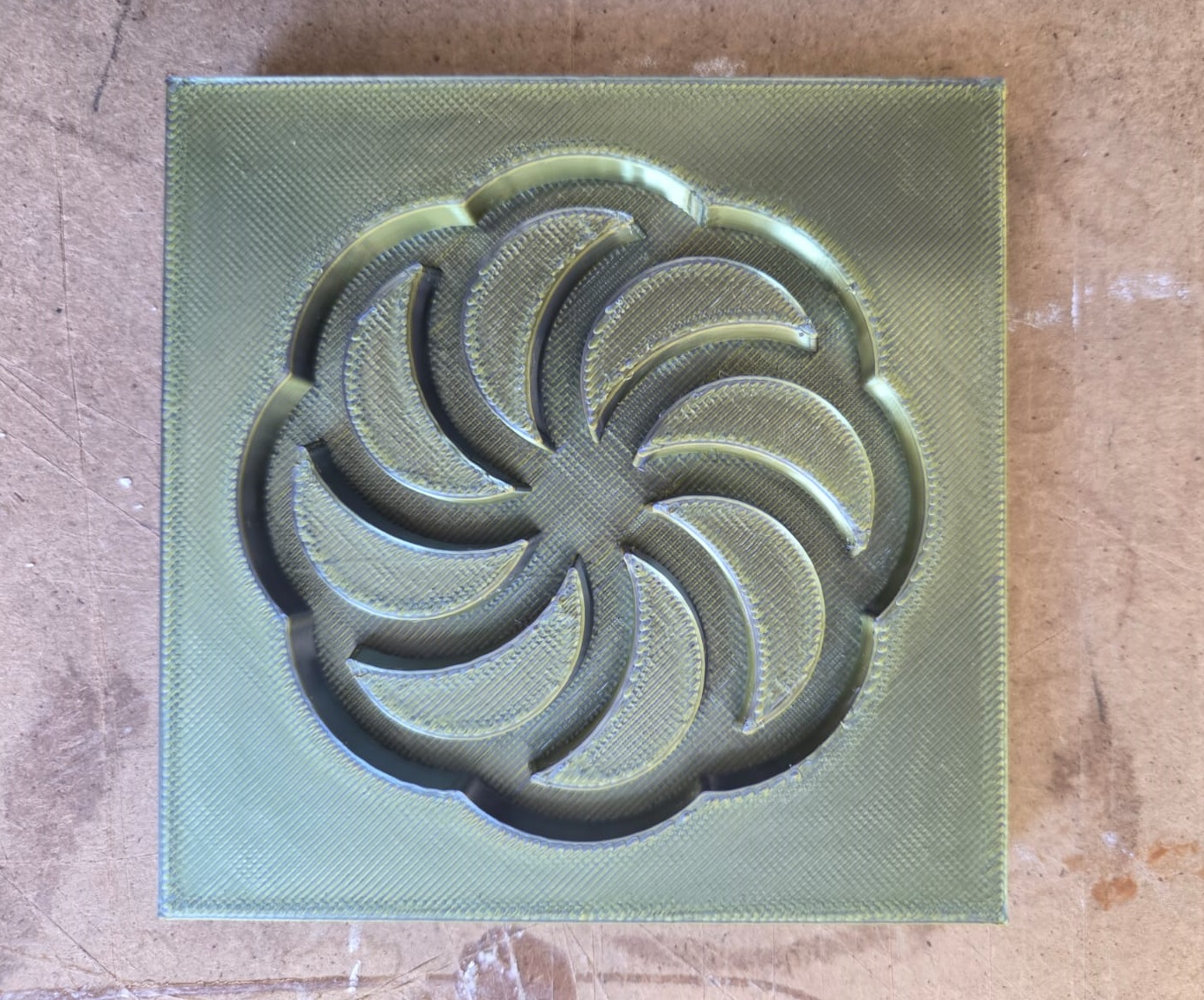
We also obtained a mold from that pattern using 3D printing and tried casting with different materials.
I tried filling the engraved layered wood with plaster. Since wood has a sponge-like property of absorbing poured material, I coated it with a special oil layer so that after plaster casting it would come out of the mold easily. Then I mixed plaster with water until it was viscous and fluid, so it would spread throughout the entire mold when poured. After pouring the plaster, we removed air bubbles using vibration — this is key to a good quality cast.
After doing everything correctly, I made a mistake by rushing to remove the cast from the mold.
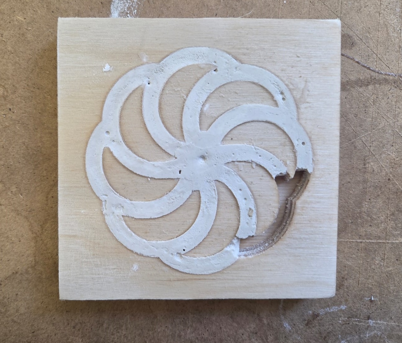
Since it had not fully dried and hardened, it broke. From this experience I learned that in this case, rushing and not fully drying the material leads to failure. And so we continued casting with various materials. After finishing the group work, it gave us a lot of knowledge and hands-on experience.
You can see our other experiments on our group page.
Individual Assignment
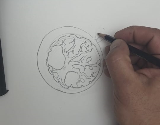
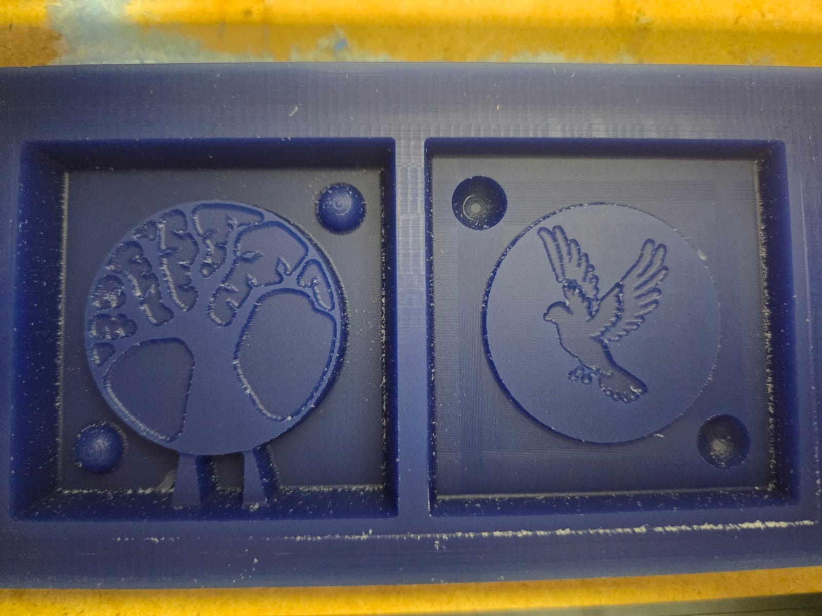
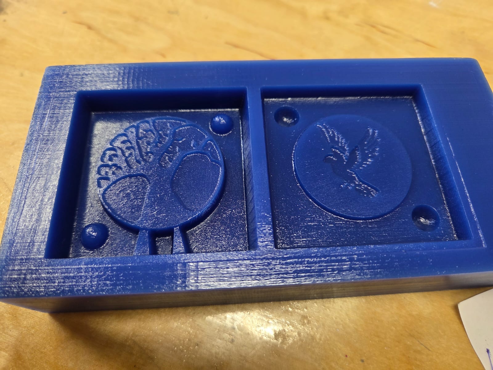
For the individual assignment, I had to prepare a mold using any of the types we had studied. The one that interested me the most was the method of engraving in wax. I had many different ideas. I decided to make a double-sided medallion — one side featuring the “Tree of Life,” and the other side Noah’s dove with an olive branch in its beak. I first tried to illustrate all of this on paper to better understand the design.
Mold Design in FreeCAD
3D Modeling the Medallion
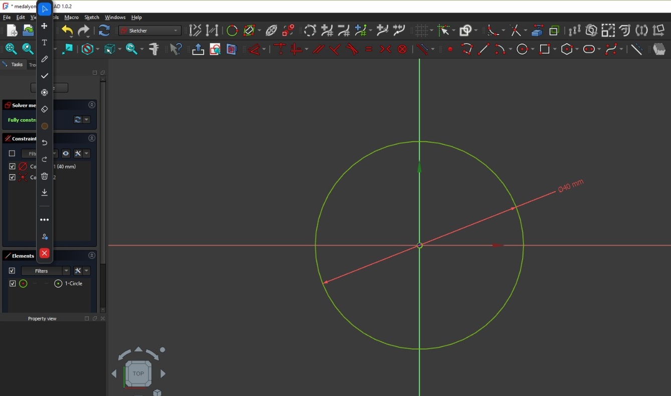
To obtain the medallion, I created a circle with a radius of 40 mm.
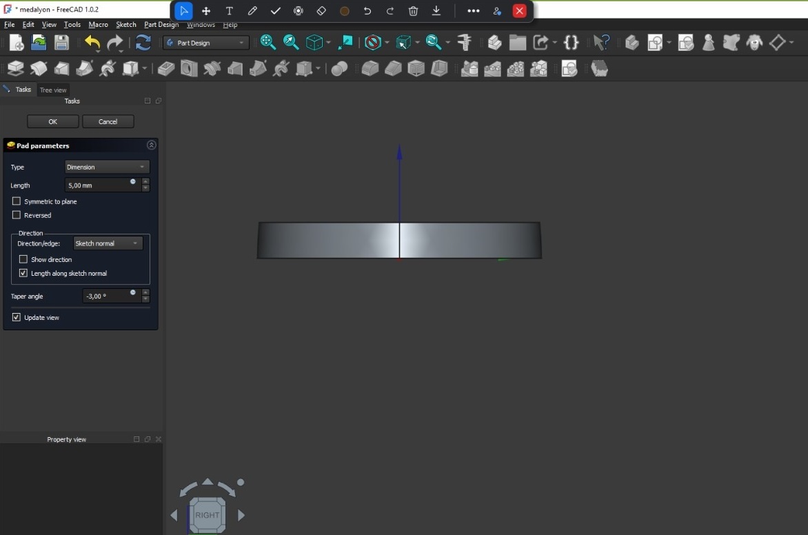
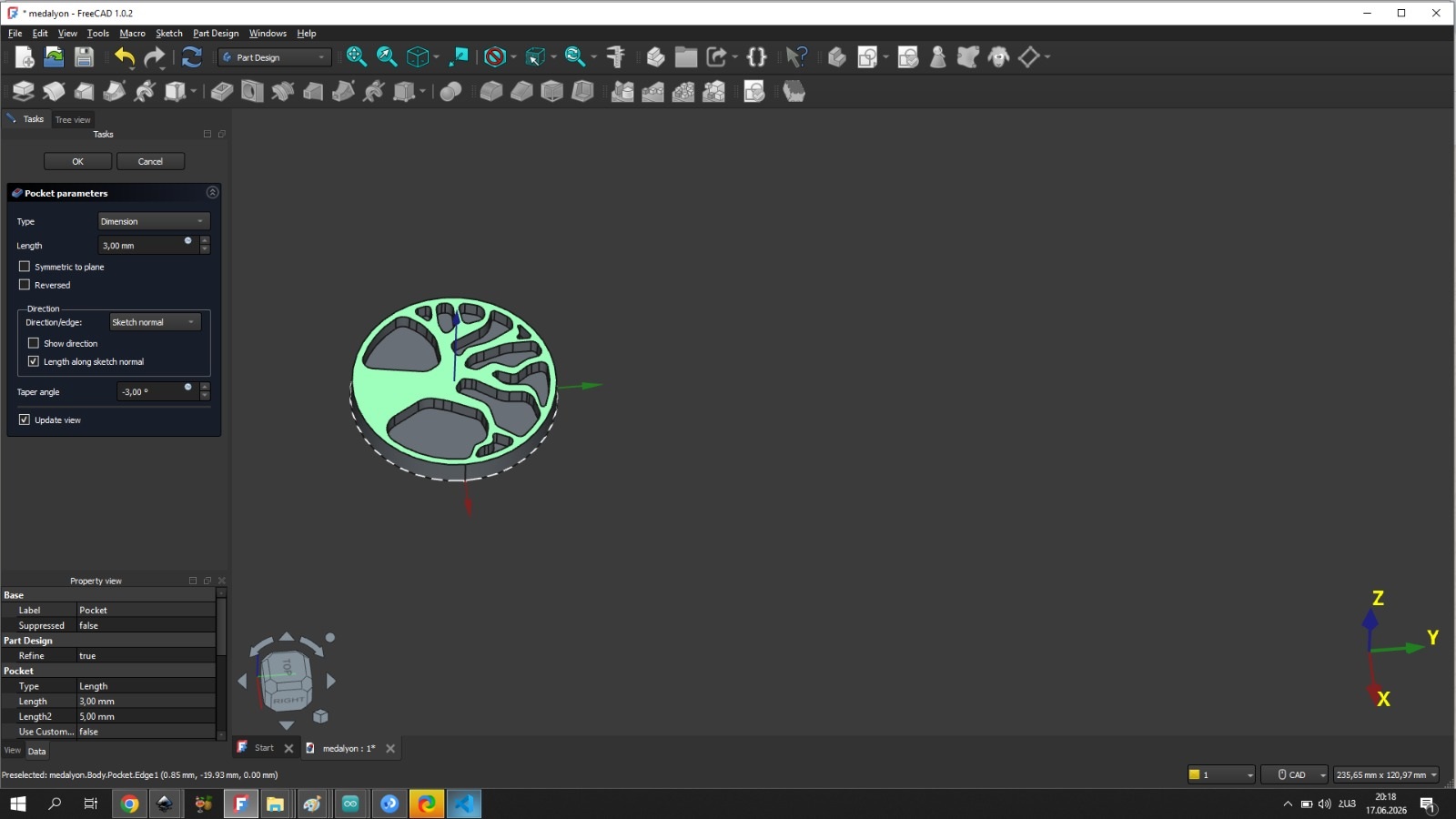
Then, in Part Design, I made a Pad, specifying the parameters: length — 5 mm. Recalling the knowledge we gained from the group assignment, I set the taper angle to -3 degrees so that it would be easier to remove from the mold when used as a mold.
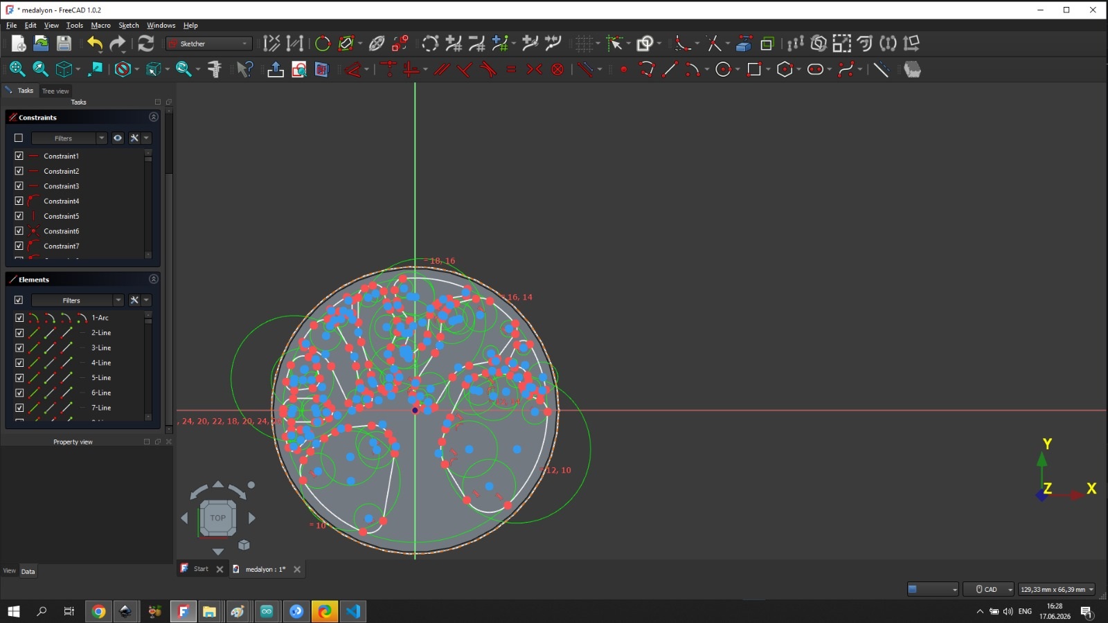
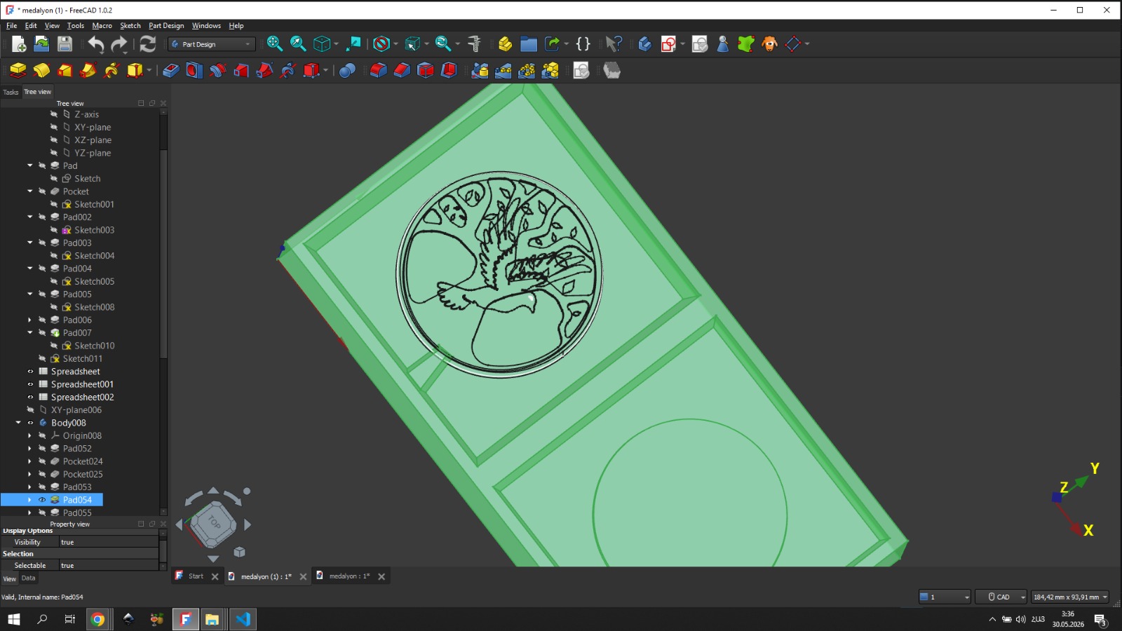
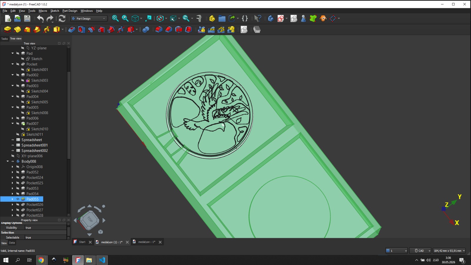
After that, I created a tree sketch on the padded part, and that is where the problems began. The problem was that in FreeCAD, when drawing a sketch with many lines and points, FreeCAD starts to perform poorly and becomes slow. This issue complicated my workflow, but since I was determined to fully realize my idea, it did not become an obstacle to bringing the sketch to its logical completion.
After drawing the tree sketch, which represented one side of the medallion, I performed a Pocket operation in Part Design. I set the parameters: length 3 mm and taper angle -3 degrees, as mentioned at the beginning. However, it would have been preferable to set a larger angle, for example, -7. I was unable to do so because when I pressed the confirm button with a taper angle of -7 degrees, the message “BRep-API command not done” appeared.
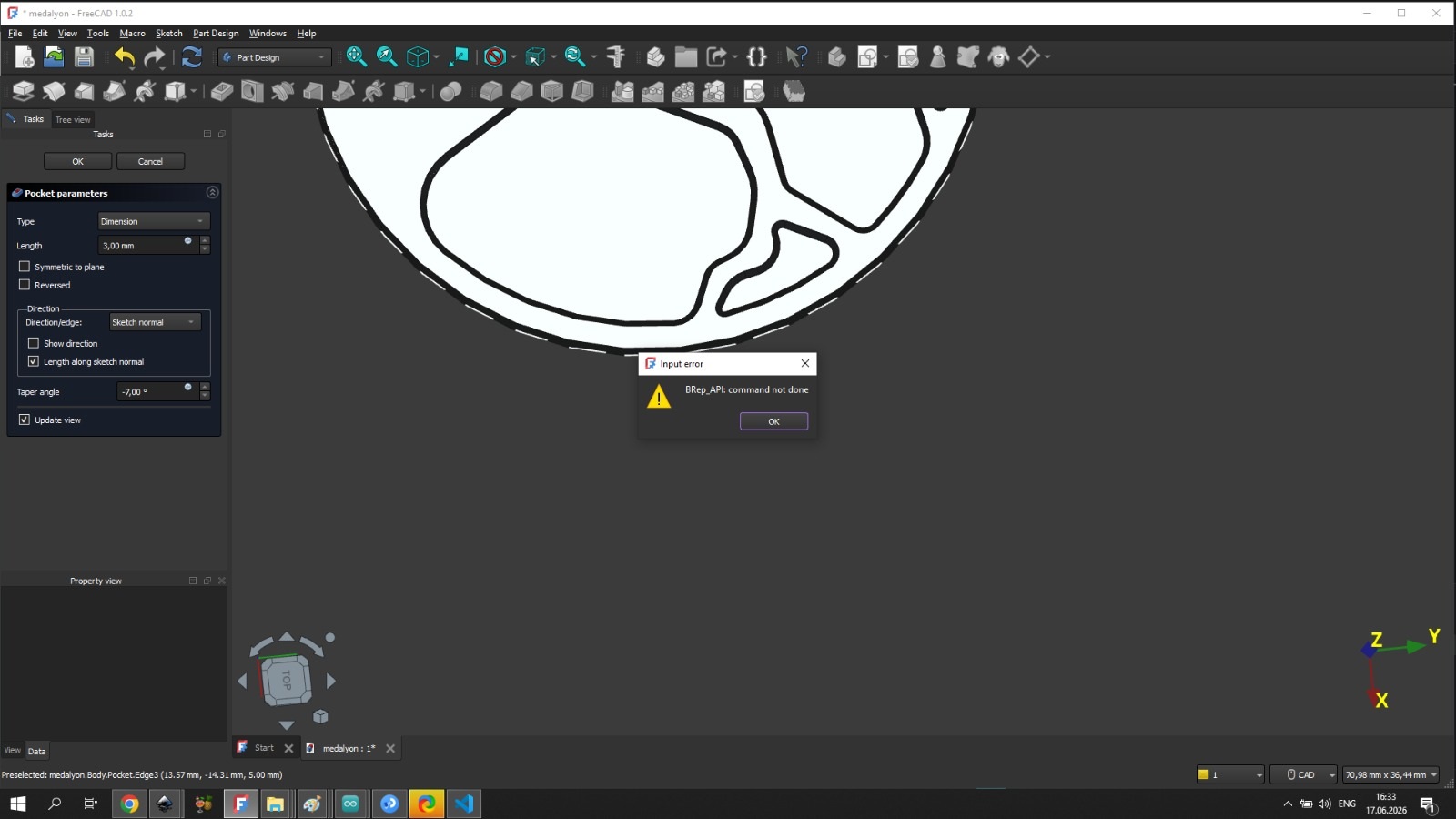
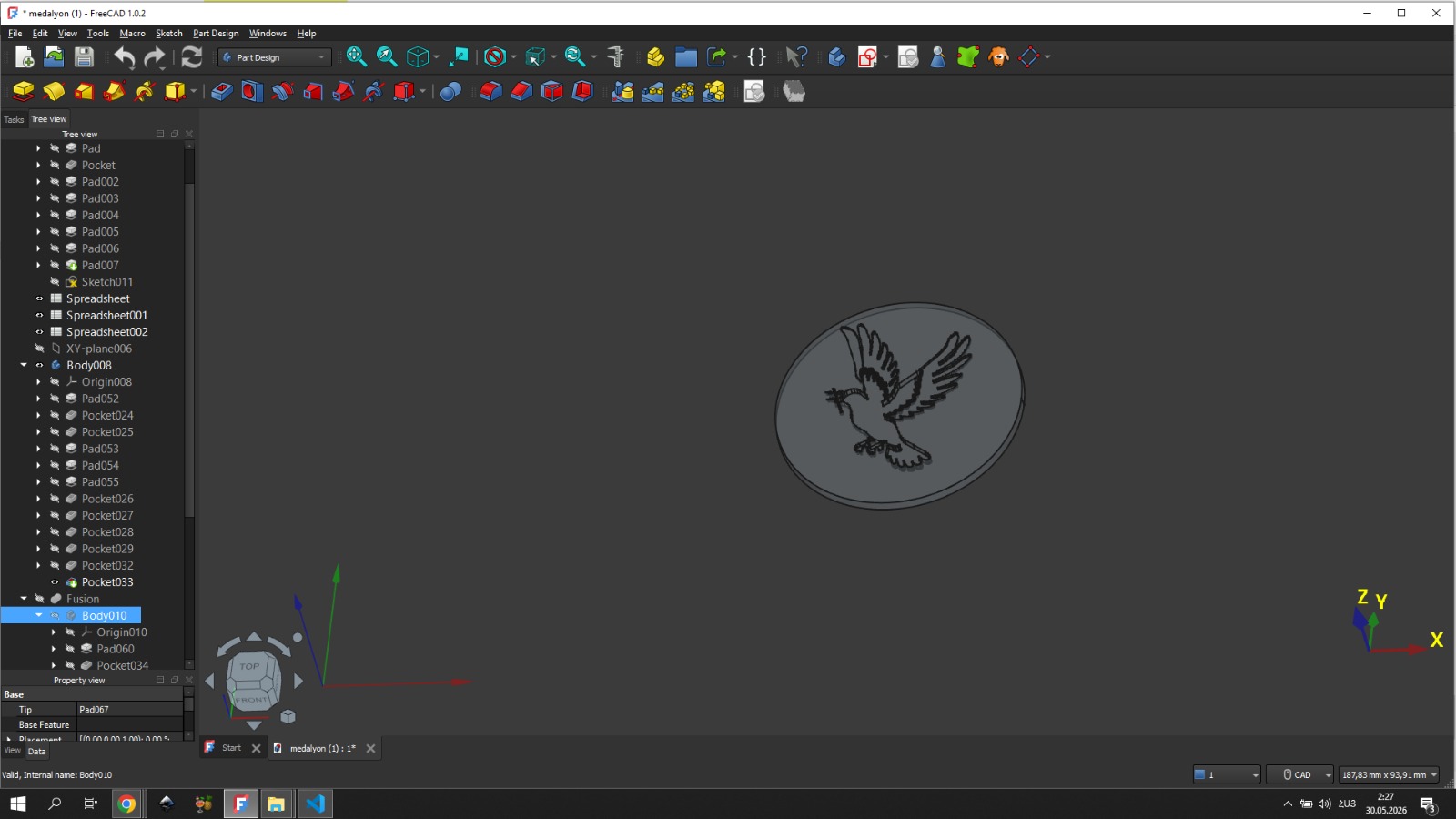
After that, I reduced the value until the software allowed me to confirm the operation. The confirm button worked with a taper angle of -3 degrees. Having obtained one side of the medallion, I then completed the other side using the same principle, where a dove was depicted.
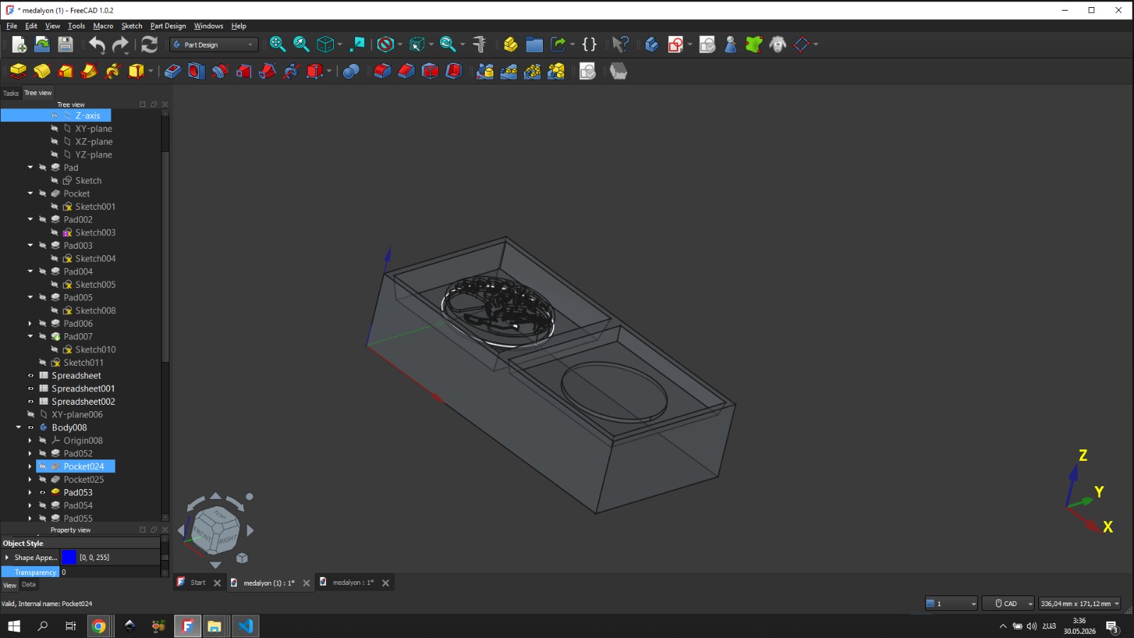
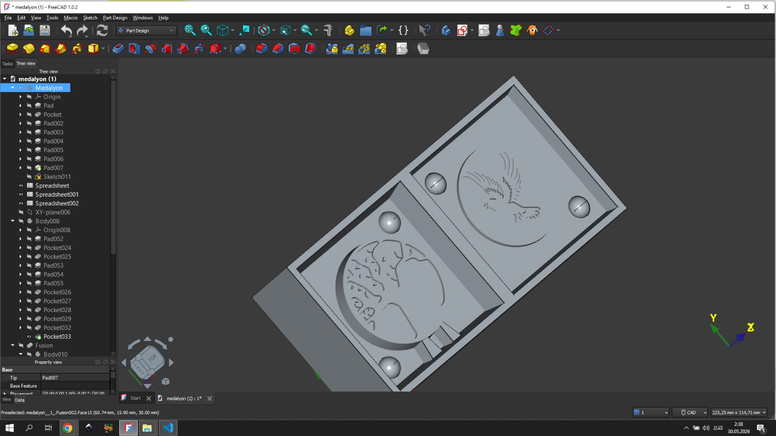
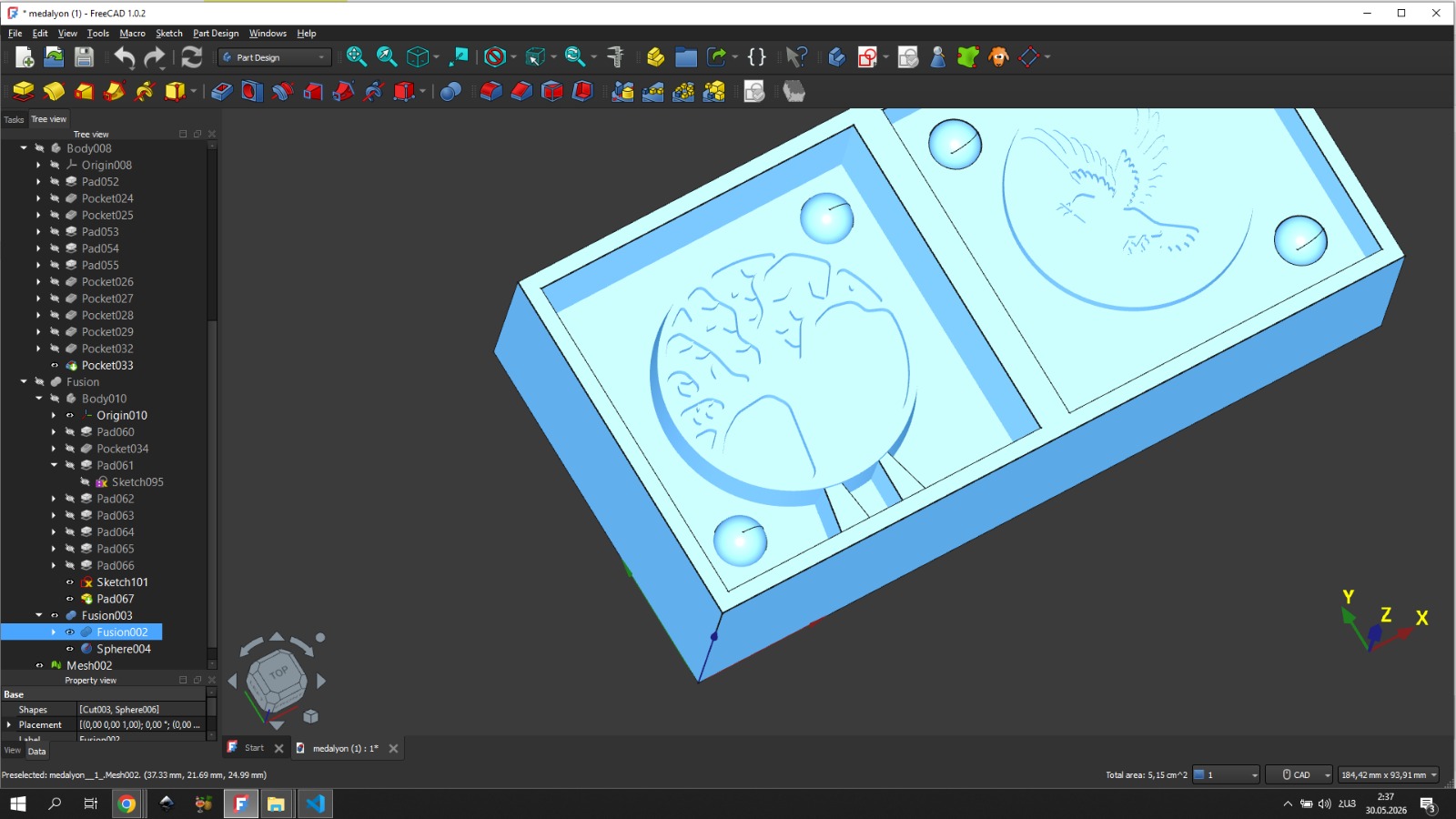
Modeling the Wax Mold Body
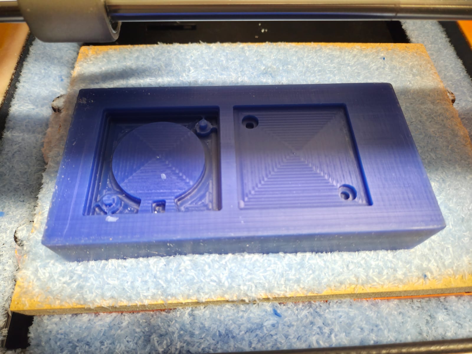
After completing the 3D model of the medallion, the next step was to model the wax mold itself. I placed the medallion’s 3D model into FreeCAD, created a body, and within it created a sketch with the pre-cut wax dimensions to get a rectangle with those dimensions. Then I closed the sketch and used the Pad tool in Part Design to get the pre-cut wax dimensions.
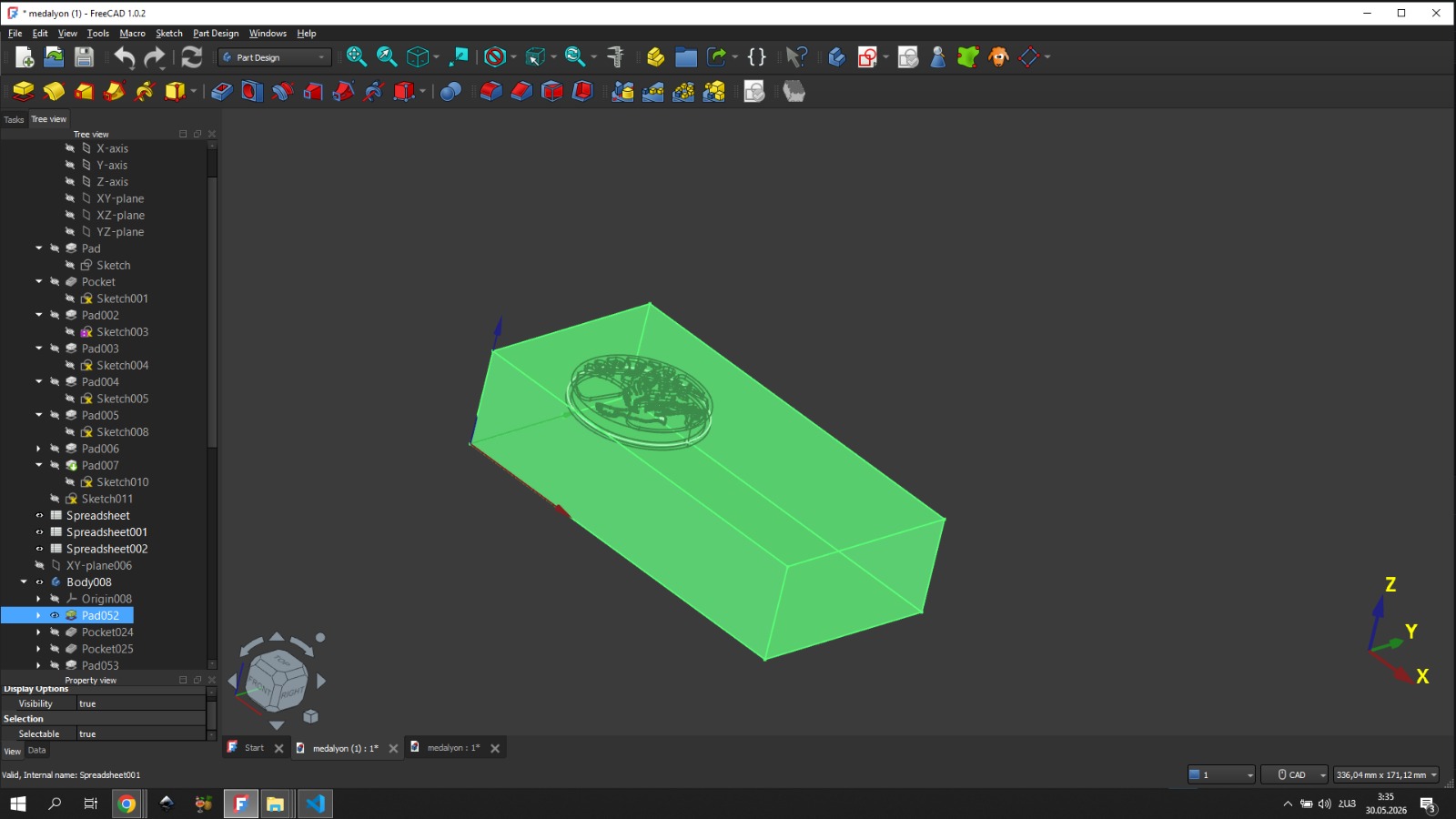


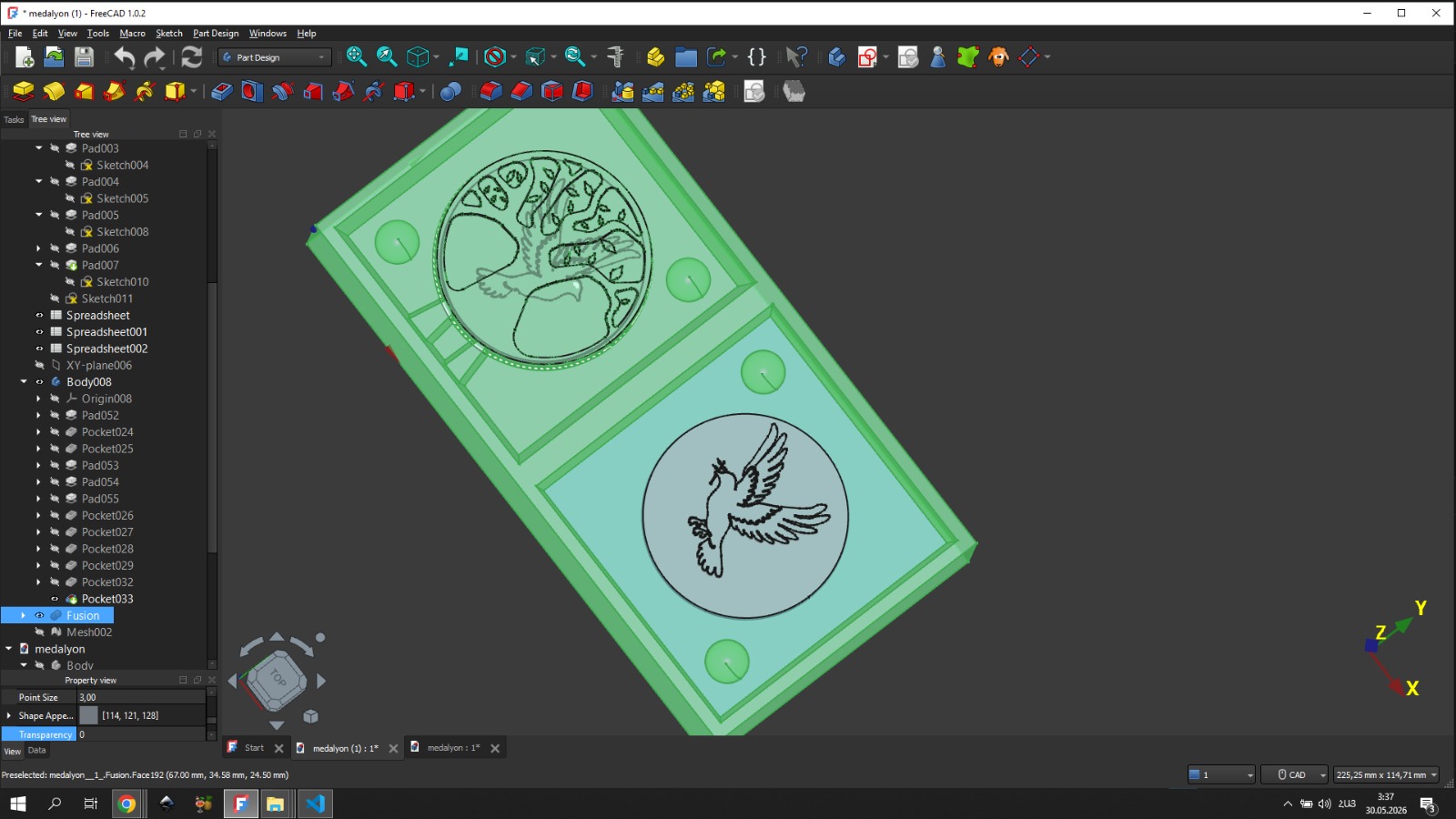
On the wax I then obtained 2 equal squares that would become the outer walls of our mold. In short, by engraving those 2 squares into the wax, one would contain one side of the medallion and the other would contain the other side.
From the knowledge gained during group work, we knew that the mold must have a special opening through which the corresponding material would flow into the mold during casting.
CAM — Toolpath Generation and Milling Process
Also, to keep the mold stationary, I added 2 protruding hemispheres at 2 corners of one side, and on the other side of the mold at the same positions I added matching hemispheres — but recessed inward.
Rough Pass
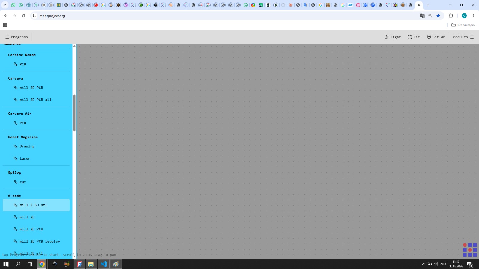
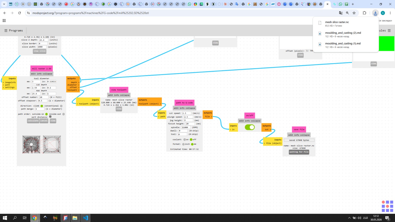
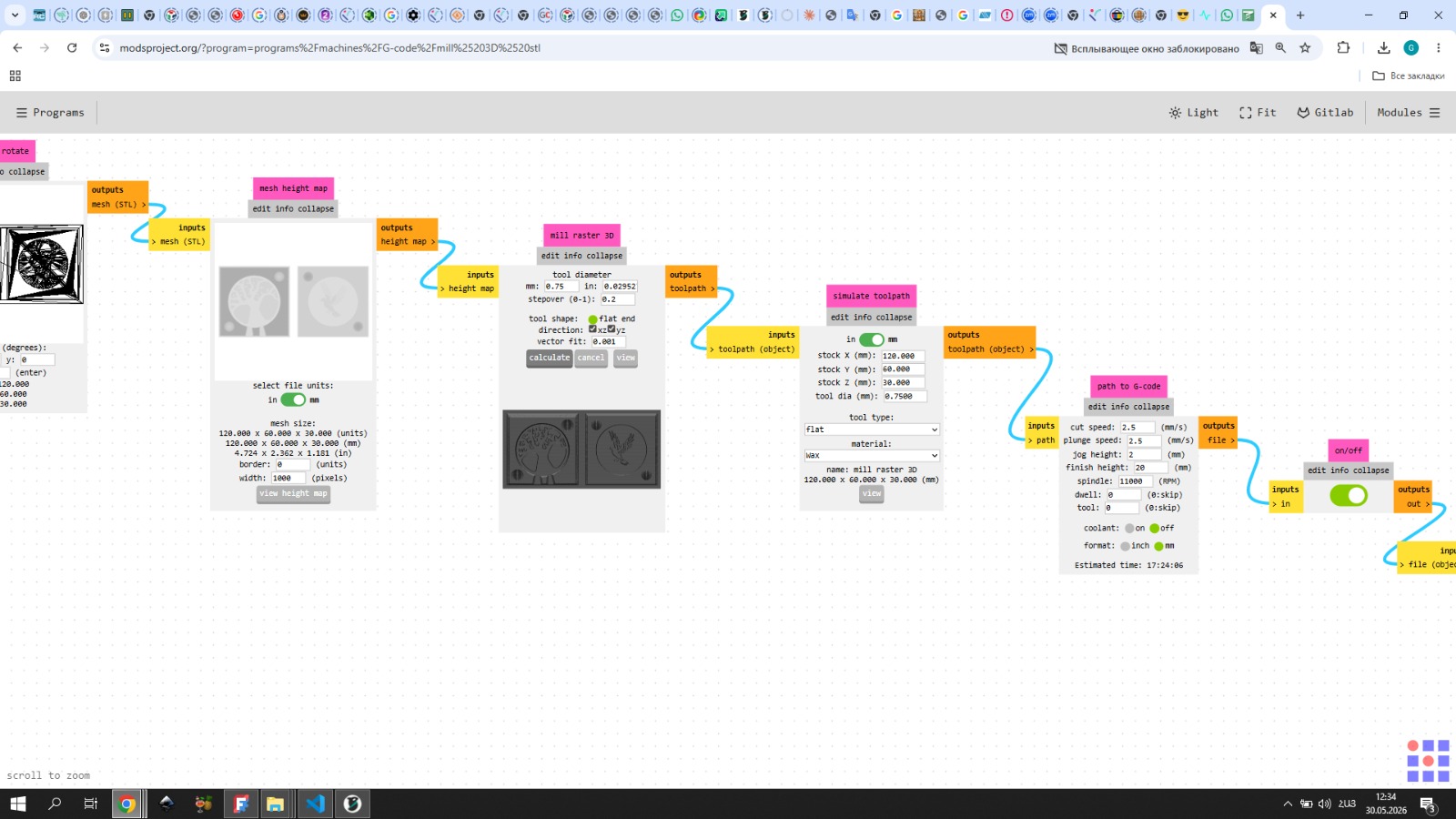
After 3D modeling, the next important step was generating G-code using the mods projects platform.
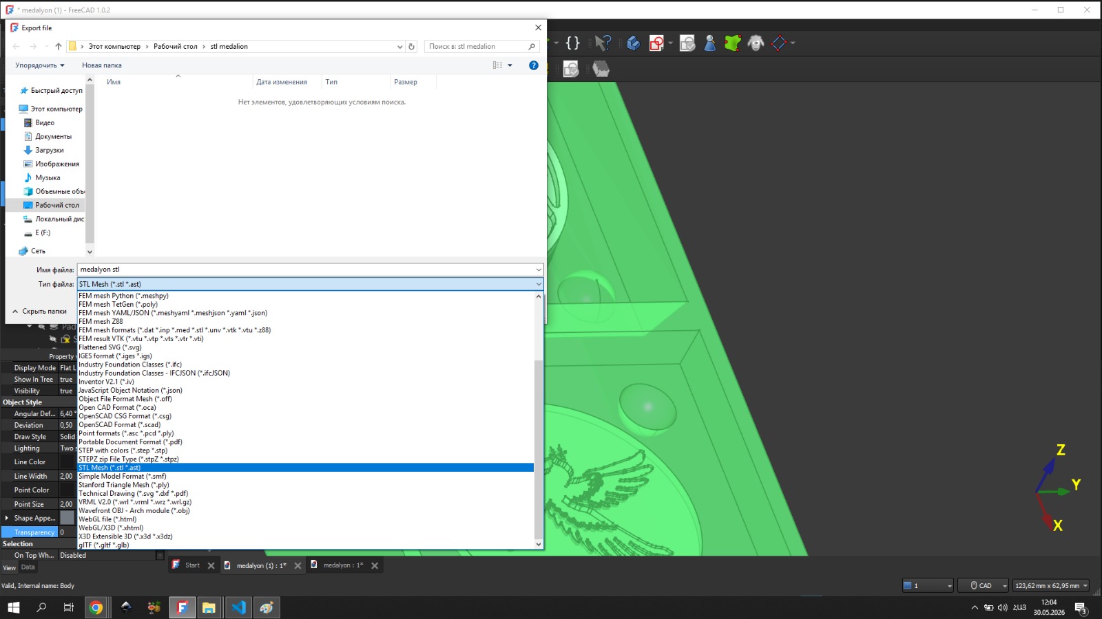
I exported the STL file, then opened it in mods using the G-code 2.5D STL module.
For the rough pass I used a 3 mm flat end mill. I set the tool diameter to 3 mm and the offset to 10, so that the number of passes would be just enough to cover the surface.
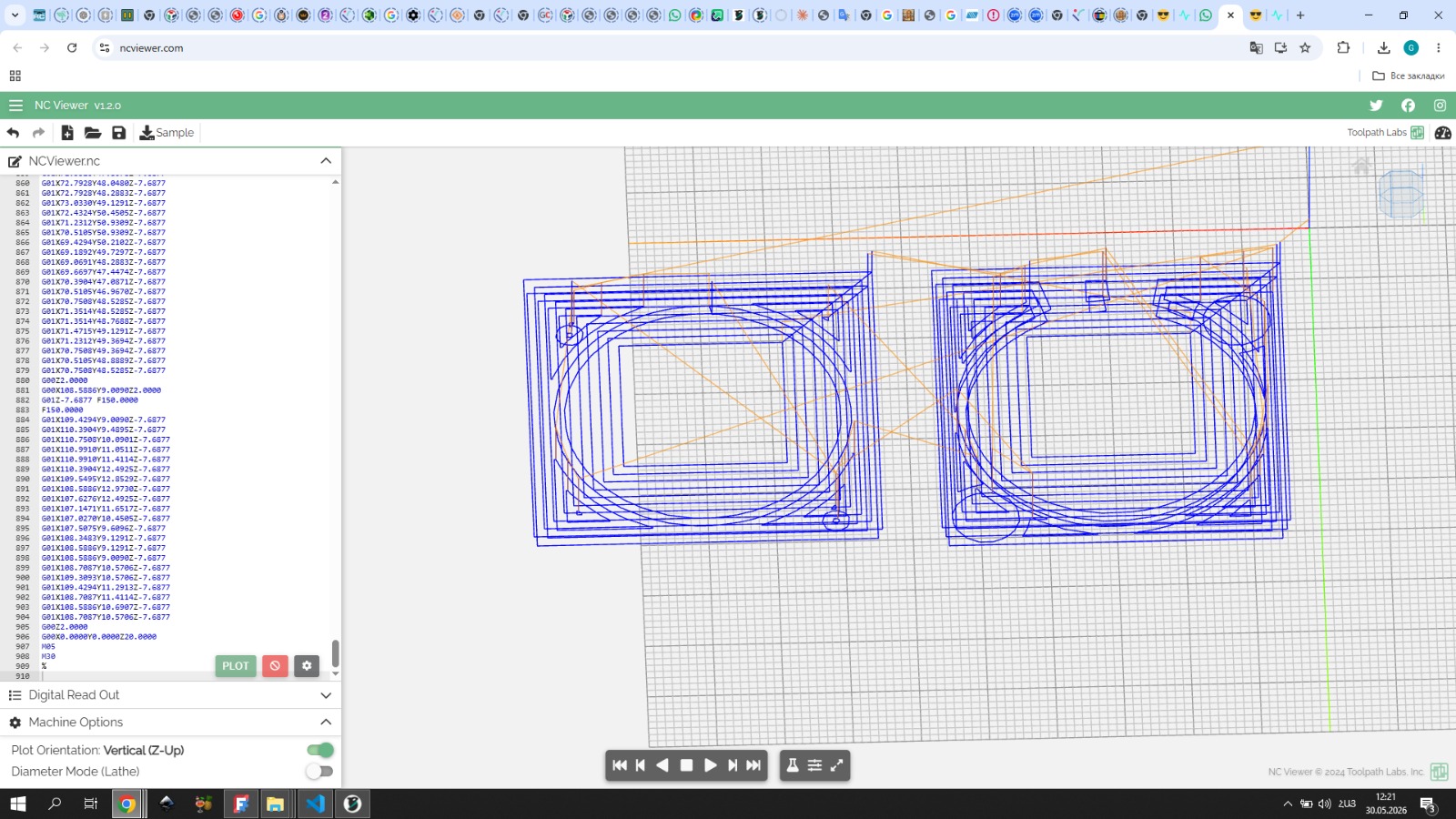
I then ran the calculate function. However, the result did not look very clear in mods, so after it turned save I opened the NC file in Visual Studio Code and copied the code.
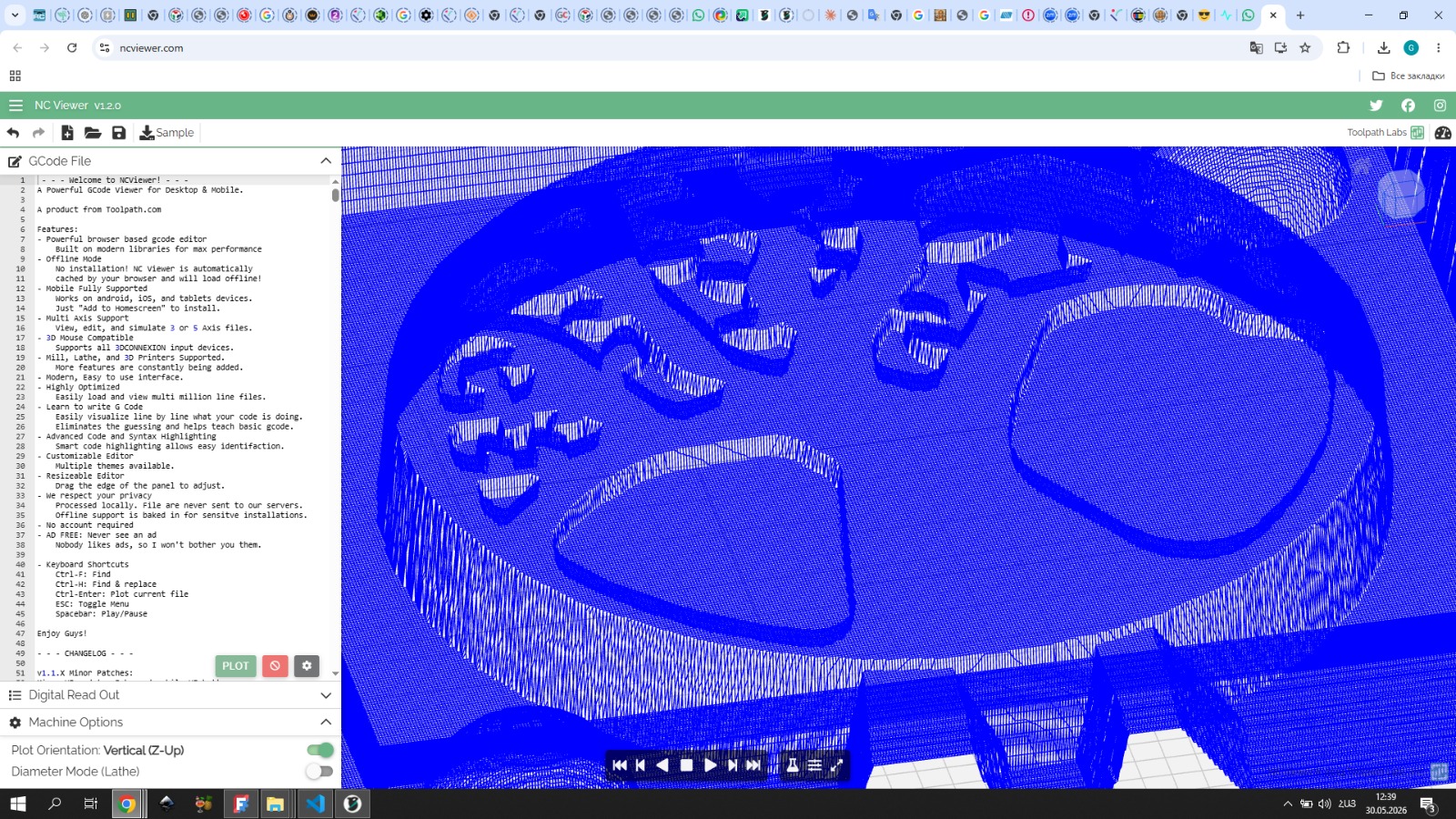
I pasted it into ncviewer.com — where the toolpath looked much better and I could clearly see how it would work. After that I started the engraving.
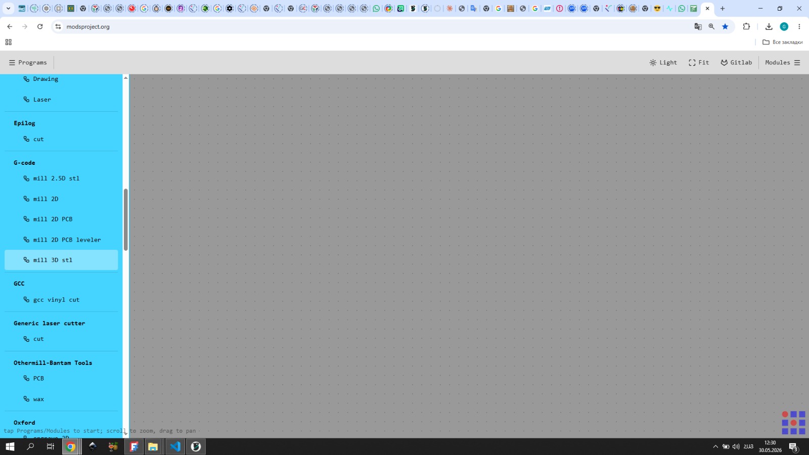
Finishing Pass
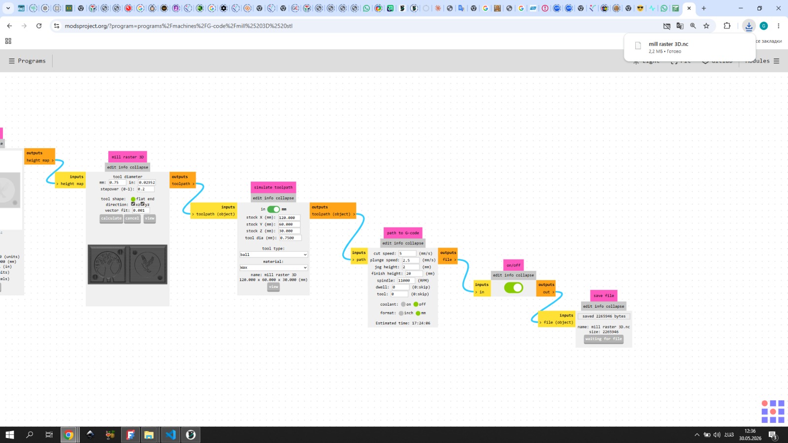
For the finishing pass, I opened the same STL file in mods again, this time using the mill 3D STL module.
For this stage I switched to a 0.75 mm flat end mill to achieve finer detail. I chose this size as a starting point — if the result wasn’t satisfactory I could go smaller, but with 0.75 mm I wouldn’t have to wait too long.
I set the stepover to 0.2 and the cut speed to 2.5 for a more precise and detailed engrave.
To verify the toolpath I followed the same process as with the 3 mm pass — opening the file in Visual Studio Code and copying the code.
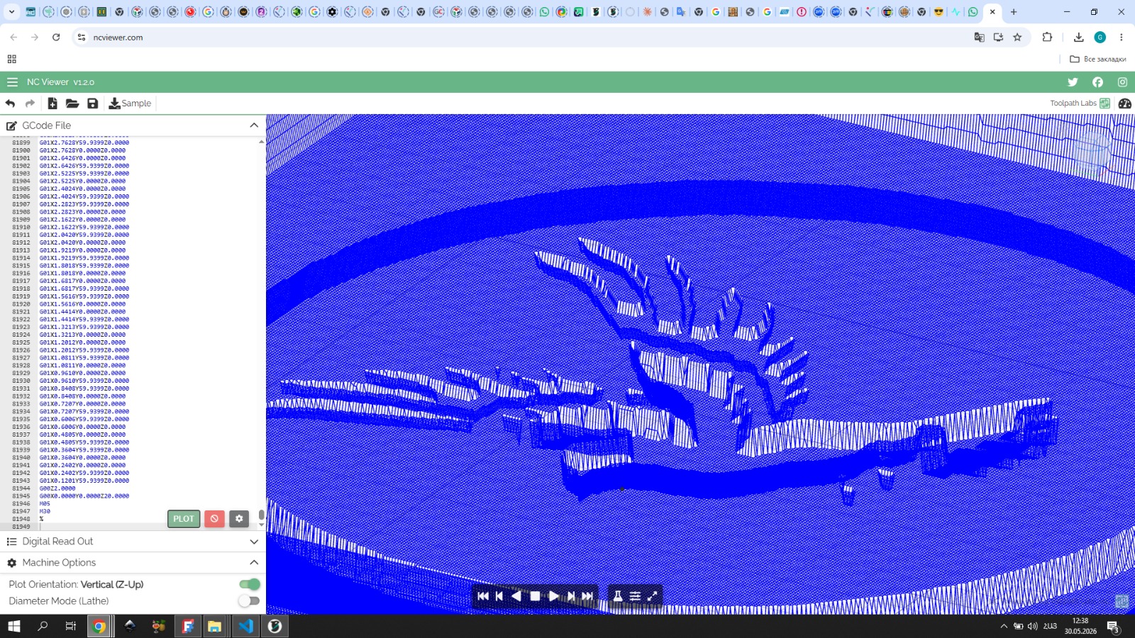
I pasted it into ncviewer.com — the result looked great and I proceeded with the engraving.
After the final work on the wax, there were remaining wax fibers.
Mold Post-processing
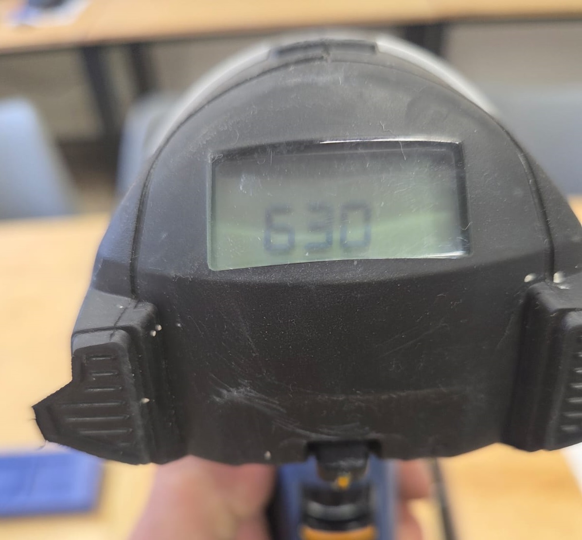
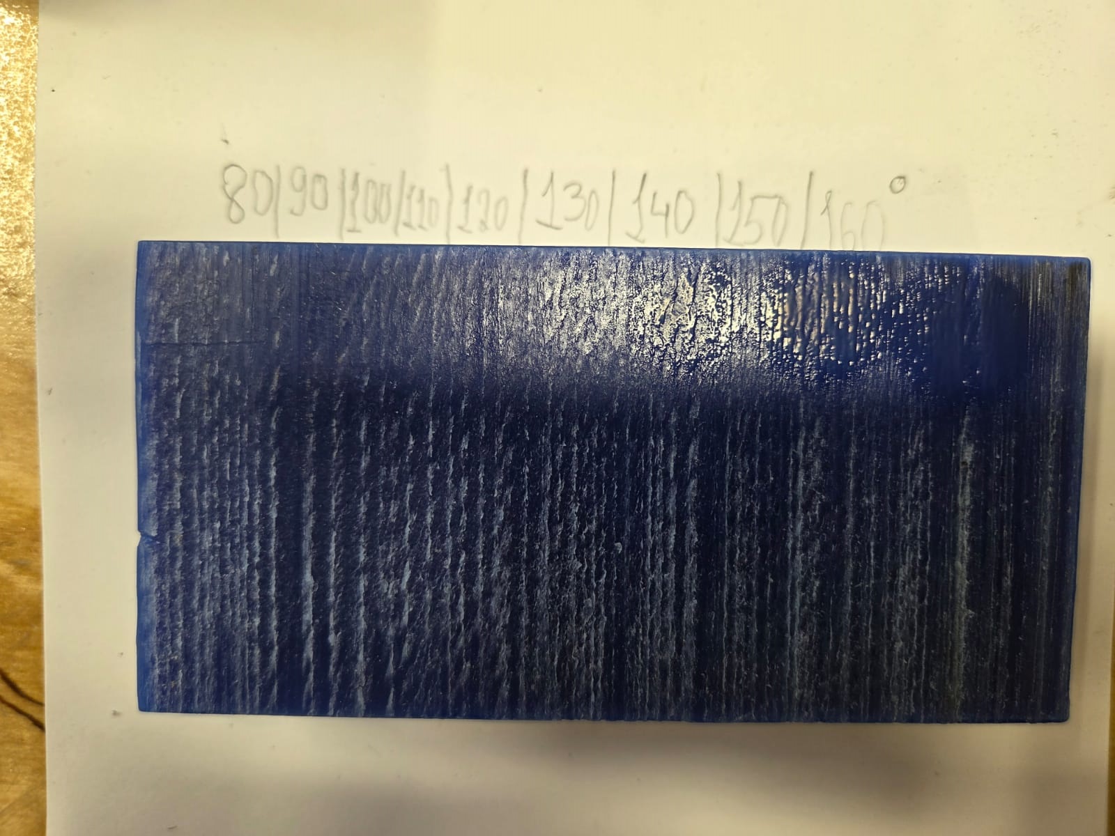
I decided to remove them by heat treatment. I used a heat gun with a temperature range of min 80°C to max 630°C.
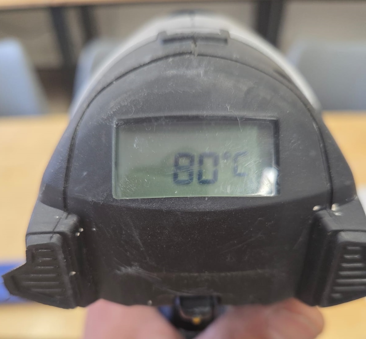
I tested it on the back side of my wax mold. During the test I gradually increased the temperature, starting at 80°C and slowly going up. Reaching 110°C gave me a good result — it did not damage my mold and removed the fibers.
I began bringing it to a finished state, ready for casting. The final result was very good and I was pleased with it.
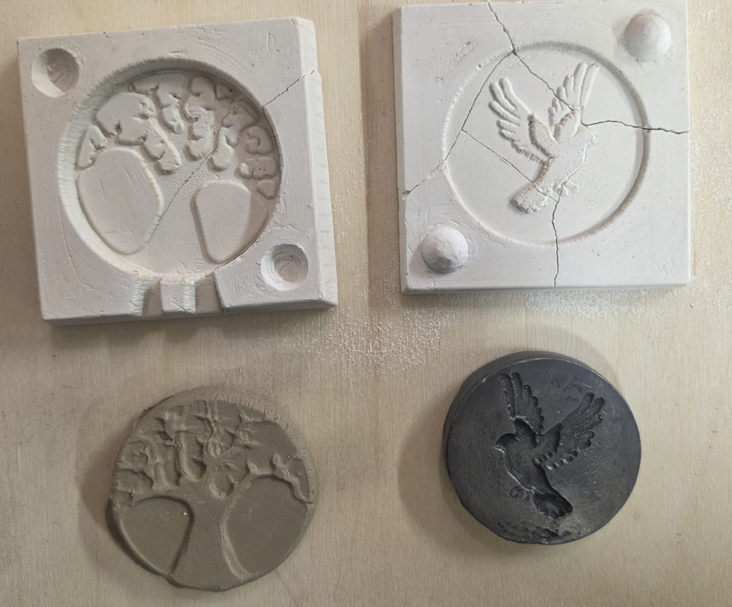
Gypsum Casting Process
Since I had gained experience working with plaster during the group assignment, I began casting with plaster (Plaster of Paris — Safety Data Sheet). I needed plaster, water, and metal clips.
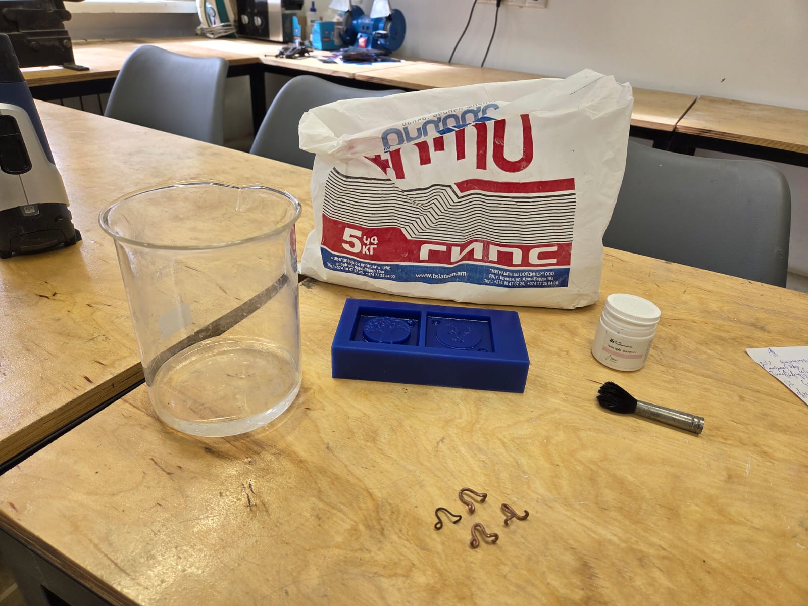
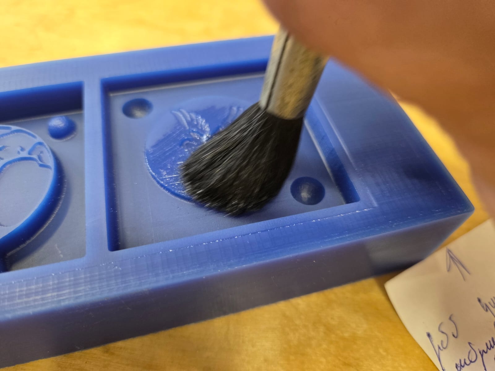
Casting starts by coating the mold surface with a release agent — vaseline.
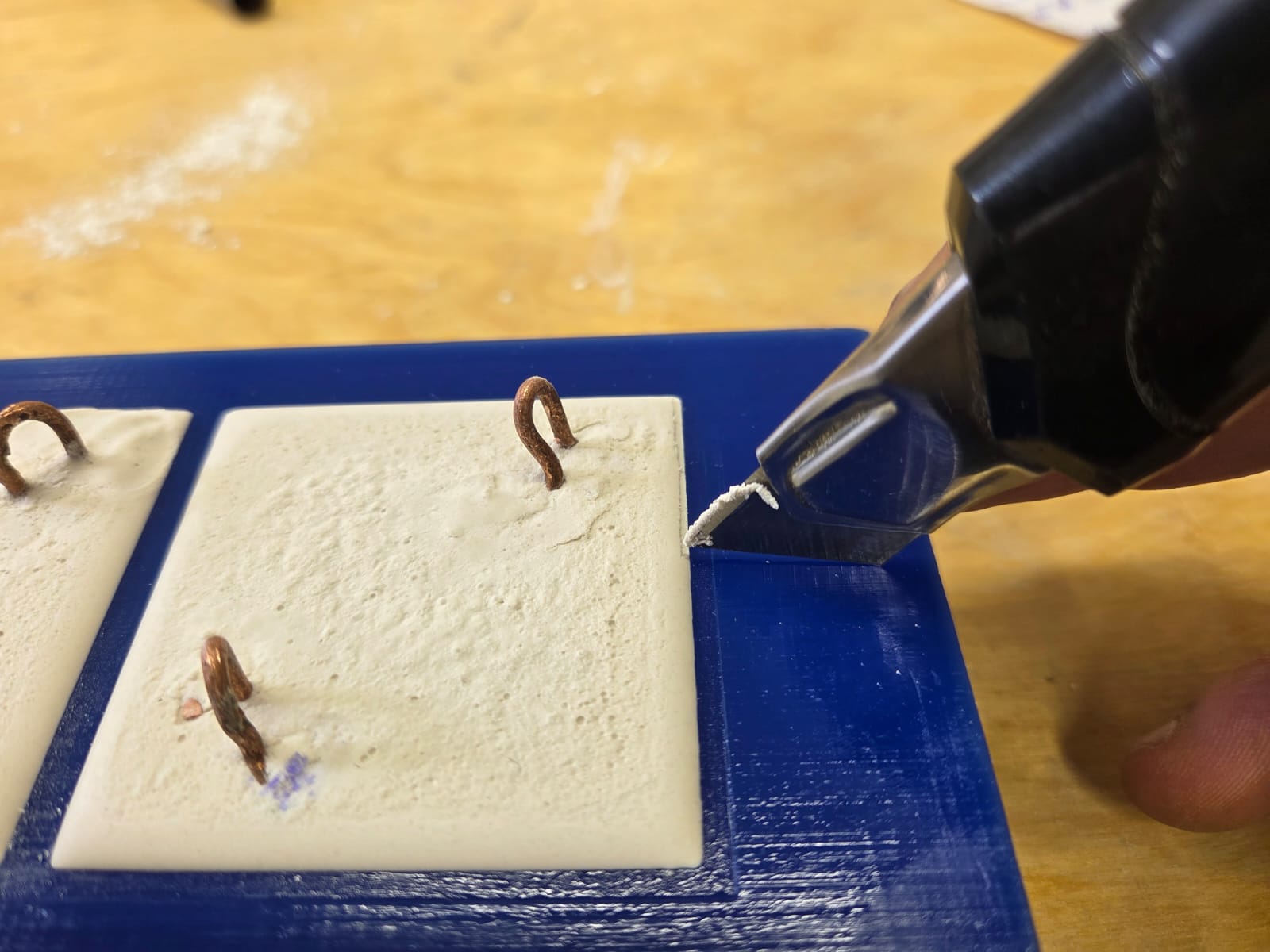
After applying vaseline, I mixed water and plaster until I had a fluid mass and poured it into the mold, removing air bubbles with vibration. After that I placed metal clips inside. The clips were needed so I could easily remove the cast from the mold after drying.
The experience I had failed during group work had been a lesson — not to rush, to let the plaster fully dry, and then easily separate it from the mold. This way, from my wax mold I was able to obtain a plaster mold.
Since plaster is not a very strong material, I made several copies in case any broke during experiments. The process was so engaging that it felt impossible to stop. With several plaster molds ready, I fully dried them and began the next process.
Lead Casting
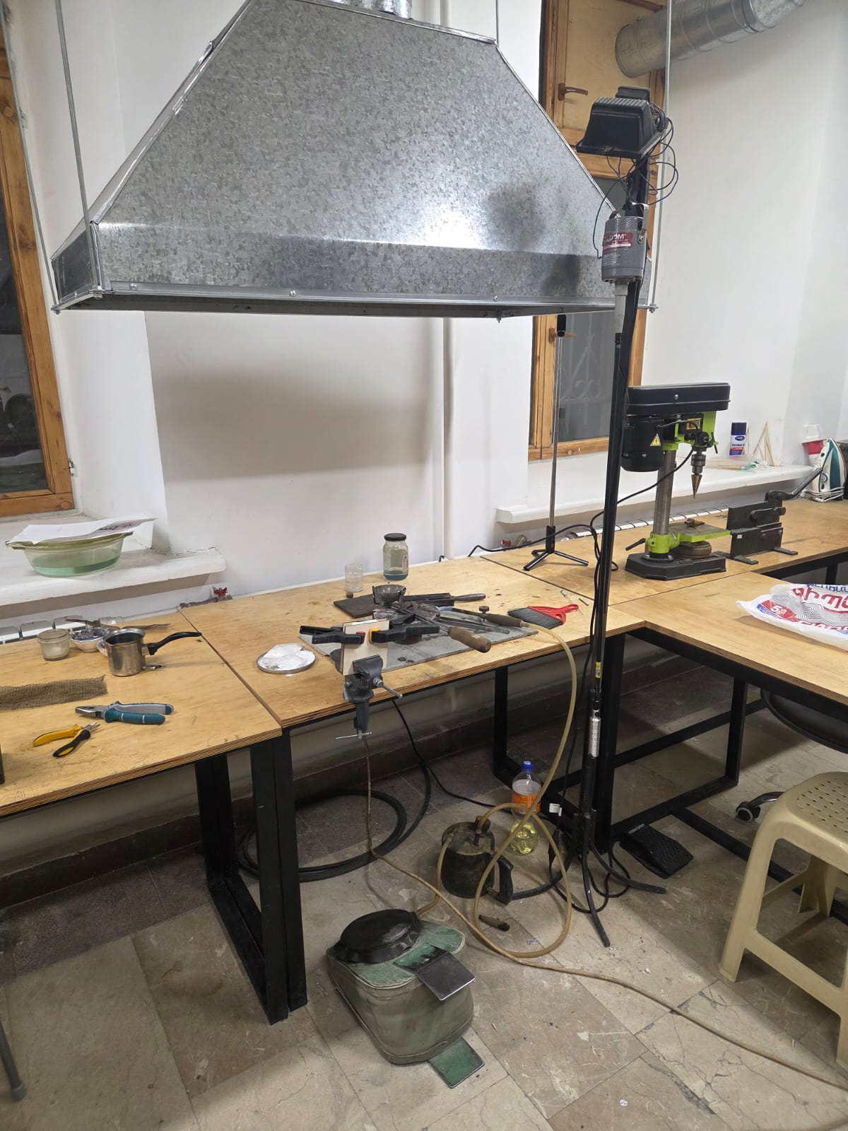
Safety
During casting, it is very important to follow safety rules because lead (Lead Metal — Safety Data Sheet) is subjected to heat treatment, and during that time fumes are released which are dangerous to health. Protective equipment must be worn, including a layered mask that will protect from the emitted heavy gas, and protective goggles must be worn because it may happen that the mold is not completely dried or is cold, since before casting the mold must be heated so that it does not explode. The explosion will occur from the gas produced when cold air and hot metal come into contact, which becomes high pressure and throws back the hot metal. Therefore, it is very important to wear goggles and gloves during the casting process. There must be a well-equipped ventilation system, or if that is not possible, casting should be carried out in an open area outside the building. It is strictly prohibited to perform casting inside a building without a ventilation system.
Thus, in safe and secure conditions it is easier not to make mistakes during casting and to obtain a quality product, and safety rules must be observed.
Source: Casting Safety 101 – Creative Safety Supply
The Casting Process
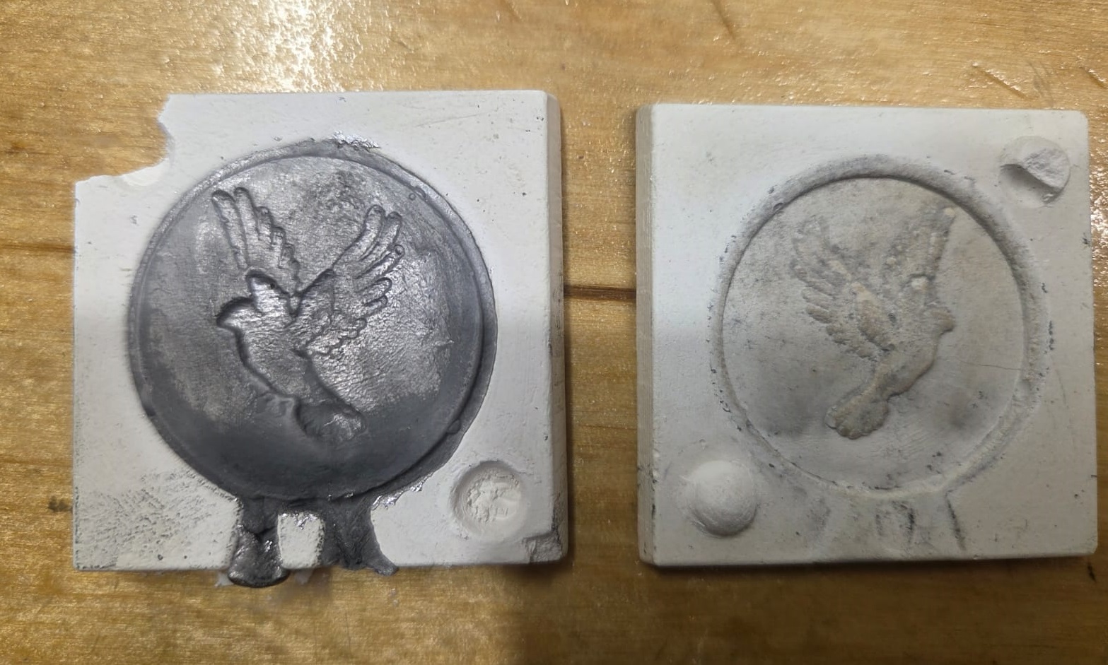
My initial idea was to fill with lead. I connected the two halves of the mold and placed wooden blocks behind them so I could clamp them without damaging the mold. The presence of the wooden pieces was very important so that the mold would not burst from the heat of the molten lead.
With the mold ready for casting, I began the casting process.
I needed lead, a container to melt it in, and most importantly — safety glasses, a mask, and gloves. I successfully completed the casting process and brought the entire workflow to a logical conclusion, obtaining a satisfactory result.
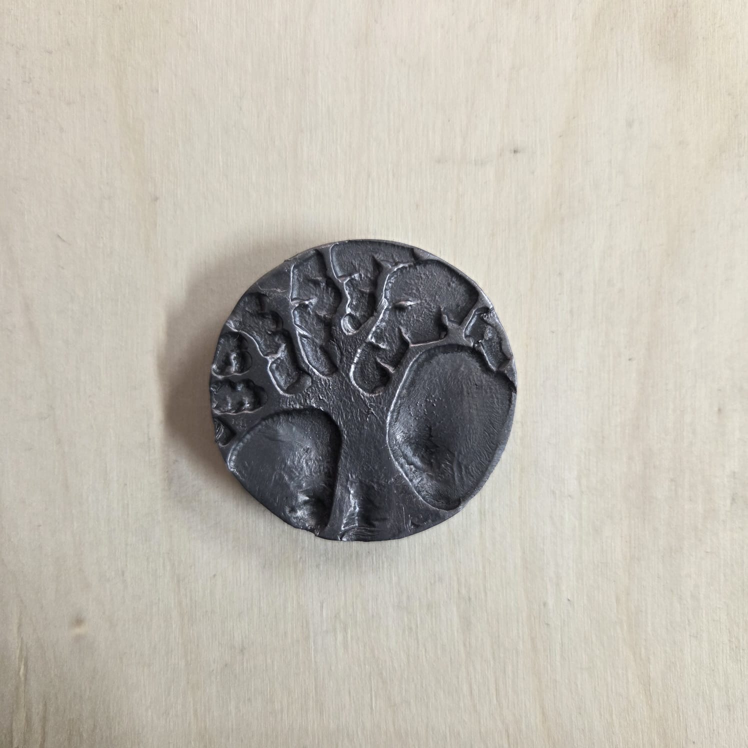
Coin Post-processing
After casting, there were areas that needed finishing. I trimmed the sprues and smoothed out the uneven surfaces.
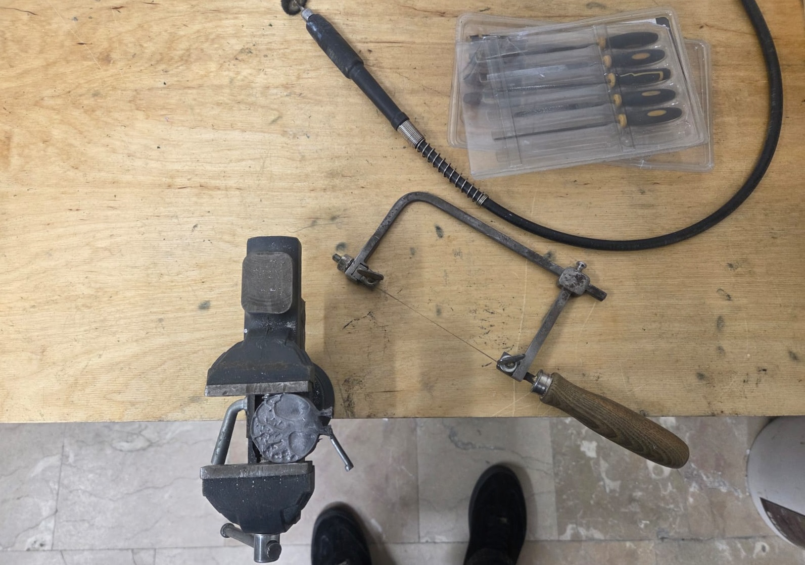
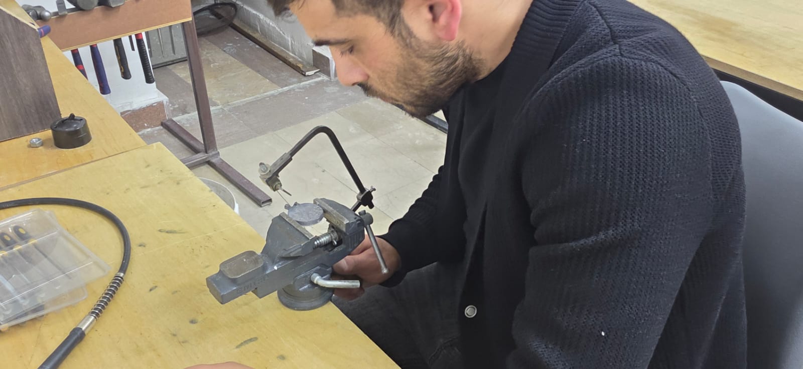
With some polishing I tried to make it look beautiful — and I think it worked out well.
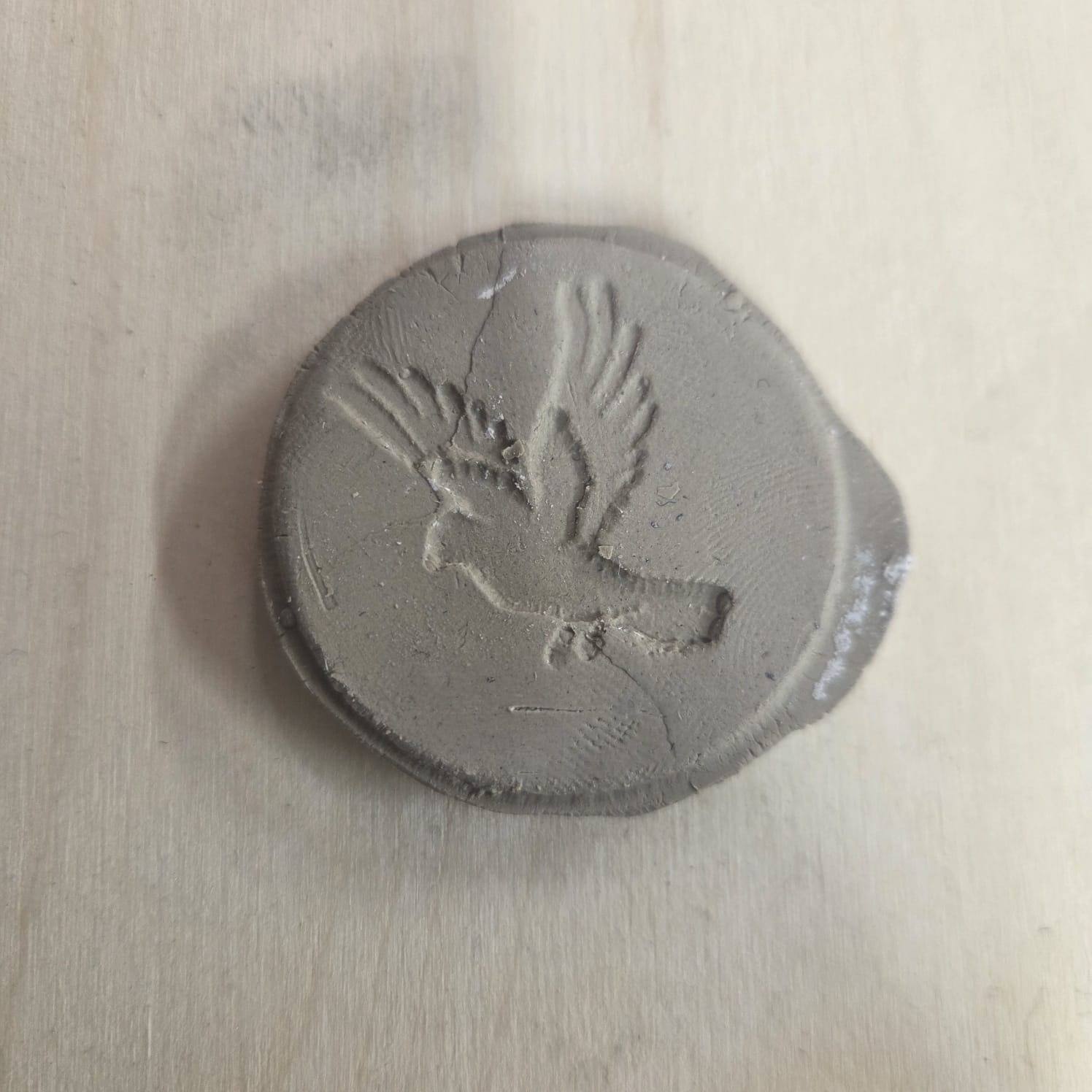
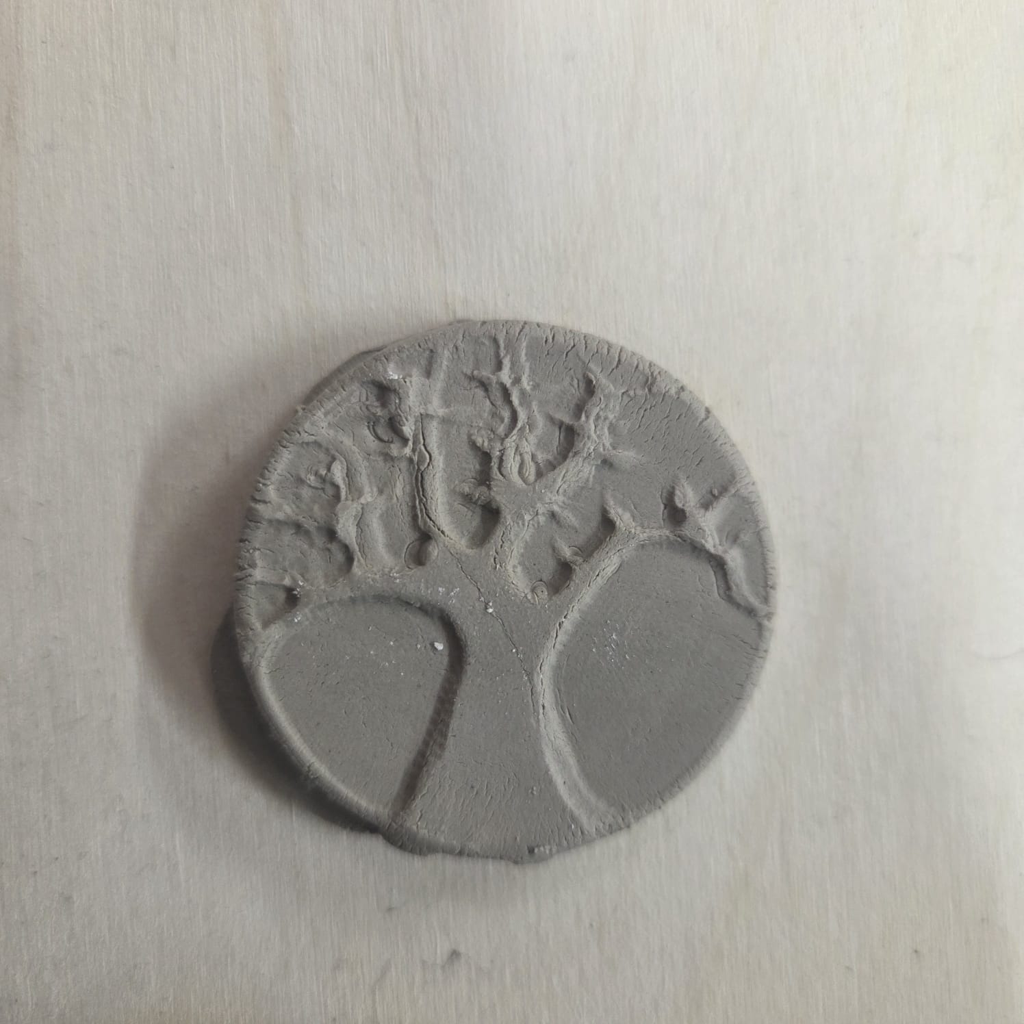
Creating a Medallion by Pressing
I also tried obtaining my medallion from one of the molds using clay (Air-Dry Clay — Material Info), by pressing.
Creating a Silicone Mold
I also decided to create a mold for epoxy resin casting. For this I needed silicone, which consisted of two components — one was the silicone itself, and the other was a curing agent that hardened it.
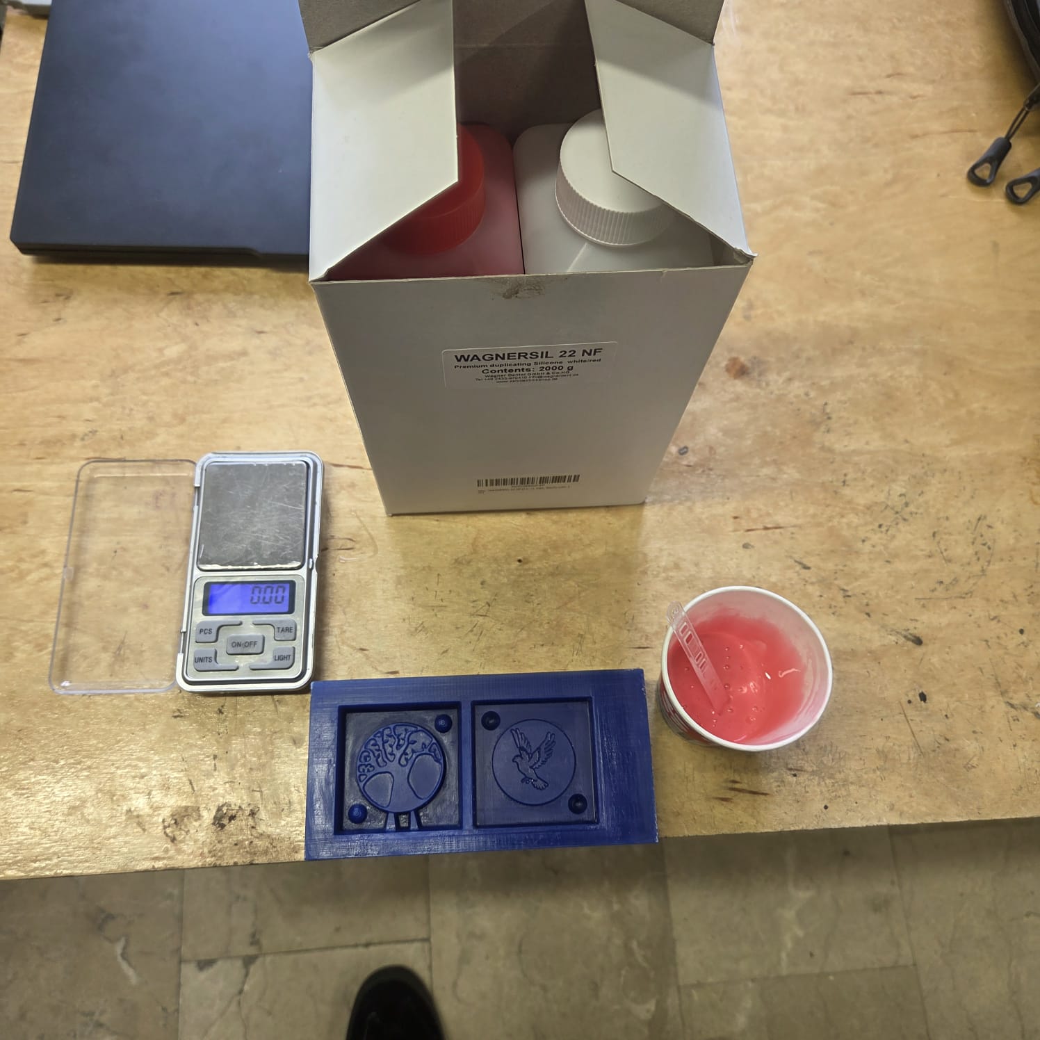
Material Info
Wagnersil 22 NF is a premium duplicating silicone (RTV-2 silicone rubber) used for producing detailed silicone moulds, with a mixing ratio of 1:1 and a hardness of 22 Shore A. It is manufactured for dental, industrial, and craft/hobby mould-making applications.
Manufacturer: Silconic GmbH & Co. KG, Erlenweg 3, 89173 Lonsee, Germany Sold under brand: Wagner Dental GmbH & Co. KG Website: zahntechnikshop.de
Safety Notes
According to the manufacturer, Wagnersil 22 NF is an elastic vulcanisate without reaction heat, non-toxic, odourless, and shrink-free. Even so, standard precautions for working with silicone rubber should be followed:
- Work in a well-ventilated area with fresh air circulation.
- Avoid prolonged skin contact with the unmixed components (A and B); wear gloves while mixing and pouring.
- Weigh components A and B precisely at a 1:1 ratio.
- Keep the work area clean and dry, since moisture can interfere with curing.
- Do not disturb the mould during the curing time (approx. 30 minutes).
Full safety data sheets and instructions for use are available from the manufacturer: Safety data sheets, instructions for use, operating instructions
Result
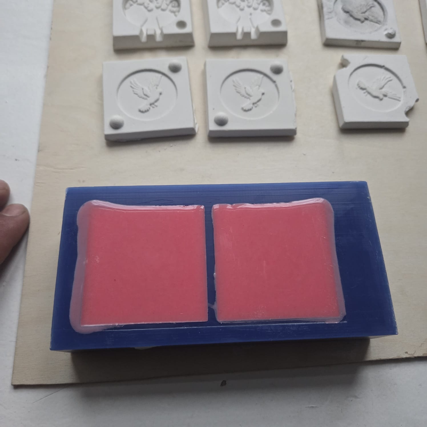
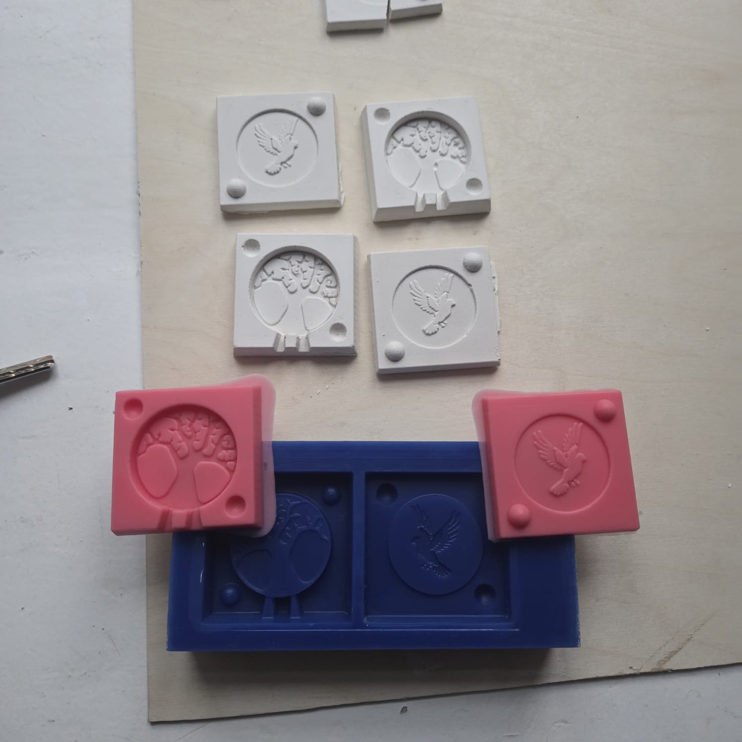
I plan to use the resulting mold for casting epoxy resin.
Conclusion
This week connected directly to my professional background, which made every part of it feel meaningful. The group work taught me patience the hard way — rushing to remove the plaster cast before it had fully dried caused it to break, and that was a lesson I won’t forget.
For the individual project I engraved a double-sided medallion in wax — the Tree of Life and Noah’s dove. Working through FreeCAD’s limitations, draft angles, G-code verification, switching end mills for fine details, casting in lead, trimming, polishing, then trying clay and silicone — each material and each step had its own logic to figure out.
What this week gave me most was the feeling of holding something you made from scratch. That doesn’t get old.