4.Embedded Programming
Group Assignment
Simulation with TinkerCAD and Arduino UNO
Before touching any hardware, we started with a simulation. TinkerCAD lets you wire up virtual components and run code without risking anything, so it made sense to begin there.
We set up an Arduino UNO with a 4-pixel NeoPixel strip. The goal was simple: make each LED show a different color.
The code is based on the Adafruit NeoPixel library examples, adapted for our 4-pixel setup. In setup() we initialize the strip and turn everything off. In loop() we go through each pixel with a for loop and use a switch/case to assign a different color to each one — blue, green, red, yellow.
#include <Adafruit_NeoPixel.h>

#define PIN        4
#define NUMPIXELS  4

Adafruit_NeoPixel strip(NUMPIXELS, PIN, NEO_GRB + NEO_KHZ800);

void setup() {
  strip.begin();
  strip.show();
  strip.setBrightness(50);
}

void loop() {
  for(int i=0; i<NUMPIXELS; i++) {
    switch(i) {
      case 0: strip.setPixelColor(i, strip.Color(0, 0, 255)); break;
      case 1: strip.setPixelColor(i, strip.Color(0, 255, 0)); break;
      case 2: strip.setPixelColor(i, strip.Color(255, 0, 0)); break;
      case 3: strip.setPixelColor(i, strip.Color(255, 255, 0)); break;
    }
  }
  strip.show();
  delay(100);
}
This exercise helped us understand the two main building blocks of an Arduino program: setup() runs once at startup, loop() runs forever. Everything lives inside those two functions.
Programming the XIAO RP2040
Next we moved to real hardware — the Seeed Studio XIAO RP2040, a small but capable board with a built-in RGB LED.
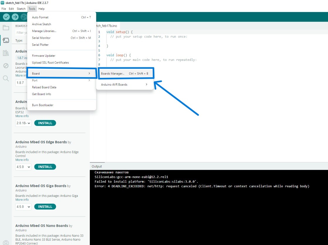
First we installed Arduino IDE and added the RP2040 board library through the Board Manager.
The onboard LED is on pin 12, with a separate power enable pin on pin 11. You have to pull that pin HIGH or the LED doesn’t turn on at all — something worth knowing.
The program cycles through red, green, and blue with 500ms delays between each color. Nothing complicated, but it confirmed the board and toolchain were set up correctly.
#include <Adafruit_NeoPixel.h>

#define PIN_RGB    12
#define PIN_POWER  11
#define NUMPIXELS  1

Adafruit_NeoPixel pixels(NUMPIXELS, PIN_RGB, NEO_GRB + NEO_KHZ800);

void setup() {
  pinMode(PIN_POWER, OUTPUT);
  digitalWrite(PIN_POWER, HIGH);
  pixels.begin();
}

void loop() {
  pixels.clear();

  pixels.setPixelColor(0, pixels.Color(255, 0, 0));
  pixels.show();
  delay(500);

  pixels.setPixelColor(0, pixels.Color(0, 255, 0));
  pixels.show();
  delay(500);

  pixels.setPixelColor(0, pixels.Color(0, 0, 255));
  pixels.show();
  delay(500);
}
STM32F3DISCOVERY Board
The third platform was the STM32F3DISCOVERY. This one has a steeper setup curve than Arduino, but the workflow is more representative of professional embedded development.
Generating code with STM32CubeMX
STM32CubeMX is a graphical tool that generates initialization code and HAL (Hardware Abstraction Layer) files based on your board configuration. You pick your board, set your peripherals, choose a project type (we used CMake), and it generates the skeleton project.
Setting up VS Code
We used VS Code as the editor and compiler. On Linux, you need a few packages first:
sudo apt update
sudo apt install -y gcc-arm-none-eabi openocd make cmake ninja-build
Then we installed the STM32CubeIDE extension pack in VS Code. It picks up the generated project structure automatically. The Cortex-Debug extension adds real-time debugging.
Write your code in main.c, hit run — that’s it.
Summary
Three boards, three different toolchains. TinkerCAD and Arduino are the easiest starting point. The XIAO RP2040 works almost identically in Arduino IDE. STM32 takes more setup but gives you more control and a workflow that’s closer to what’s used in industry.
Tools
- Arduino IDE
- Seeed Studio XIAO RP2040
- USB cable
- Computer
Individual Assignment
During the group work, we explored different microcontrollers and their capabilities. I chose the Seeed Studio XIAO RP2040 because of its compact size and compatibility with Arduino IDE.
I selected the XIAO RP2040 because it is small, easy to use, and suitable for future project integration.
 Photo by author
- Downloaded and installed Arduino IDE.
- Opened the Seeed Studio website.
- Copied the board manager URL.
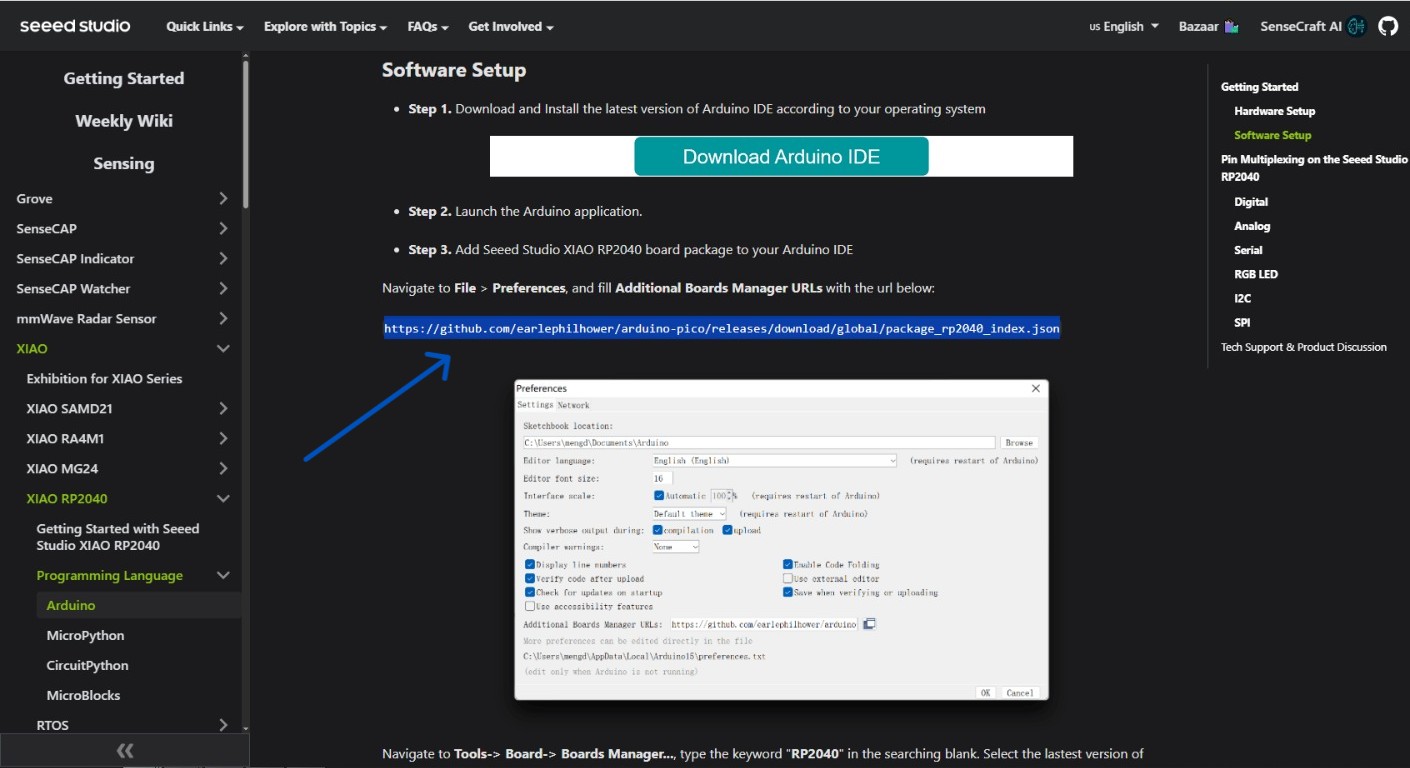
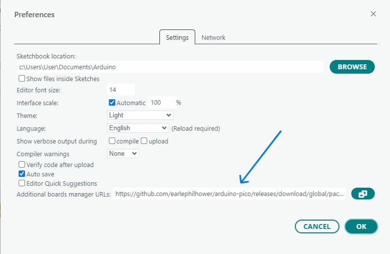
- Added the URL into Arduino IDE preferences.
- Installed the XIAO RP2040 board package.
- Connected the XIAO RP2040 to the computer.
- Selected the correct board from the menu.
- Selected the COM port.
Before making connections, I reviewed the RP2040 pinout diagram to better understand the pin functions and avoid incorrect wiring.
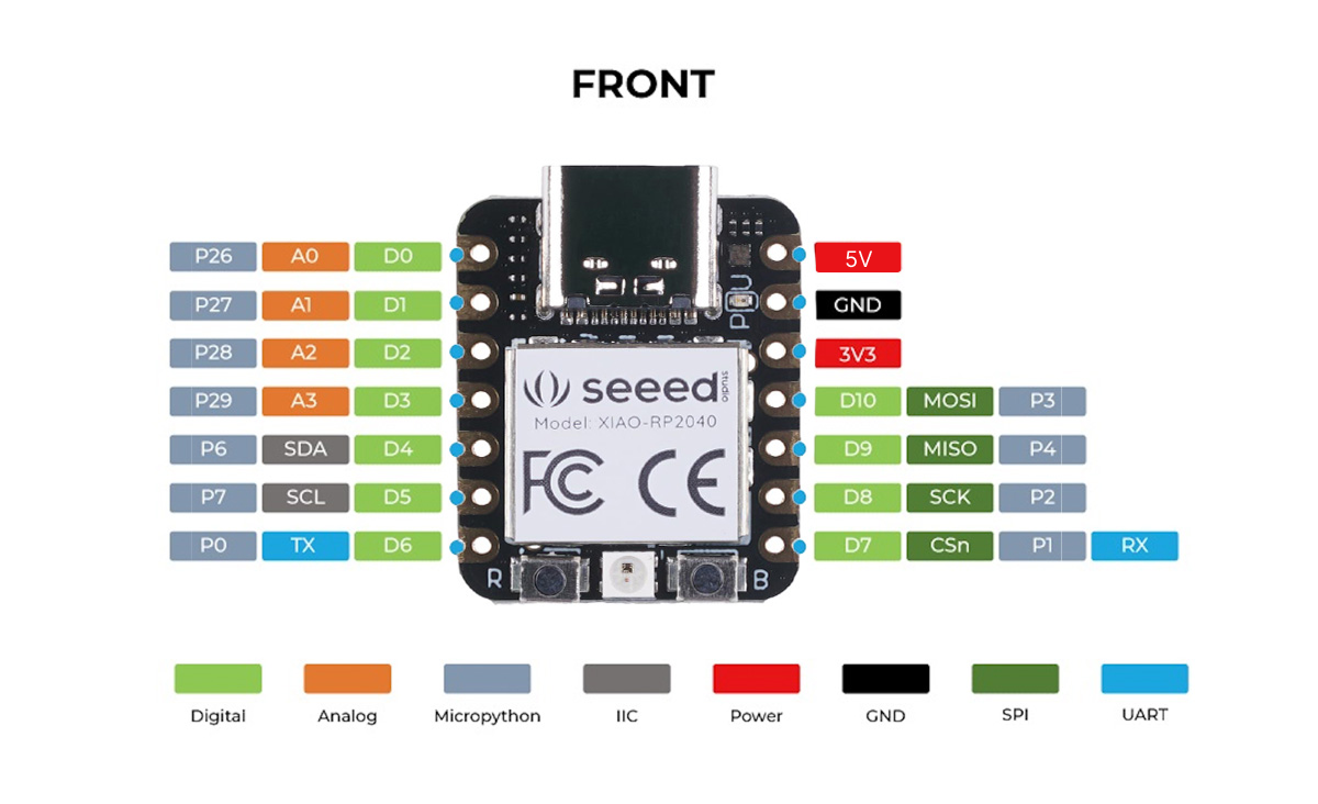 Image source: Seeed Studio XIAO RP2040 Wiki
RP2040 Datasheet
Before writing any code, I opened the official RP2040 datasheet to understand what the chip actually contains.
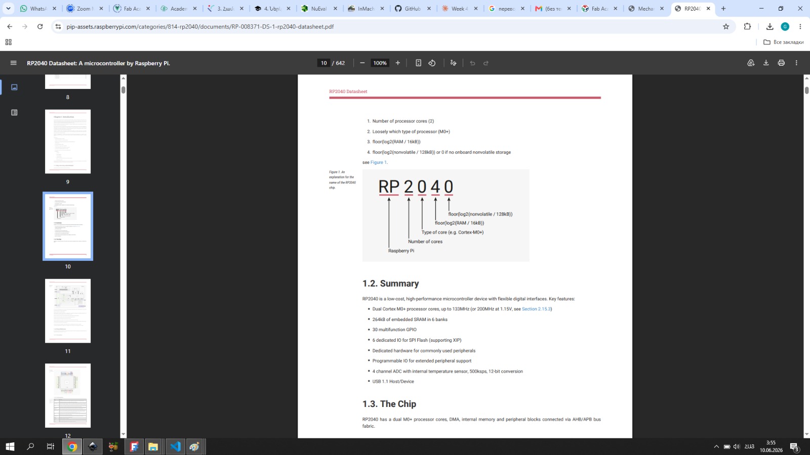
The RP2040 is a dual-core ARM Cortex-M0+ microcontroller made by Raspberry Pi. The name itself is informative: RP stands for Raspberry Pi, 2 means two processor cores, 0 refers to the Cortex-M0+ processor type, and 40 is the number of logical pins.
Key specs from the datasheet:
| Feature | Value |
|---|---|
| Processor | Dual-core ARM Cortex-M0+ |
| Clock speed | Up to 133 MHz |
| SRAM | 264 kB (split into 6 banks) |
| Flash | External only, via QSPI interface |
| GPIO | 30 pins (multifunction) |
| ADC | 12-bit, 4 external inputs + 1 internal temperature sensor |
| Communication | 2× UART, 2× SPI, 2× I2C, USB 1.1 |
| PWM | 16 channels |
| Special | 2× PIO blocks, 8 state machines total |
A few things stood out when reading it.
The RP2040 has no internal flash memory. The program lives on an external chip and is loaded over a QSPI interface. On the XIAO RP2040 board, that flash is already soldered on, so you don’t notice it during use — but the datasheet makes it clear this is separate hardware from the chip itself.
The GPIO pins on the XIAO RP2040 require a power enable pin to activate certain hardware, including the onboard RGB LED. In the datasheet, this is described as a controlled power rail to the LED circuit. In practice, pin 11 (PIN_POWER) must be pulled HIGH before the LED responds at all. I ran into this directly — the LED simply didn’t light up until I added digitalWrite(PIN_POWER, HIGH) to setup(). Without the datasheet, that would have been very hard to debug.
pinMode(PIN_POWER, OUTPUT);
digitalWrite(PIN_POWER, HIGH);  // required — without this, the RGB LED won't turn on
The ADC is 12-bit, meaning it divides the 0–3.3V input range into 4096 discrete steps. This is directly relevant to my final project, where I need to read analog output from a CO₂ sensor. Understanding the ADC resolution from the datasheet helps me know how precisely I can measure the sensor voltage.
The PIO (Programmable I/O) system was something I hadn’t seen before. It’s a mini-processor inside the chip that handles timing-critical communication independently from the main cores. The Adafruit NeoPixel library uses PIO under the hood to generate the precise signal timing that WS2812 LEDs require — which is why the library works so reliably on this board.
The chip also supports Serial Wire Debug (SWD), which allows stepping through code and inspecting memory directly on the hardware. Useful to know for future debugging beyond what the Serial Monitor can show.
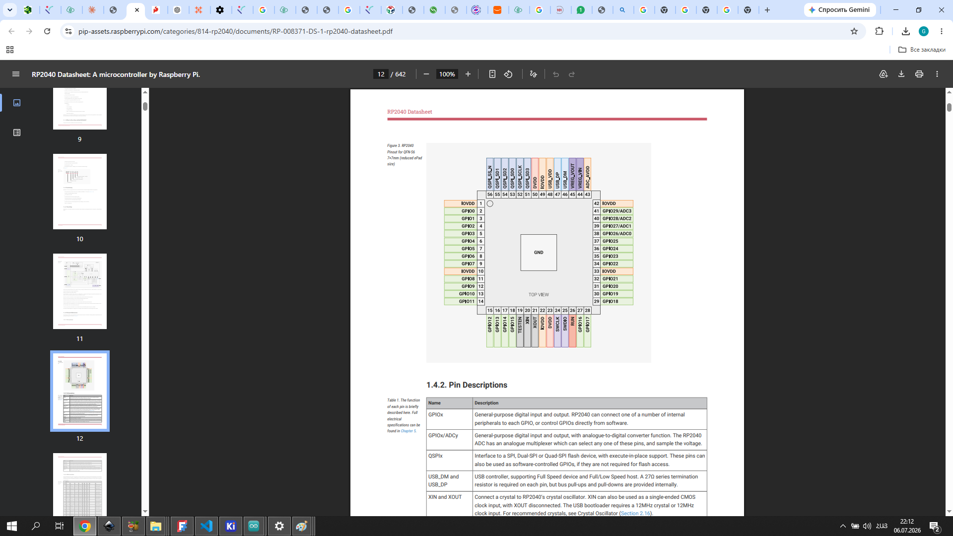
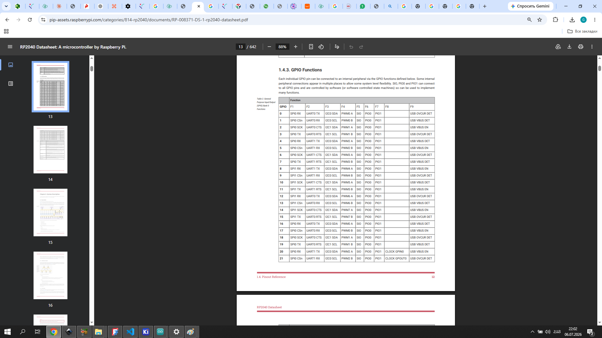
The official RP2040 datasheet (Section 1.4.1) includes a complete pin locations diagram showing all 56 pins of the QFN-56 package:
The GPIO functions table (Section 1.4.3) shows which peripheral can be mapped to each pin:
Programming
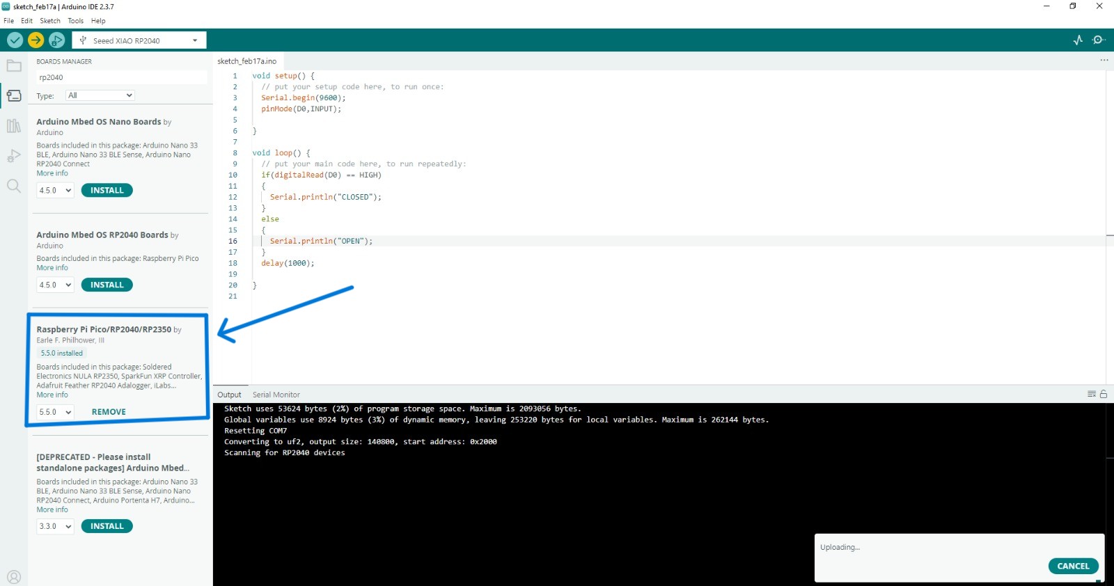
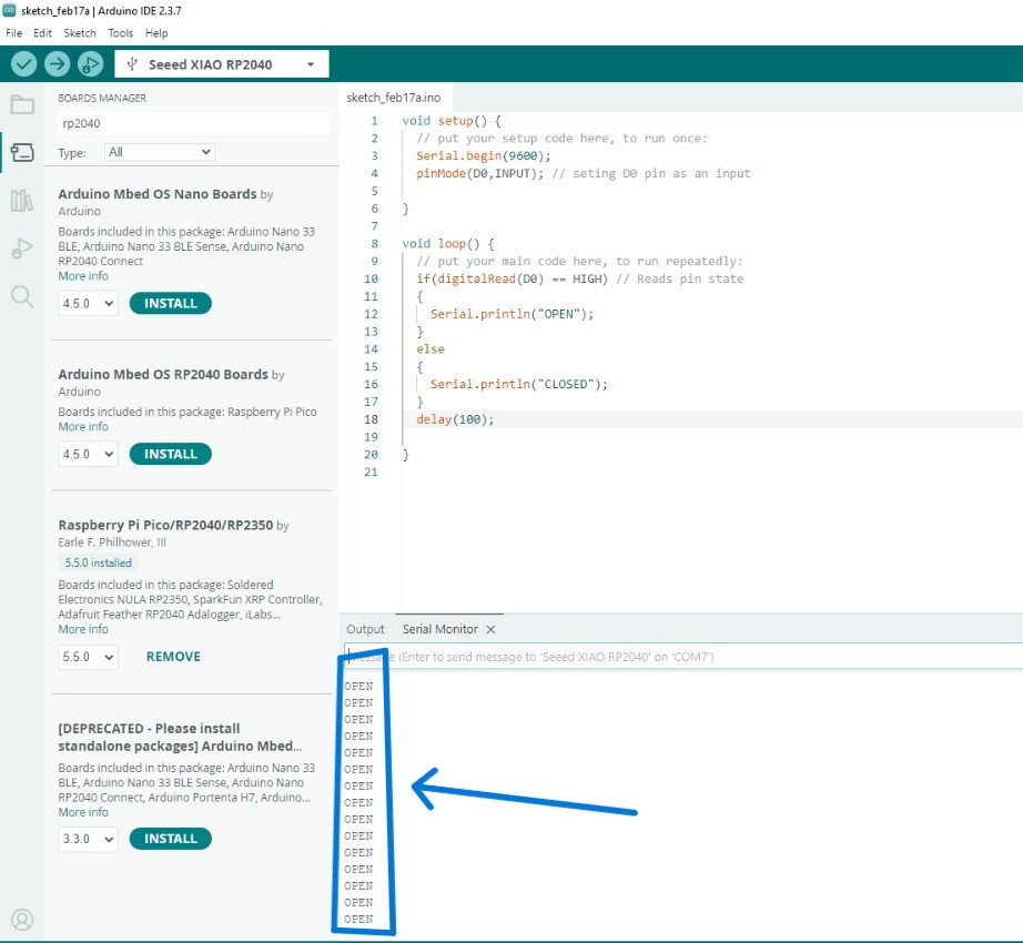
After studying the RP2040 pinout and datasheet, I created a simple program to test input reading from pin D0.
The code initializes serial communication and sets pin D0 as an input. The program continuously reads the digital state of the pin and prints “CLOSED” or “OPEN” in the Serial Monitor depending on the input signal.
Serial.begin(9600)initializes serial communicationpinMode(D0, INPUT)sets pin D0 as inputdigitalRead(D0)reads the pin stateSerial.printlnoutputs the result
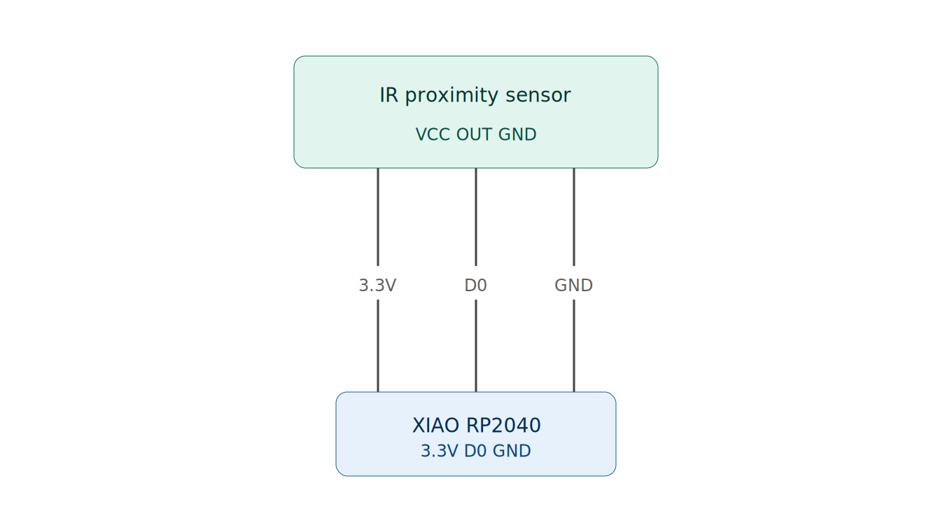
Components Used
| Component | Purpose |
|---|---|
| XIAO RP2040 | Microcontroller |
| IR proximity sensor module | Digital input — detects objects |
| Breadboard | Prototyping platform |
| Jumper wires (M-F) | Connections between sensor and board |
| USB-C cable | Power and programming |
Wiring
The wiring diagram below was drawn using Visualizer / Claude SVG diagram tool — a built-in diagram tool that generates clean SVG wiring illustrations.
I connected the IR proximity sensor to the XIAO RP2040 via the breadboard:
AI Prompt Used
“Write Arduino code for XIAO RP2040 that reads a digital IR proximity sensor connected to pin D0 and prints CLOSED or OPEN to the Serial Monitor depending on the sensor state.”
Code
void setup() {
  pinMode(D0, INPUT);    // set D0 as digital input (sensor signal wire)
  Serial.begin(9600);    // start Serial communication at 9600 baud
}

void loop() {
  if (digitalRead(D0) == HIGH) {  // if sensor outputs HIGH — object detected
    Serial.println("CLOSED");      // print CLOSED to Serial Monitor
  } else {                          // if sensor outputs LOW — no object
    Serial.println("OPEN");        // print OPEN to Serial Monitor
  }
}
Code Screenshot
IR Sensor Demo Video
Serial Output
OPEN
CLOSED
OPEN
This test helped me understand how to read digital input signals and verify hardware connections. The Serial Monitor acts as a wired communication channel between the board and the computer — the microcontroller sends data over USB Serial using the UART protocol, and Arduino IDE receives it in real time. This is the same UART interface listed in the RP2040 datasheet under communication peripherals.
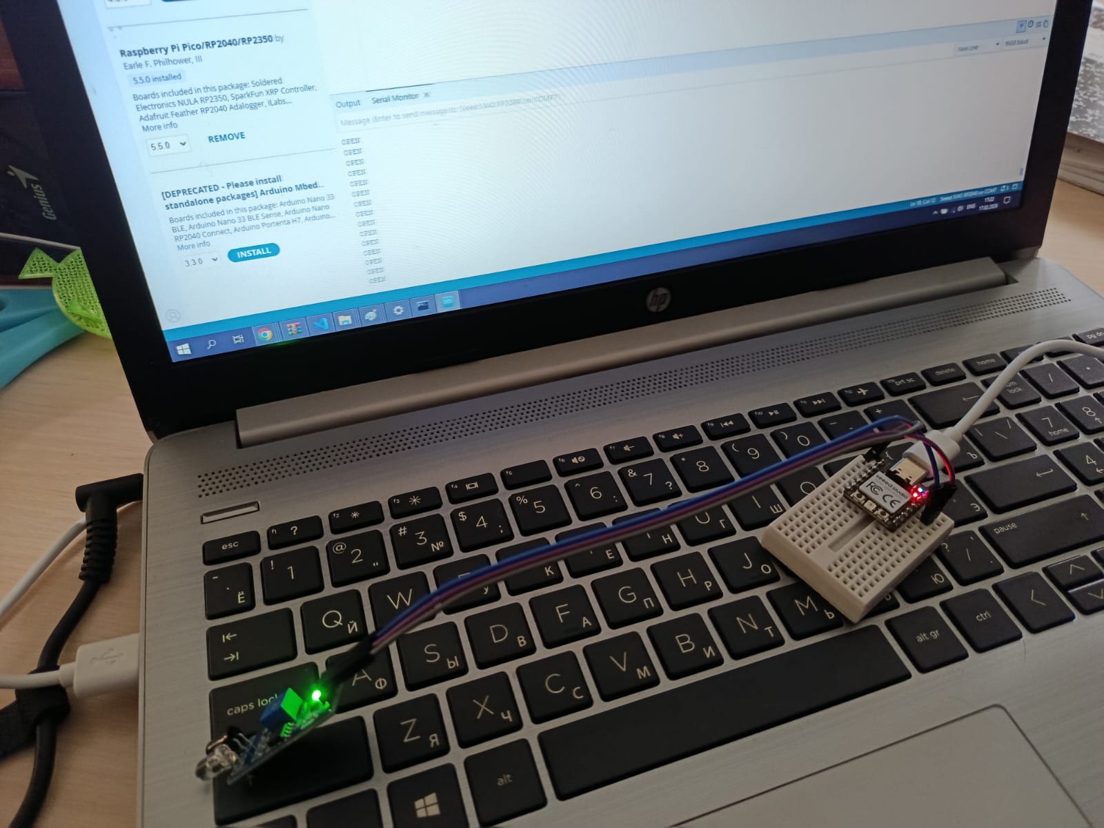
Hero Shot
The XIAO RP2040 running the input reading program, with the Serial Monitor showing live output.
Functions and Variables (Additional Learning)
During this week, I also explored basic programming concepts such as functions and variables in Arduino.
Example Code
#define pin1 17

int distSens = 17;
float var2 = 17.444;
String var3 = "hello Gyumri";
bool var4 = true;

const int var5 = 68;

void myFunc() {
  digitalWrite(pin1, HIGH);
  delay(500);
  digitalWrite(pin1, LOW);
  delay(500);
}

void setup() {
  pinMode(pin1, OUTPUT);
  Serial.begin(9600);
}

void loop() {
  myFunc();
}
Key Concepts
- Function → reusable block of code
- Variables → store data
- setup() → runs once
- loop() → runs continuously
Common Mistakes
#defint pin1 14      // incorrect
char var3 = "text";  // incorrect
bool var4 = tru;     // incorrect
Correct version:
#define pin1 14
String var3 = "text";
bool var4 = true;
Exploring the MQ-7 CO Sensor
While working on embedded programming this week, I had the chance to explore gas sensors directly — something directly relevant to my final project, Vahan.
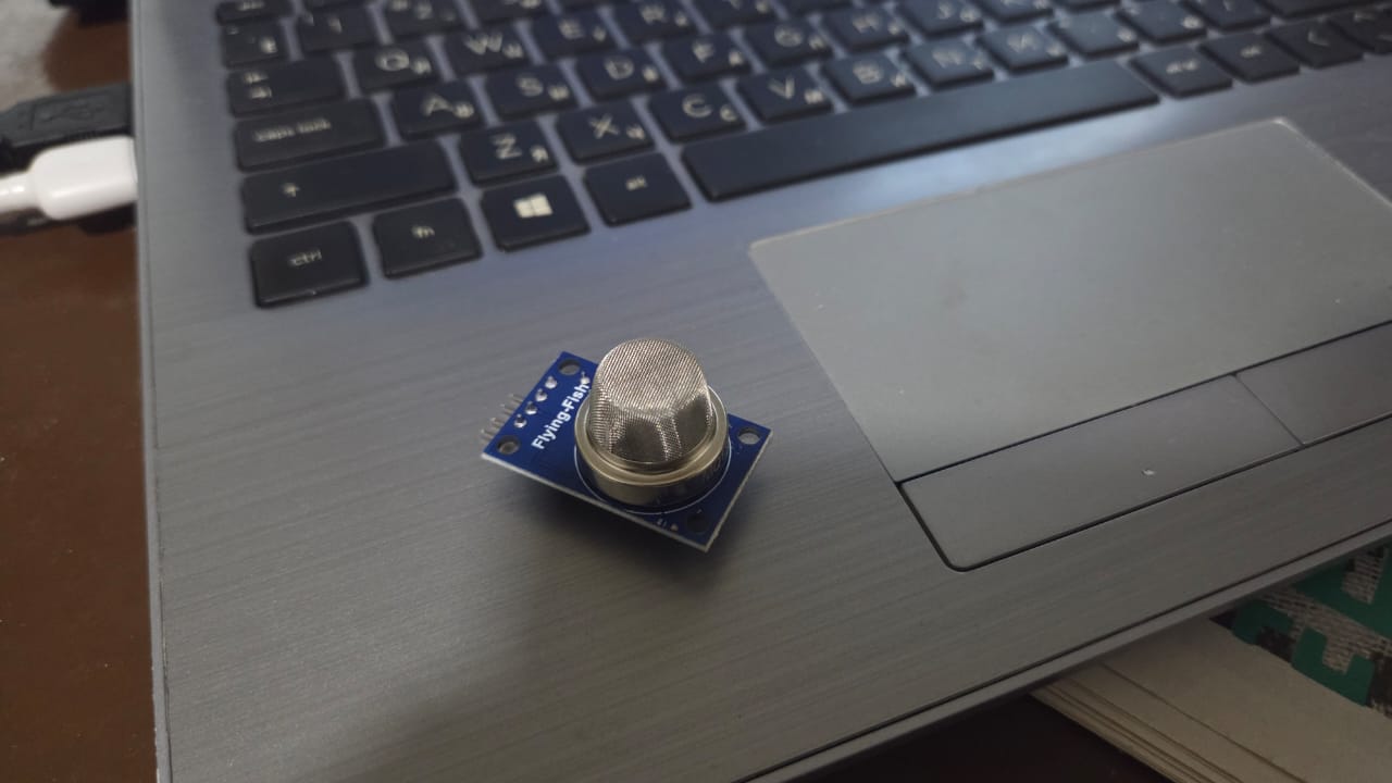
I started with the MQ-135, which was available in the lab. I connected it and watched the Serial Monitor. What I noticed immediately was that it reacted to almost everything — breath, movement, any change in the air around it. The readings jumped constantly. That told me something important: the MQ-135 is a general air quality sensor. It detects NH3, NOx, benzene, alcohol, smoke, and CO₂ all at once, without distinguishing between them. For a safety device in a forge, that’s a problem. If the sensor reacts to everything, you can’t know what it’s actually warning about.
MQ-135 Wiring
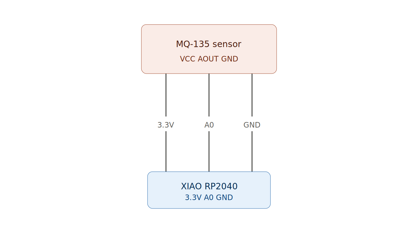 Diagram created using SVG diagram tool (see Week 2 for method)
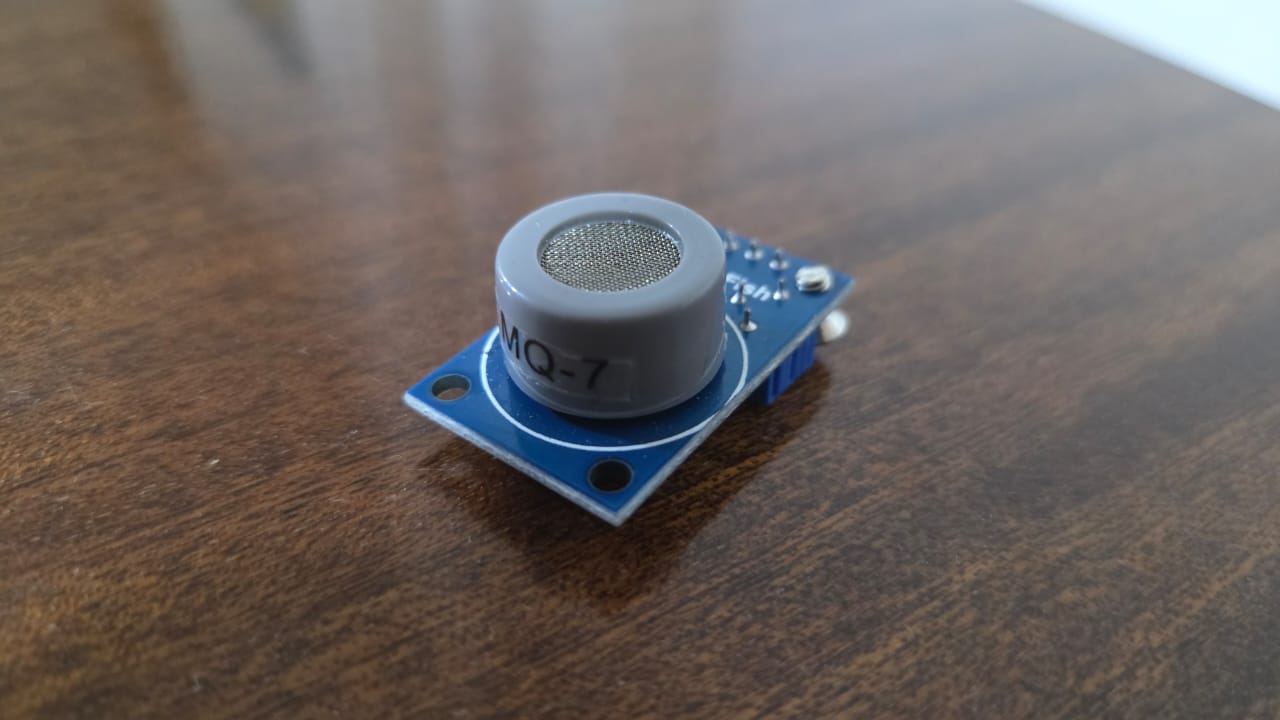
That observation pushed me toward the MQ-7. Rudolf had also pointed me in this direction, and after seeing the MQ-135 behavior myself, I understood why. The MQ-7 is specific — it detects carbon monoxide (CO), which is the primary danger in forge environments, produced by incomplete combustion of coal, coke, and gas.
What the Datasheet Says
The MQ-7 uses SnO₂ (tin dioxide) as its sensing material. In clean air, SnO₂ has high resistance. When CO molecules contact the surface, resistance drops — and that drop is what we measure. The analog output voltage rises as CO concentration increases, so a higher reading means more CO in the air.
The XIAO RP2040’s ADC is 12-bit, which means it divides the 0–3.3V input range into 4096 steps (0–4095). This matters because any code written for Arduino UNO — which uses a 10-bit ADC (0–1023) — needs this adjustment. The same physical voltage gives a different number depending on which board you’re reading it on.
AI Prompt Used
“Write Arduino code for XIAO RP2040 that reads an MQ-7 gas sensor on pin A0 and prints both the raw ADC value and the calculated voltage to the Serial Monitor every second.”
The Code
const int MQ135_PIN = A0;  // sensor analog output connected to A0

void setup() {
  Serial.begin(115200);  // start Serial at high baud rate for fast output
  delay(2000);           // wait 2 seconds for sensor to warm up and stabilize
}

void loop() {
  int rawValue = analogRead(MQ135_PIN);          // read 12-bit ADC value (0–4095)
  float voltage = rawValue * (3.3 / 4095.0);     // convert to voltage (0–3.3V)

  Serial.print("Raw: ");
  Serial.print(rawValue);         // print raw ADC reading
  Serial.print(" | Voltage: ");
  Serial.println(voltage);        // print calculated voltage

  delay(1000);  // wait 1 second between readings
}
I used analogRead() to get a number between 0 and 4095 from the sensor. The higher the CO concentration, the higher the number. I set THRESHOLD at 400 as a starting point — in clean air the sensor typically reads somewhere between 200 and 300, so 400 gives a reasonable margin before triggering the alarm. This value will need proper calibration in a real forge environment.
The delay(2000) in setup() gives the sensor time to stabilize after powering on. The first readings without it are unreliable — the sensor needs a moment to warm up before the output means anything.
The if statement is the core logic: if the raw value crosses the threshold, the LED and buzzer turn on. If it drops back below, they turn off. Simple, but enough to validate that the sensor, the board, and the output devices are all communicating correctly.