2.Computer-Aided Design
This week I seriously sat down with three programs for the first time: Inkscape, GIMP, and FreeCAD. The goal was to visualize my final project idea — a Smart Workshop CO₂ monitoring system that tracks air quality in a workshop and automatically responds to dangerous levels.
Honestly, I don’t have all the components yet, and the final design will probably change a lot. But that’s exactly why I did this now — to have at least a rough picture of what I’m building before starting with the actual hardware.
2D Vector Design — Inkscape
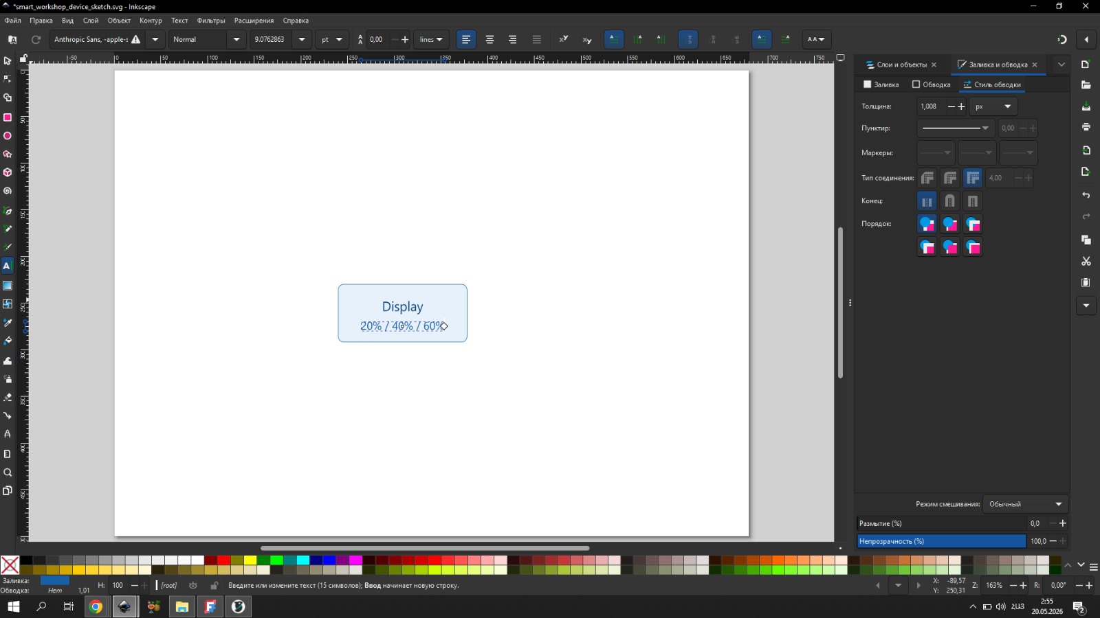
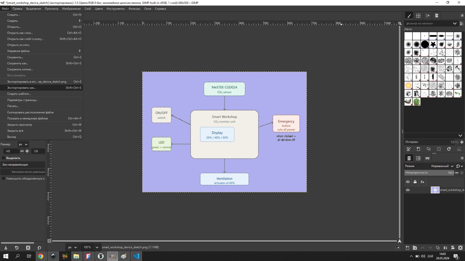
Inkscape isn’t a completely new program for me, but until now I had only done simple things with it. This week I drew a block diagram of the Smart Workshop system, showing all the components and their connections.
The idea is that the CO₂ sensor constantly measures the air condition, and depending on the level, the system responds differently:
- 20% — everything is normal, LED is green
- 40% — a sound signal goes off once, LED changes color
- 50% — strong alarm, LED turns red
- 60% — all safety functions activate, the switch opens, ventilation turns on
The components I drew in the diagram:
- MeSTEK CGD02A — CO₂ sensor, at the top
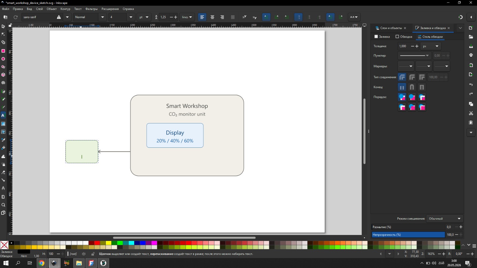
- Smart Workshop unit — main enclosure with a display
- ON/OFF switch — left side
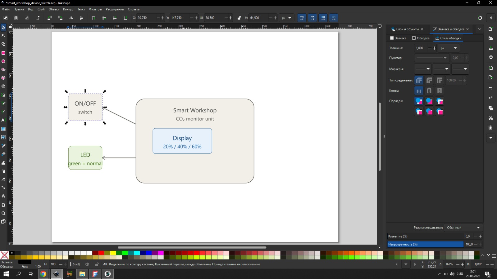
- LED indicator — green = normal

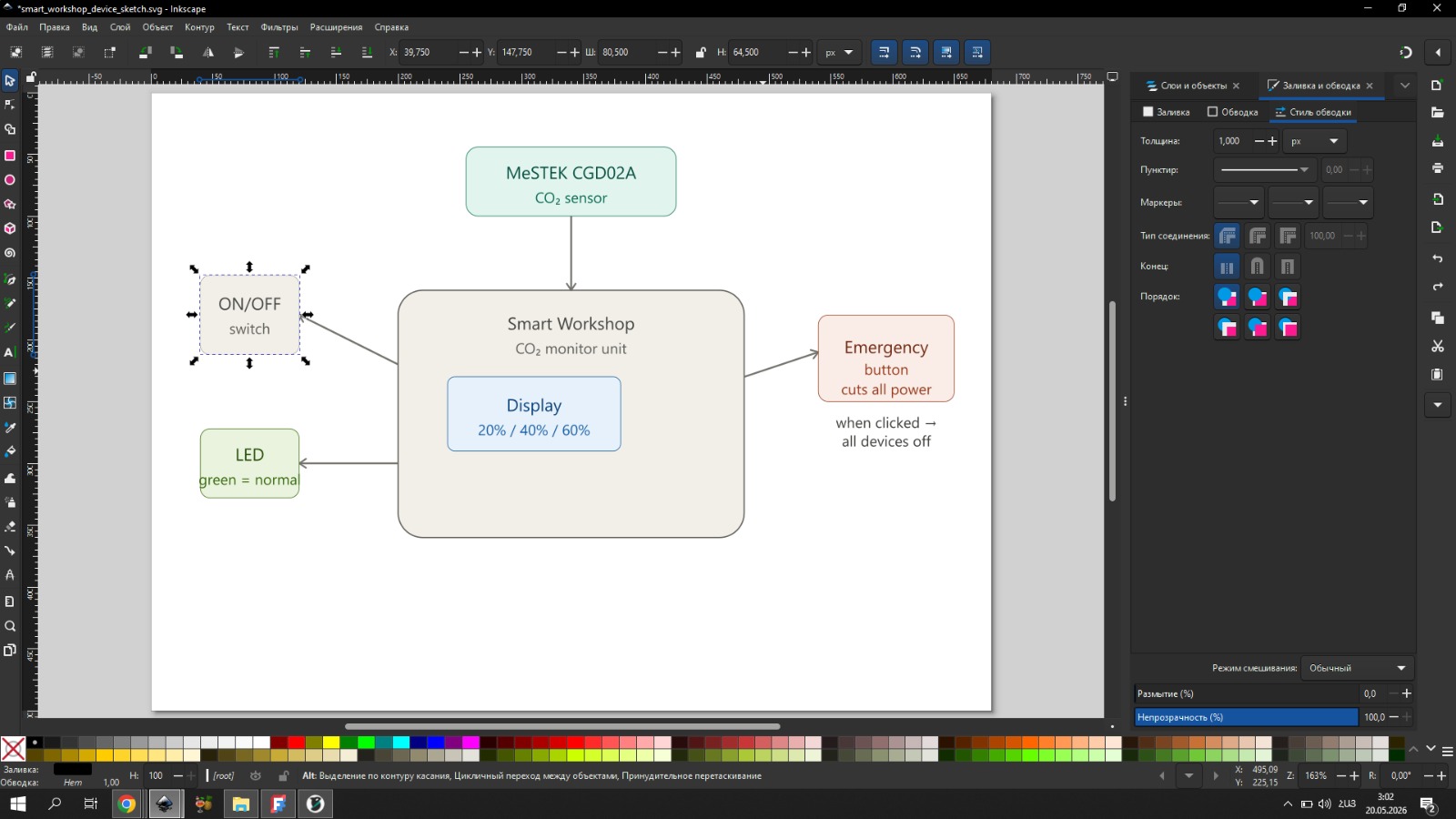
- Emergency button — right side, cuts all devices when pressed
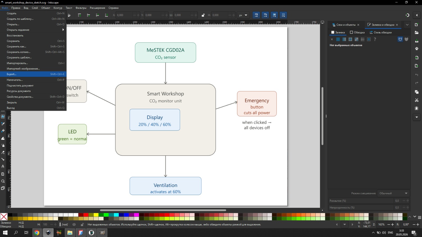
- Ventilation — bottom, activates automatically at 60%
Tools I used in Inkscape:
- Rectangle tool (R) — for all the blocks. Used Rx / Ry fields to round the corners
- Text tool (T) — for labels
- Bezier tool (B) — for connecting arrows between components
- Fill and Stroke (Shift+Ctrl+F) — for colors and border thickness
One thing I didn’t know at first — arrow heads don’t appear automatically, you have to add markers manually from the Object menu. It took a little time to find, but after that it was easy.
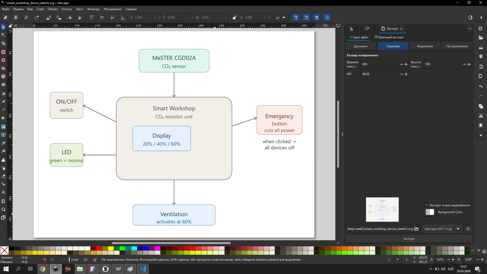
I saved the file as .svg and exported a .png for the website.
Raster Design & Image Compression — GIMP
The main goal of working with GIMP this week was image compression. All images on the Fab Academy website should be as small as possible so the page loads quickly.
Here’s what I did:
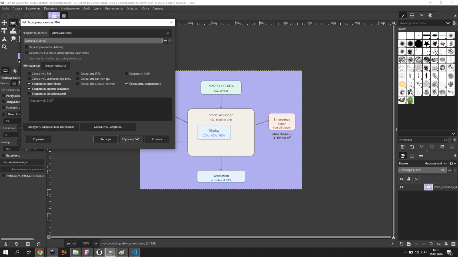
- Opened the PNG exported from Inkscape in GIMP
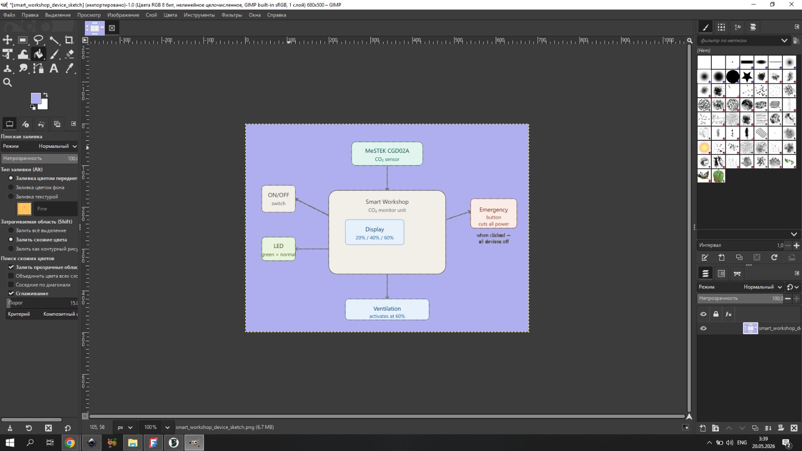
- Went to File → Export As
- Selected PNG format
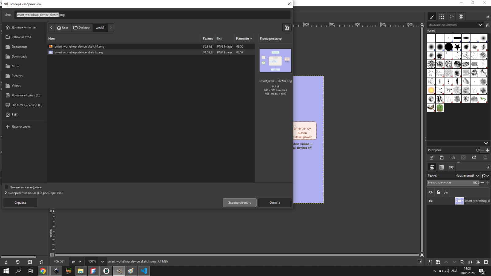
- In the export dialog set Compression (Deflate Compression factor) to 7
- Clicked Export
The result:
| File size | |
|---|---|
| Original PNG | ~947 KB |
| Compressed PNG | ~340 KB |
It’s important to understand the difference — PNG compression doesn’t damage image quality, it just stores the data more efficiently. With JPEG, quality can be lost, but PNG is lossless. When building a website, every MB matters — especially when there are many screenshots in the documentation.
Creative Use of GIMP — Final Project Poster
Beyond compression, I also used GIMP to create a small poster for my final project, Vahan. I took the revised concept sketch from Week 01 and added text directly on top of it using the Text tool (T) — the project name, “Fab Academy 2026,” and a short description of what the device does.
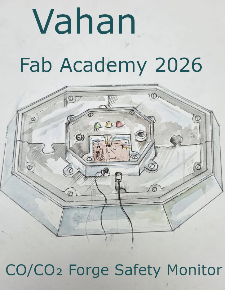
This was a quick way to see how the project could be presented as a single, self-contained image — something I can reuse later for the final project page or a printed handout.
Video Compression — HandBrake
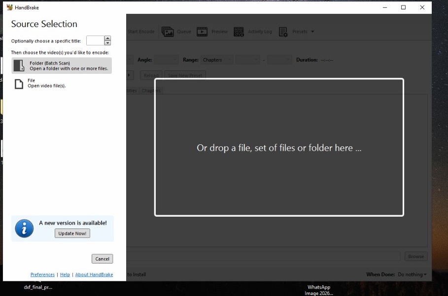
My Fab Academy classmate Mariam told me about this tool, and after looking it up online I found HandBrake — a free, open-source tool created by volunteers, designed to convert video from almost any format. It works on Windows, Mac, and Linux.
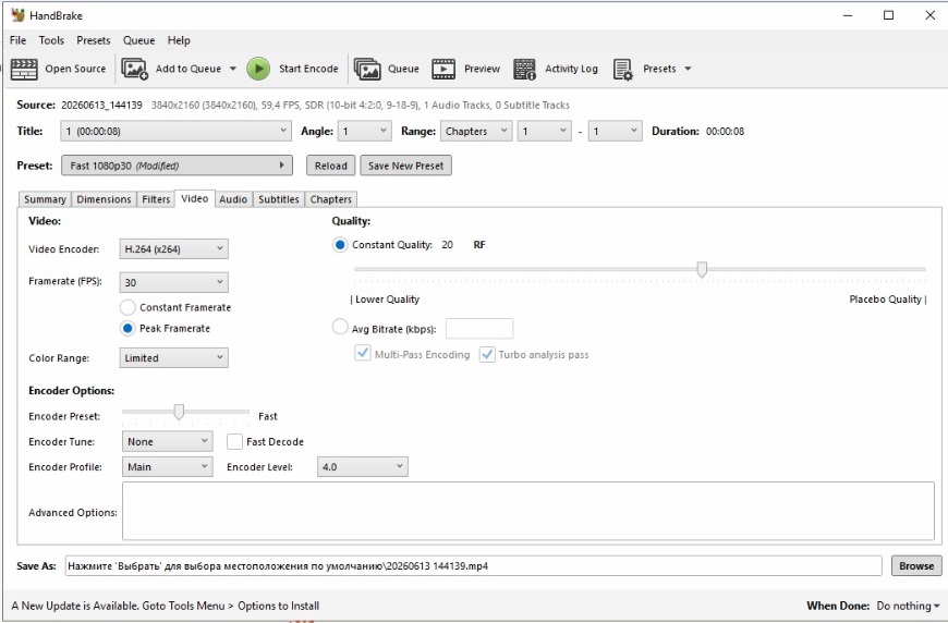
After opening the tool, the Source Selection dialog asks what you want to load — a single file or an entire folder. I chose File and loaded the video.
Then I went to the Video tab and configured the main settings. I set the encoder to H.264 (x264), framerate to 30 FPS, and for quality I chose Constant Quality RF 20. The lower the RF value, the higher the quality — 20 is a good point where the file stays small but quality is visually acceptable.
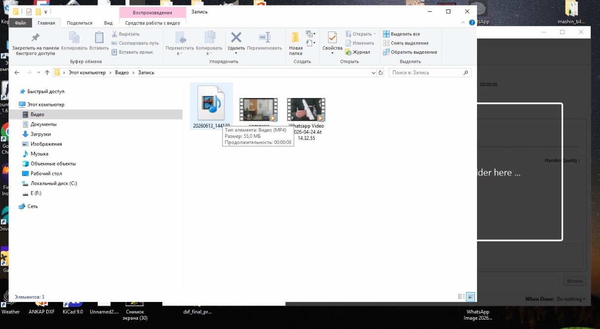
Before encoding I checked the original file size — 55 MB.
I clicked Start Encode and a few seconds later the result was ready. The file became 5.16 MB — more than 10 times smaller, and watching the video the difference was barely noticeable.
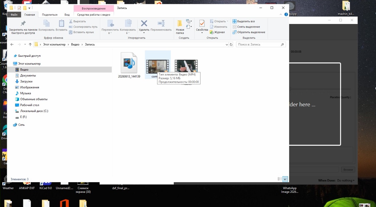
I also tried encoding with a lower RF value to reduce the file size even further, but the quality dropped to an unacceptable level. So I decided to stick with the 5.16 MB result, which for me was a good balance between size and quality.
Image Compression — imagecompressor.com
My instructor Rudolf Igityan recommended using imagecompressor.com to reduce image file sizes.
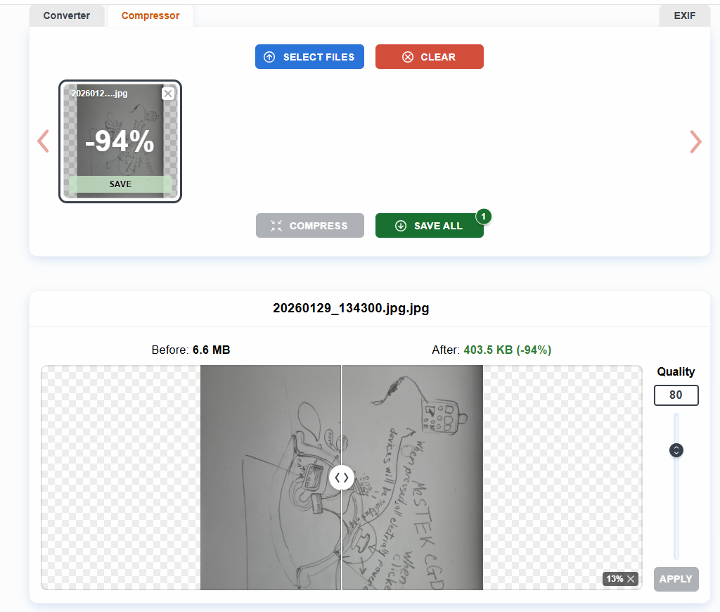
For JPEG files the default target quality is 80, which provides an excellent balance between file size and visual quality for most images. You can adjust this with a slider — higher values preserve more detail but produce larger files, while lower values create smaller files with more visible compression artifacts.
I tried this on one of our images, which was 6.6 MB. With quality 80, the file dropped to 403.5 KB (-94%).
Then I wanted to see what happens if I go lower, so I moved the slider down to 30. The file size dropped to 132.9 KB (-98%).
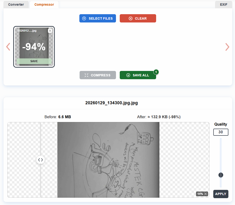
I expected the quality to drop a lot, but the difference was barely noticeable — the drawing stayed clear and no details were lost. After this test, I decided that quality 30 is good enough for the images in my documentation, since the size difference is huge and the visual loss is practically nothing.
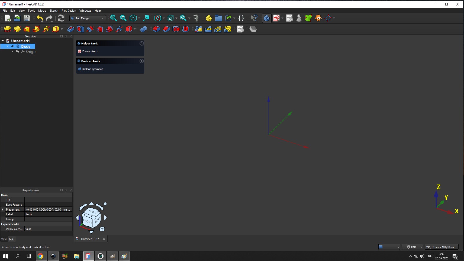
3D Design — FreeCAD
In FreeCAD I modeled a rough version of the Smart Workshop enclosure. The goal was to understand what the device would physically look like and where each component would sit.
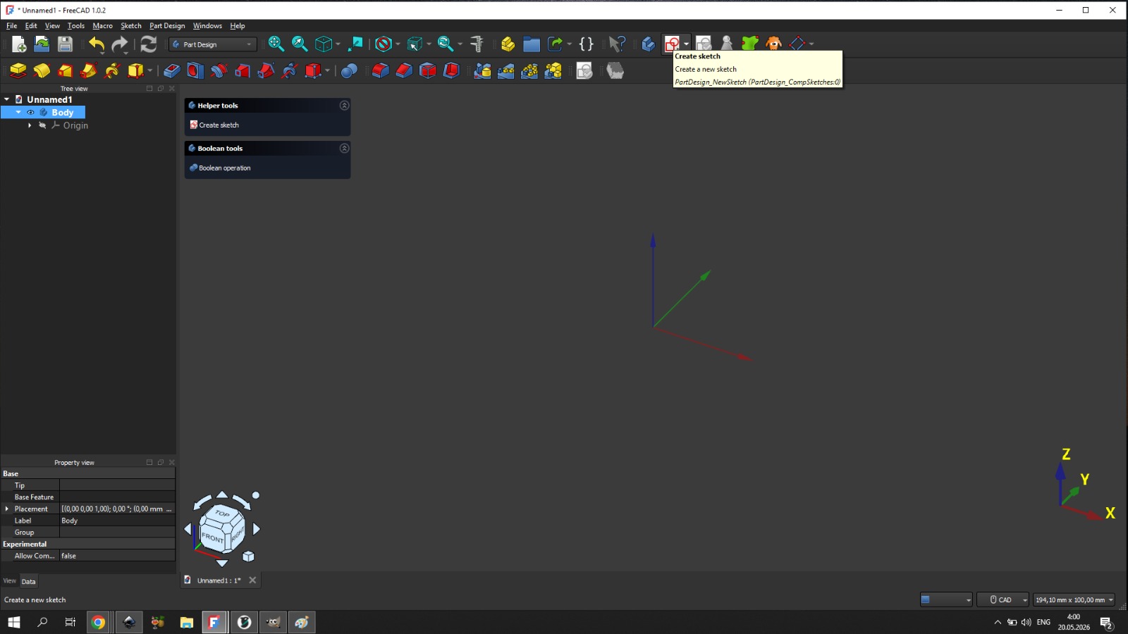
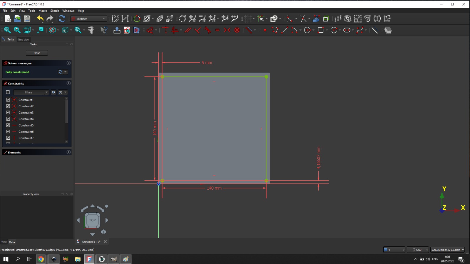
I worked with the Part Design workbench, step by step:
- Part Design → Create Body
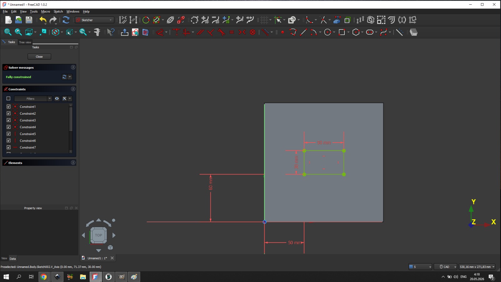
- Create Sketch on the XY plane — drew the outer shape of the enclosure
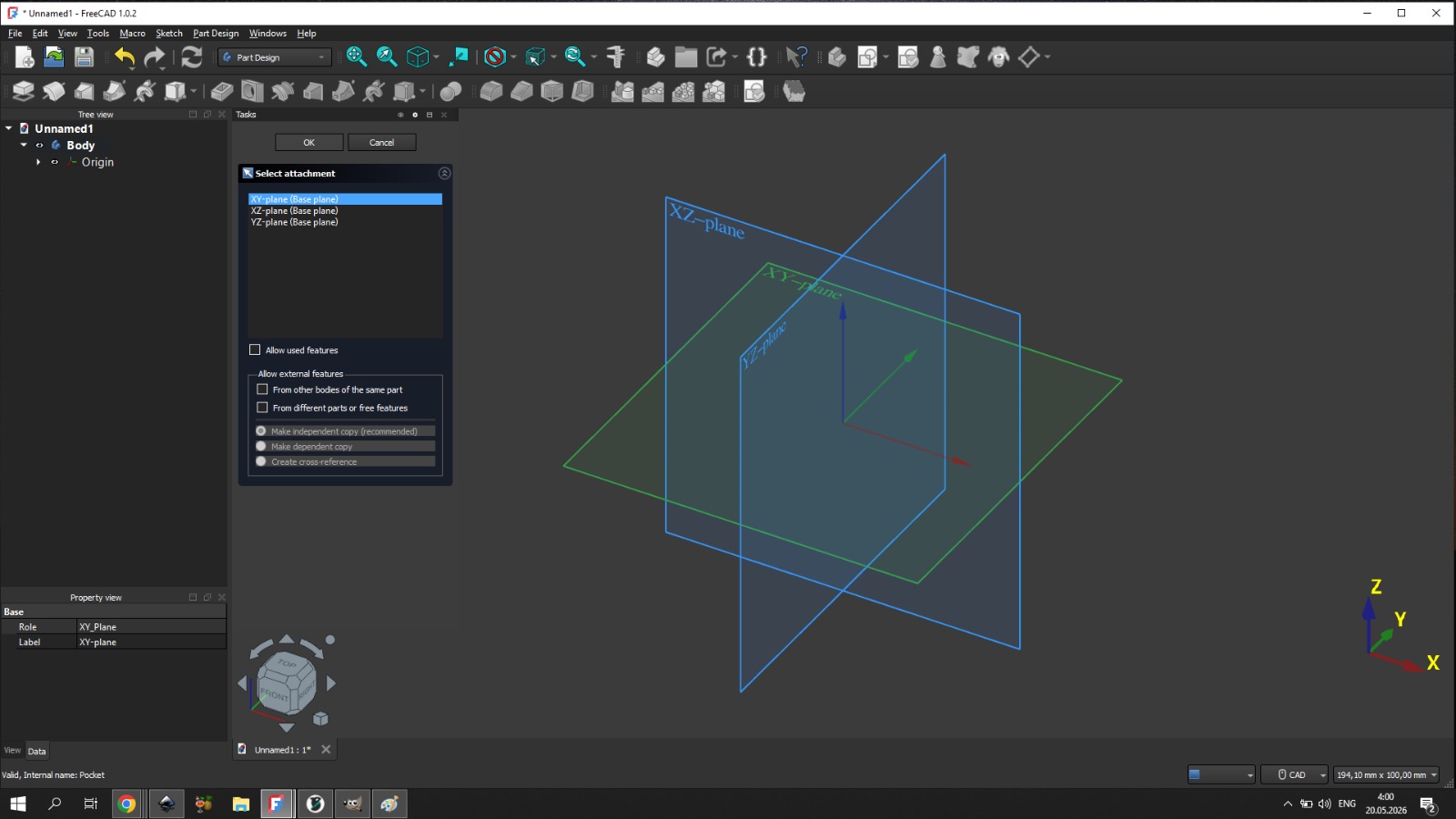
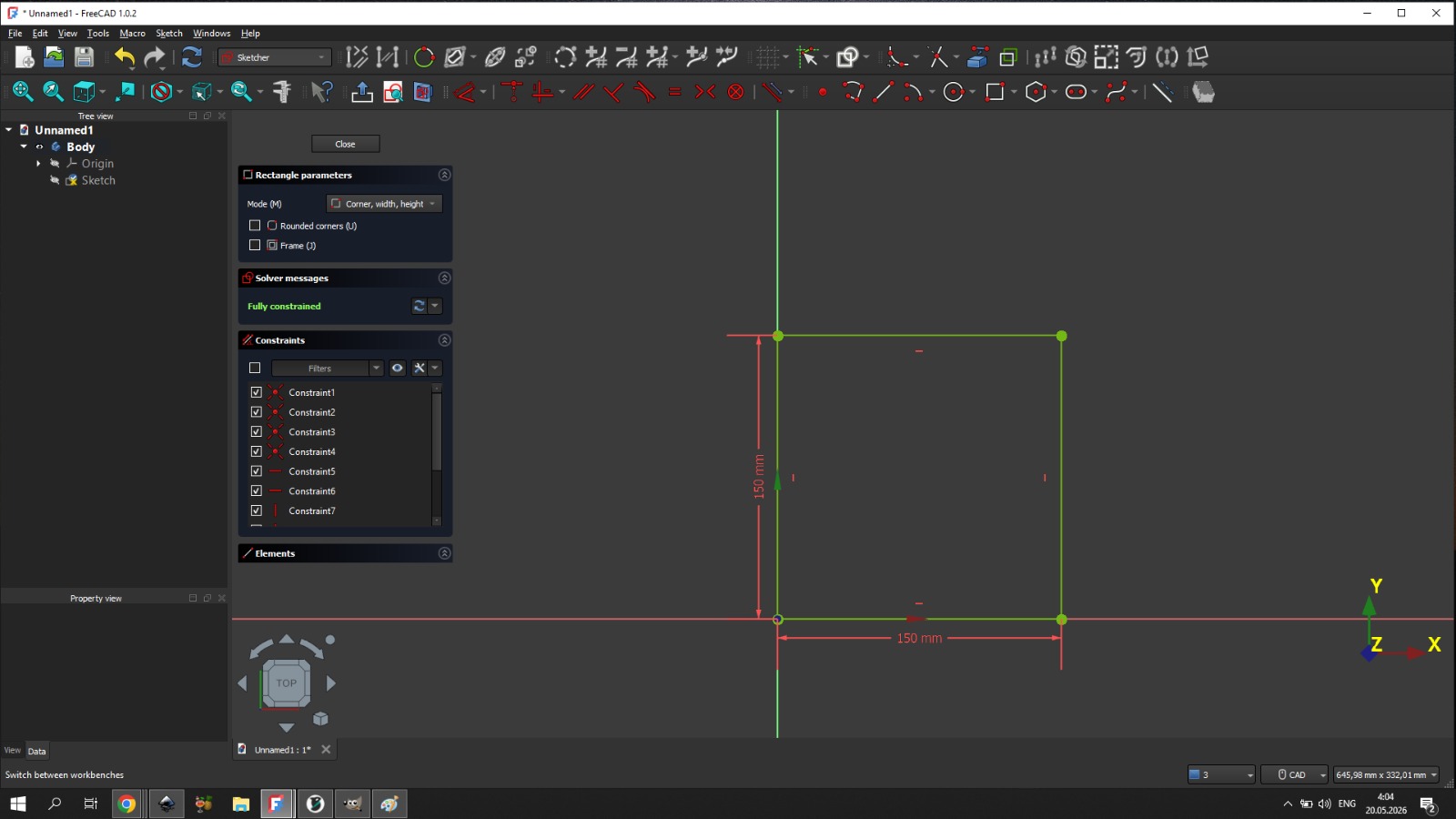
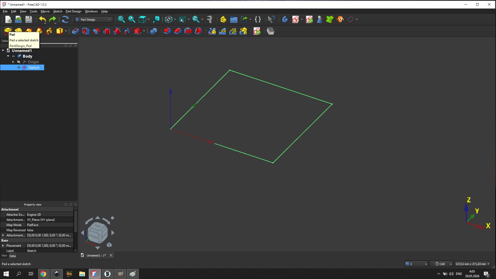
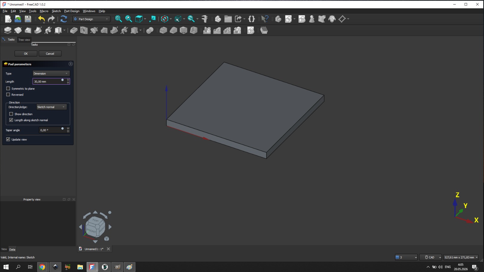
- Pad — gave it depth, got a 3D rectangular enclosure
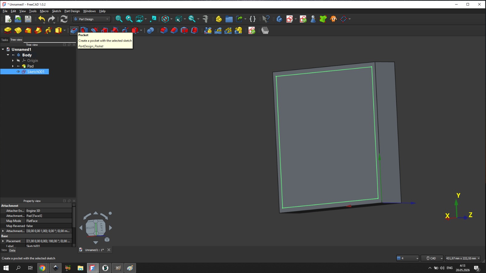
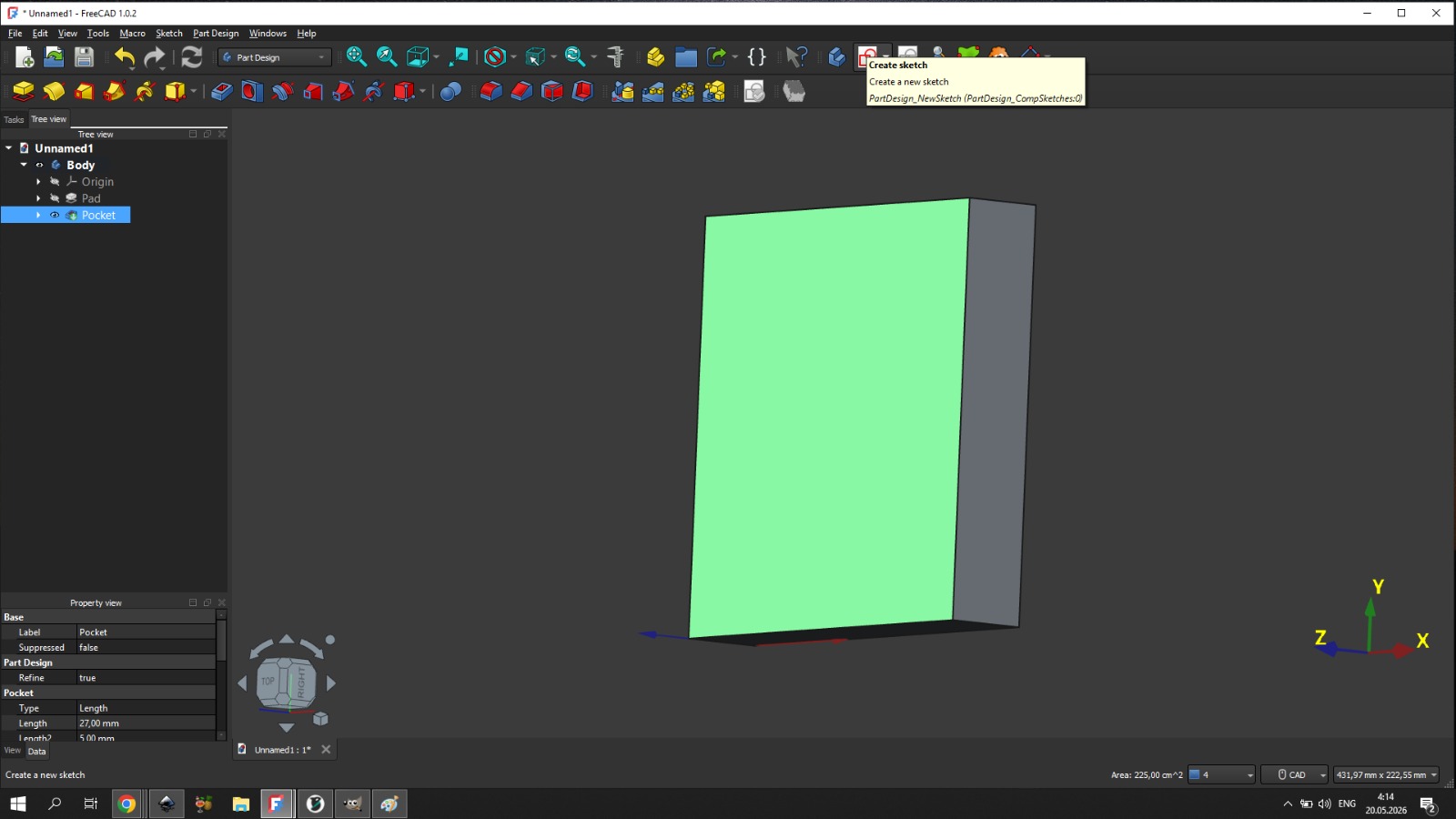
- Switched to the front face, created a new Sketch
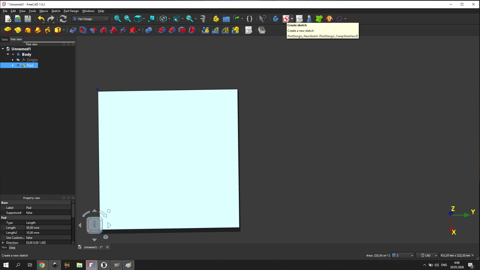
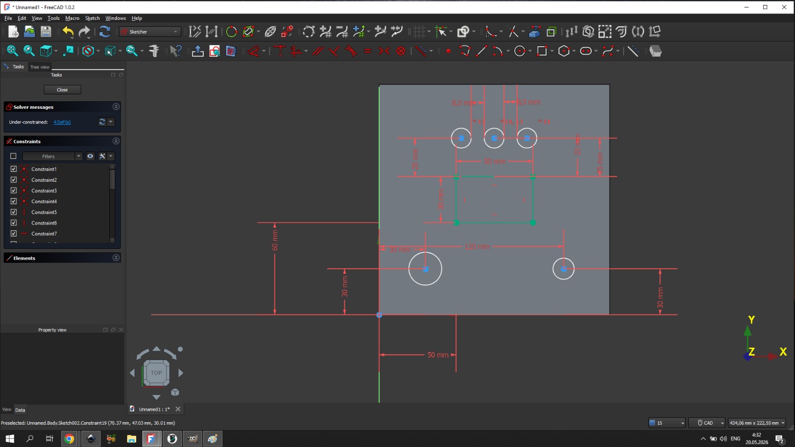
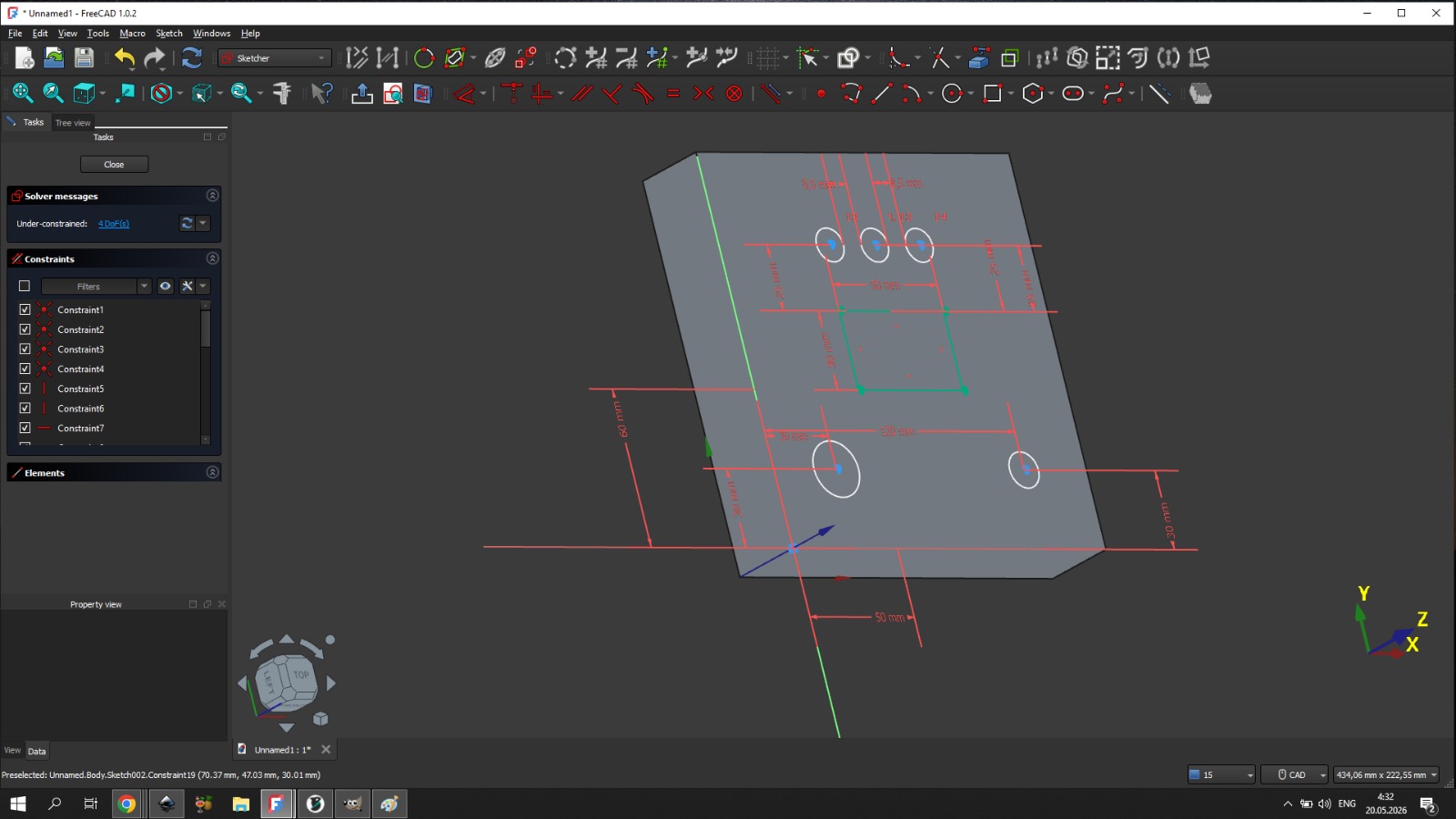
- Used the Pocket tool to create openings:
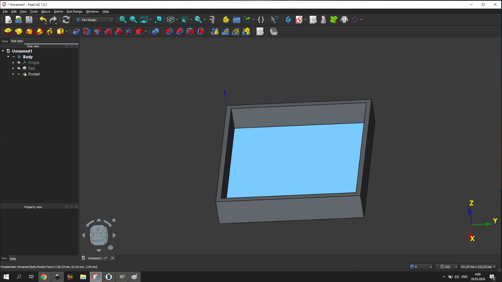
- Center rectangle — display opening
- Bottom left circle — CO₂ sensor hole
- Right circle — emergency button position
- Three small circles at the top — LED holes
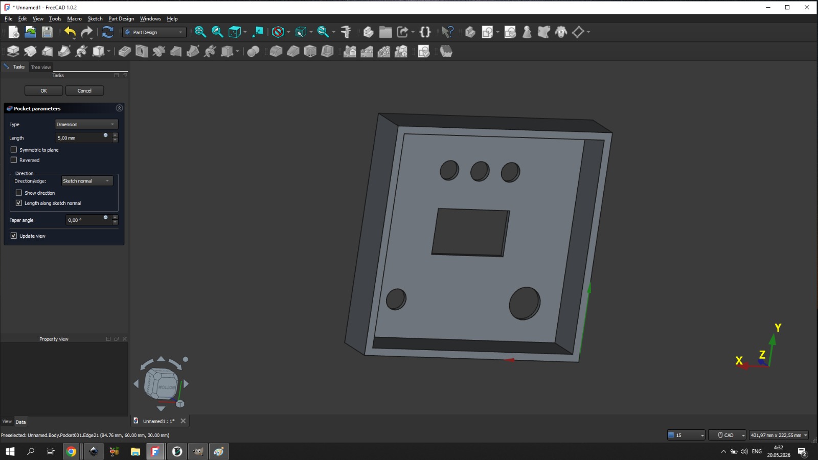
Pocket is essentially the opposite of Pad — Pad adds material, Pocket removes it. Once I understood that logic, everything became much easier.
I also modified the back of the enclosure, but I’ll refine that later once I know exactly which components I’ll use and what size they are.
Visualizing the Enclosure
To get a clearer sense of how the enclosure would actually look as a finished object, I set up a shaded, colored view of the model in FreeCAD using a semi-transparent material and an isometric perspective with a clean background.
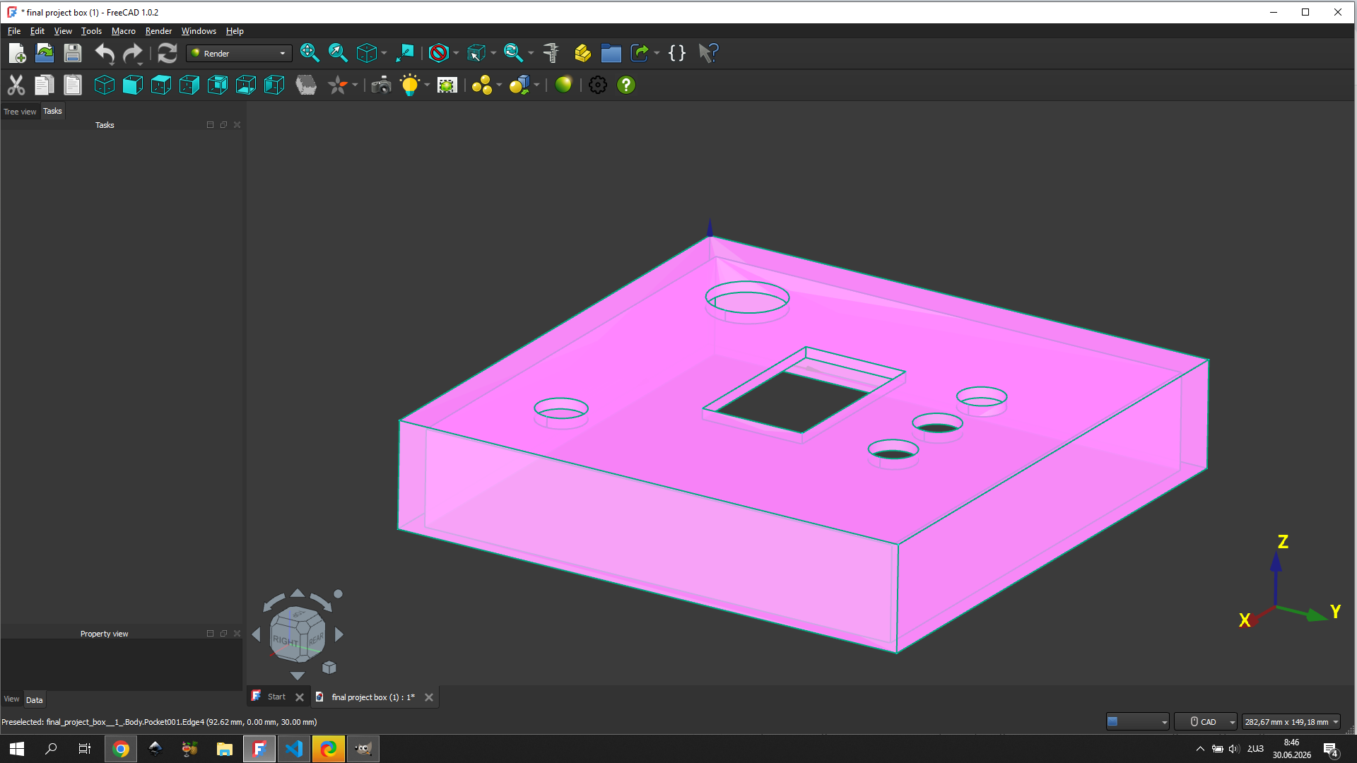
This kind of visualization helped me confirm the proportions and the placement of the openings before moving on to the next steps of the design — it’s a small thing, but seeing the enclosure rendered like a real object rather than flat gray geometry made it much easier to judge whether the layout actually made sense.
Rendering in Blender
Once the FreeCAD model was done, I wanted to produce a proper photorealistic render to better visualize the final enclosure. FreeCAD’s built-in shading is useful for checking geometry, but it can’t match the lighting and material quality of a dedicated render tool.
Importing the Model
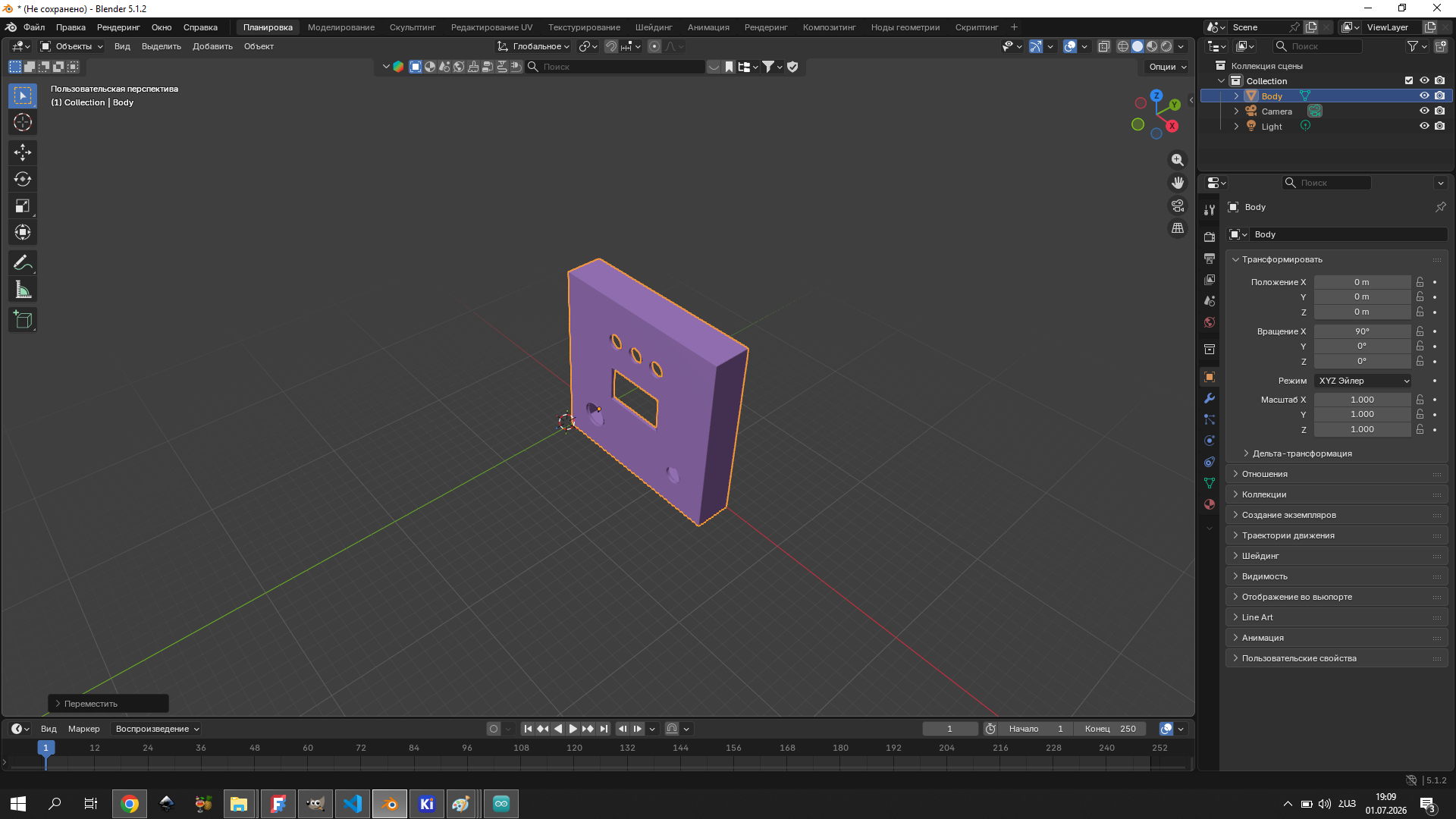
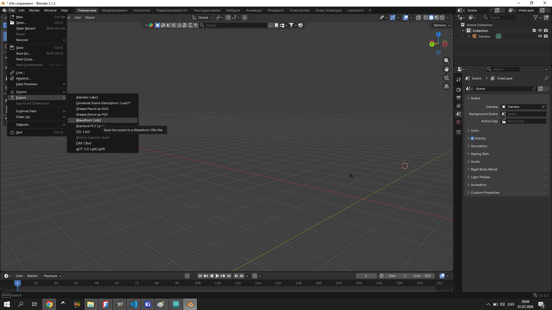
I exported the enclosure from FreeCAD as a Wavefront OBJ file using File → Export → Wavefront (.obj) (Ctrl+N), then opened Blender 5.1.2 and imported it via File → Import → Wavefront (.obj).
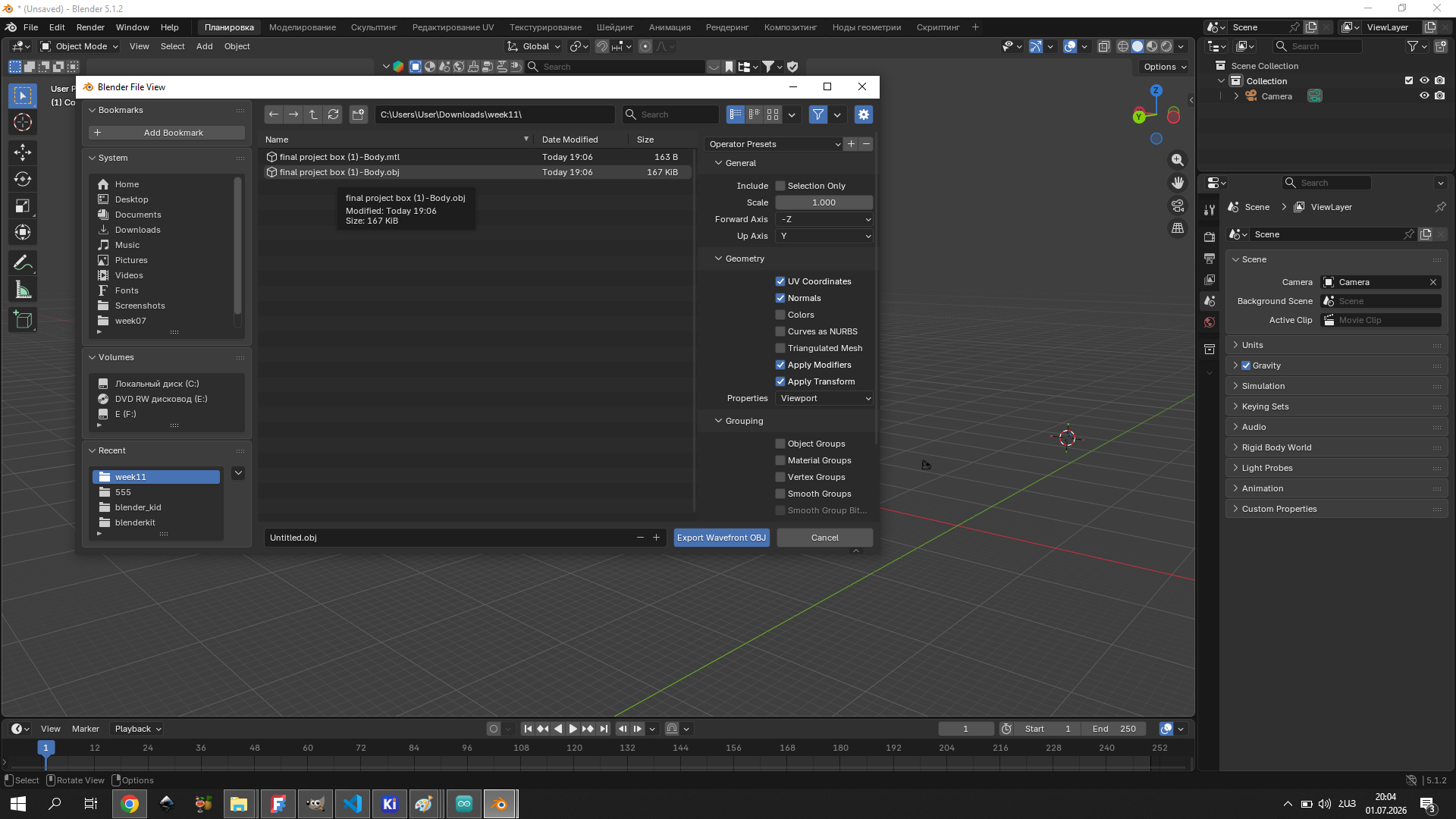
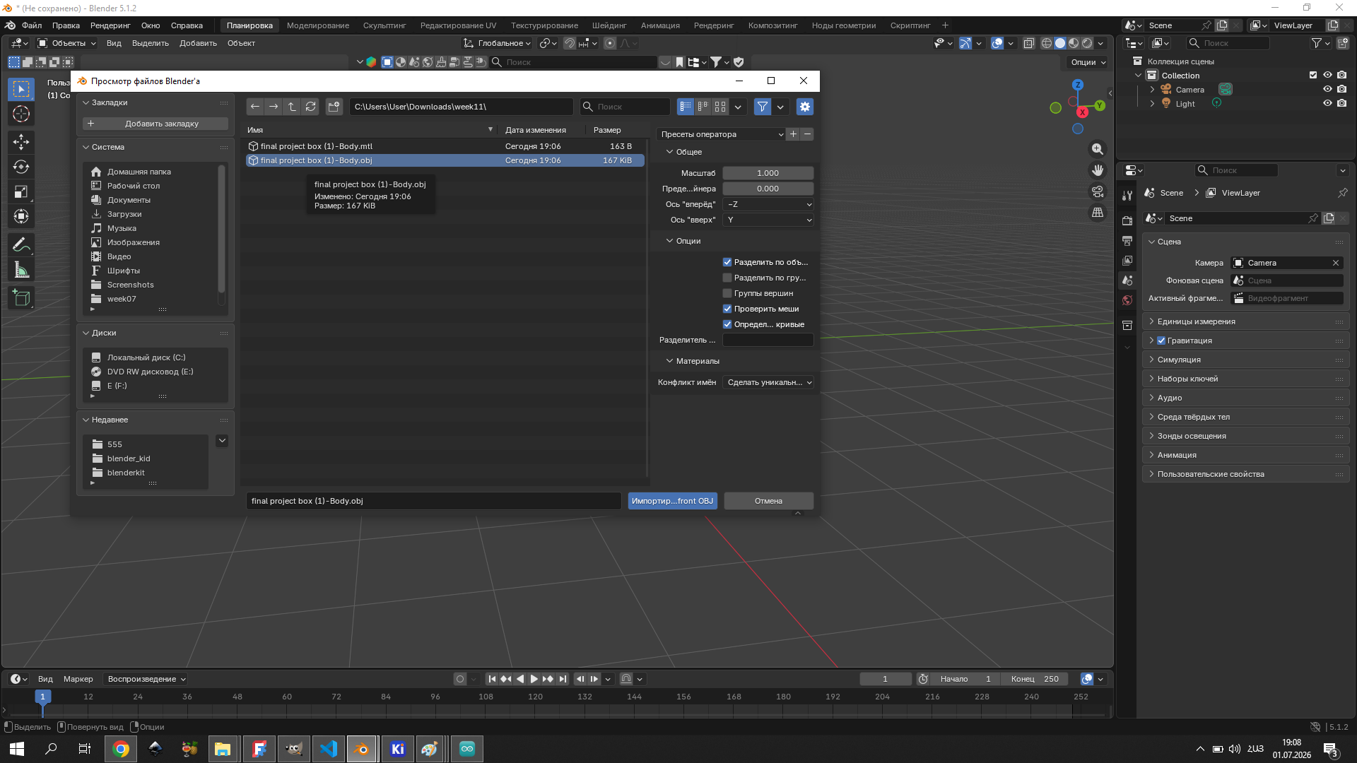
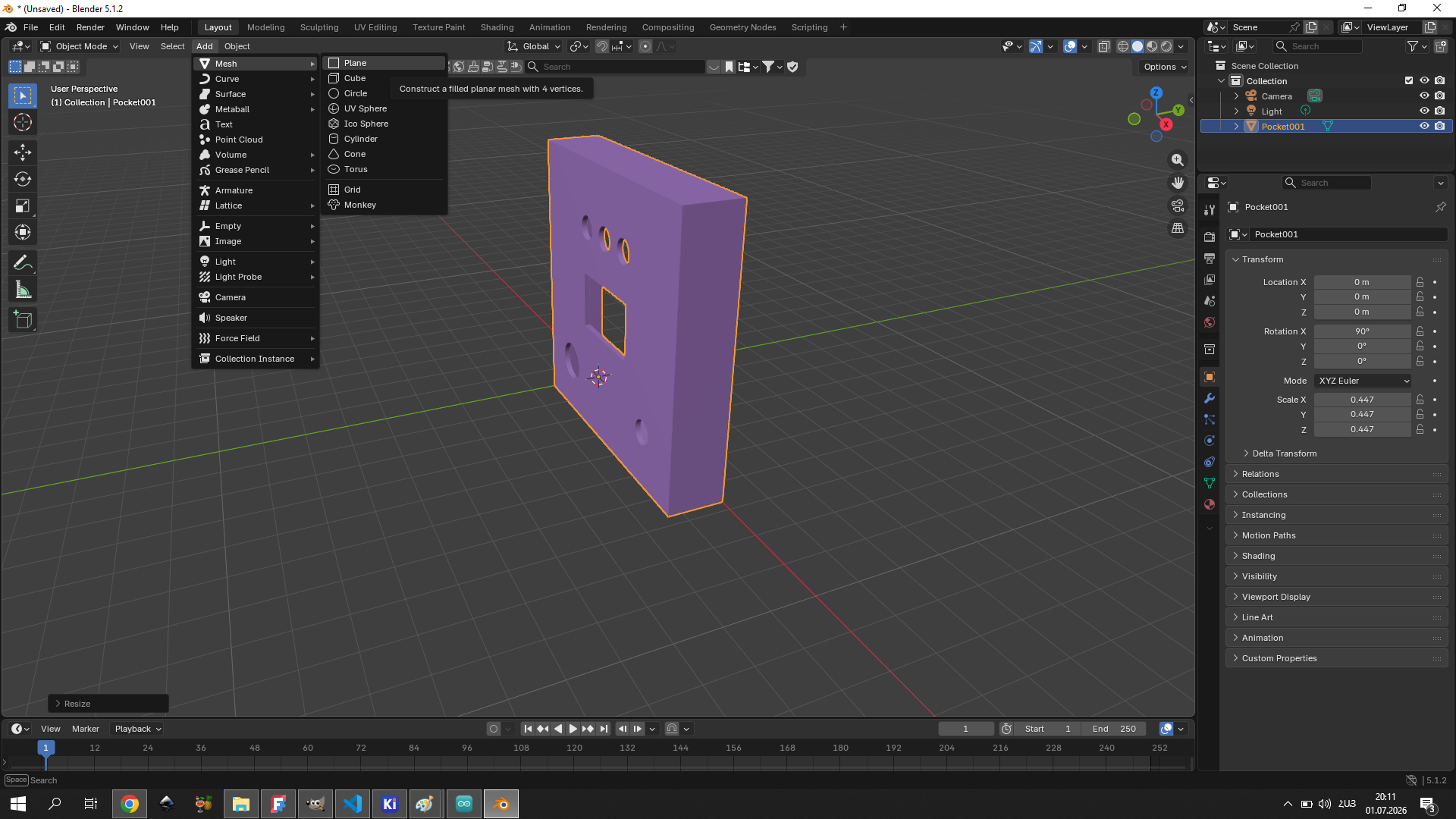
The model appeared in the Blender viewport with its geometry intact.
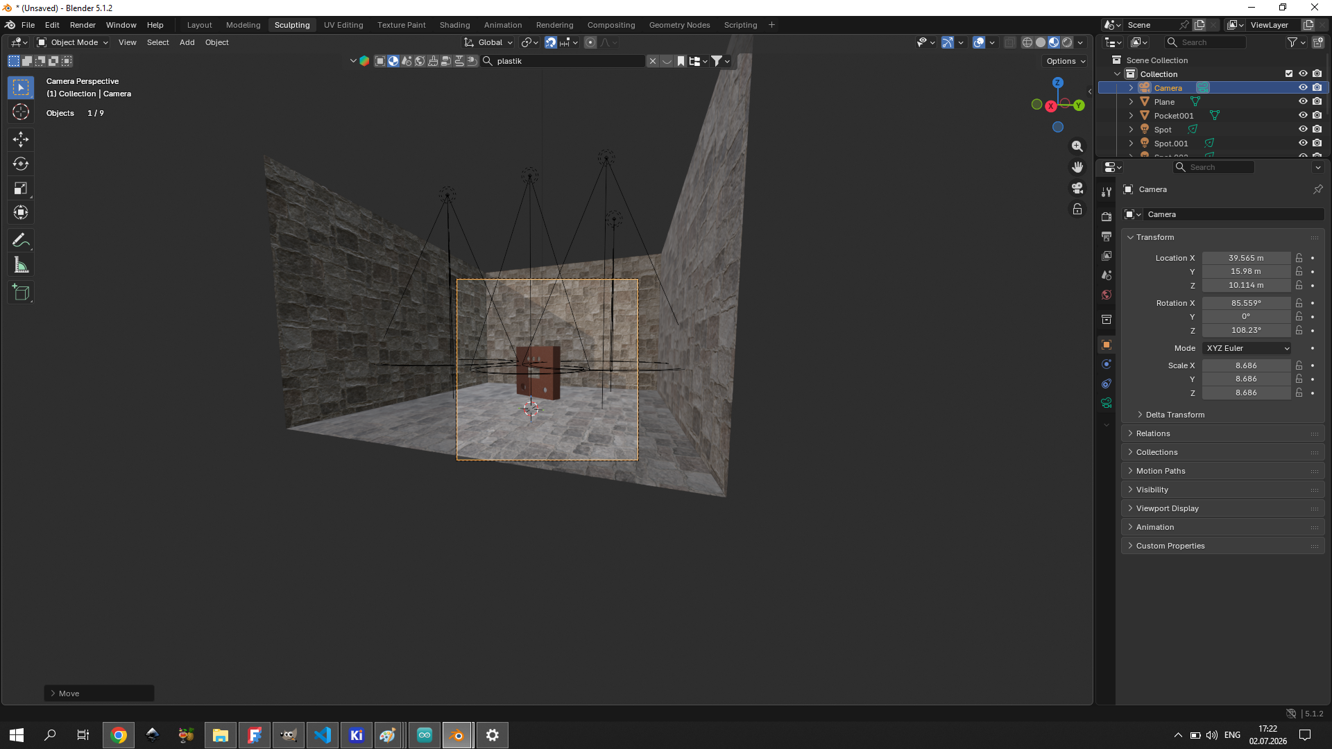
Setting Up the Scene
I added a Plane as a floor/backdrop using Shift+A → Mesh → Plane, then scaled it to fill the scene.
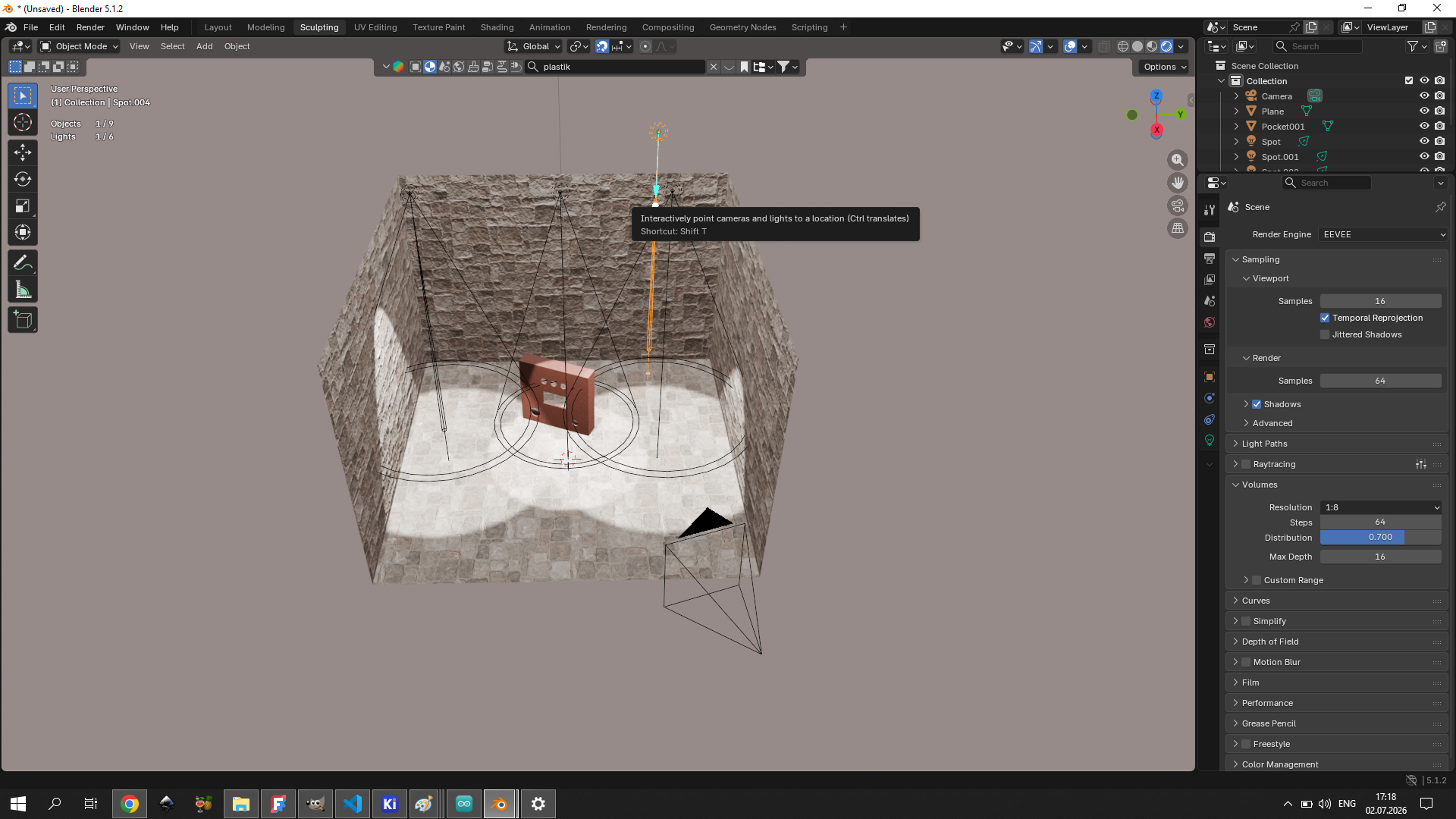
Next I set up lighting. I added multiple Spot lights using Shift+A → Light → Spot, positioned them above the model, and used Shift+T (Track To) to aim each light directly at the enclosure.
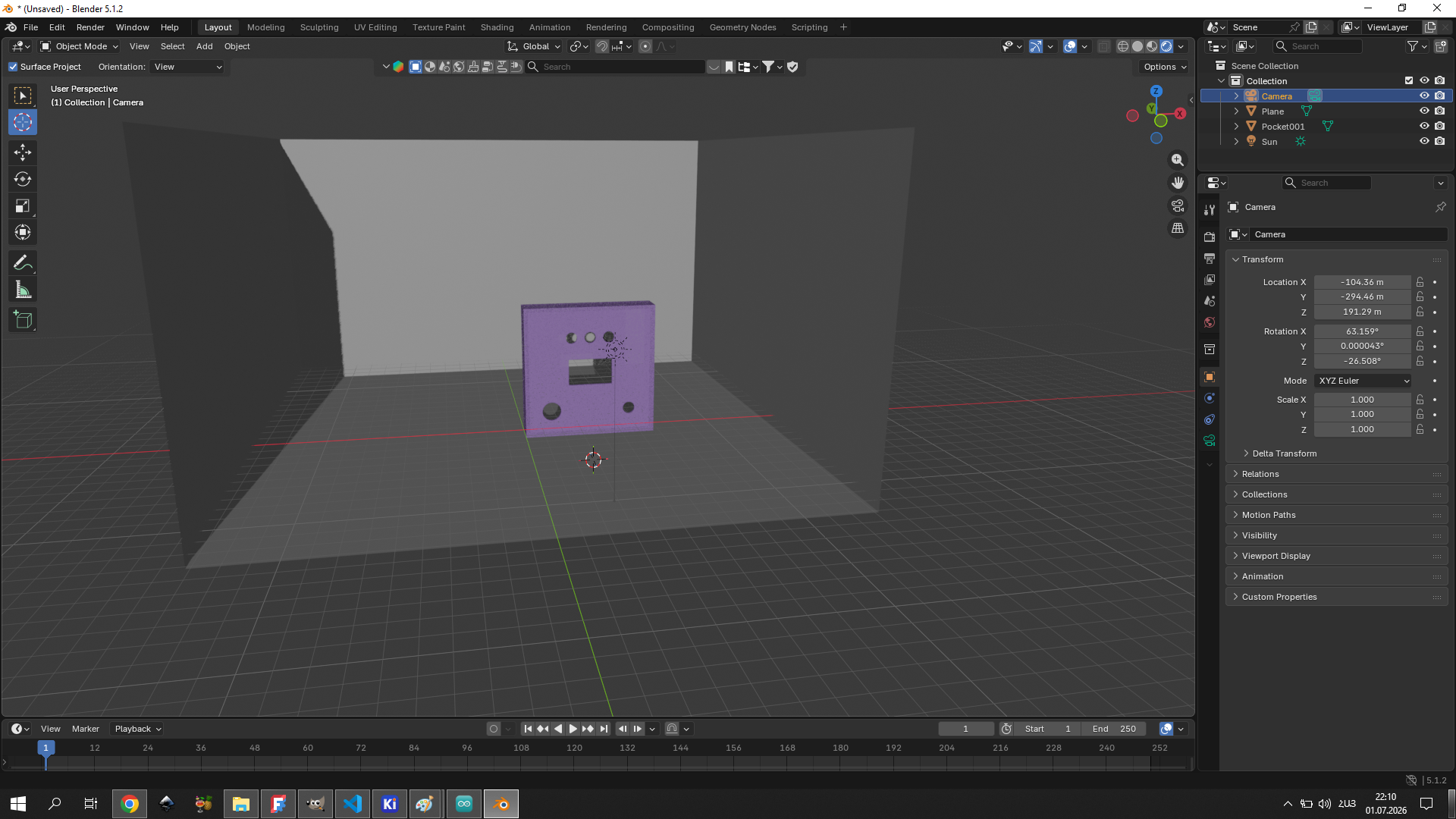
I also added a Camera and framed the shot using Numpad 0 to switch into Camera view.
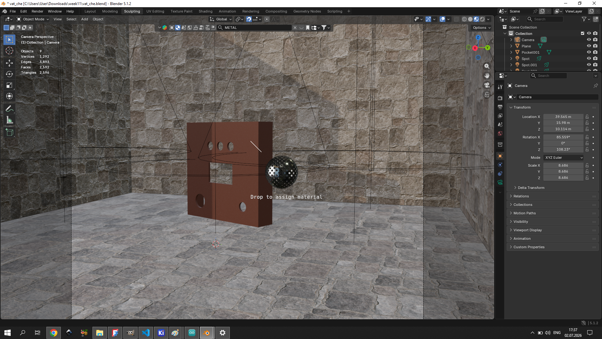
Applying Materials
I used BlenderKit to apply realistic materials. I dragged a plastic material onto the enclosure, then later tried a metal material for comparison.
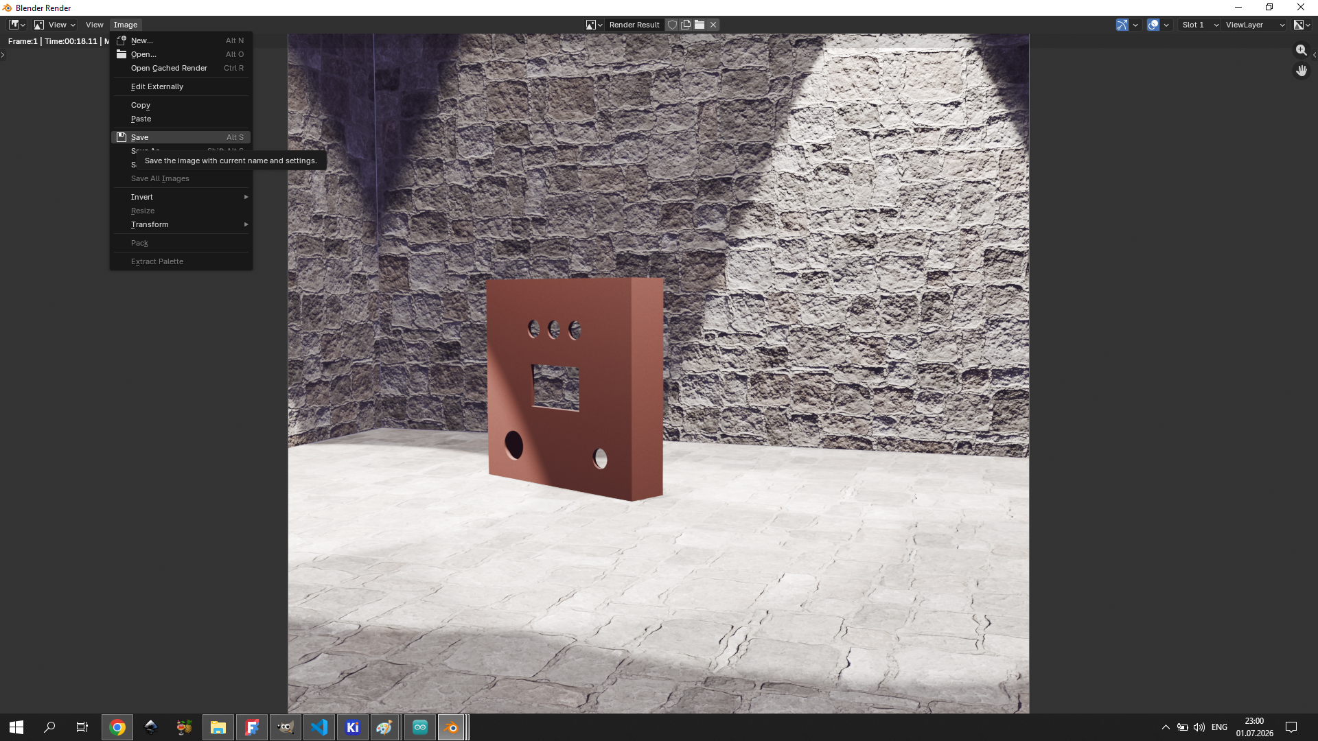
Rendering
I used the EEVEE render engine and rendered the scene via Render → Render Image. The result was saved from the render window using Image → Save (Alt+S).
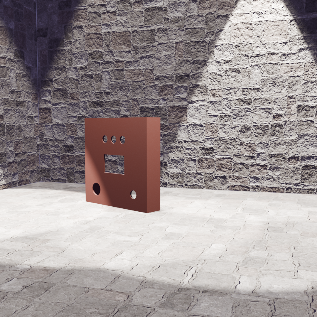
The render gave a much clearer picture of how the enclosure will look as a physical object — the material, the depth of the openings, and the proportions all became easier to evaluate under realistic lighting.
Reflection
This week I understood something important — even an imperfect, rough model is hugely useful. Before drawing and modeling, Smart Workshop was just words and an idea for me. Now I can concretely see what it is physically, what space each component will occupy, and what connections exist between them.
Inkscape helped me understand the logic of the system — who receives a signal from whom, who sends a command to whom. FreeCAD showed me the physical reality — does everything fit, is the layout logical.
The final design will look very different from all of this, but this step was necessary. Now when the actual components arrive in my hands, I know what questions to ask and what to check.