5. 3D Scanning and Printing
The image of my individual work is presented below.
Assignment
This week focused on studying 3D printing and scanning processes, with particular attention to machine limitations, parameter calibration, and material behavior.
The main objective was to analyze machine performance and establish practical design rules ensuring reliable and high-quality fabrication.
Design Goals
- Understand limitations of FDM printing
- Study surface quality and layer adhesion
- Analyze overhang performance
- Evaluate volumetric extrusion limits
- Define optimal printing parameters
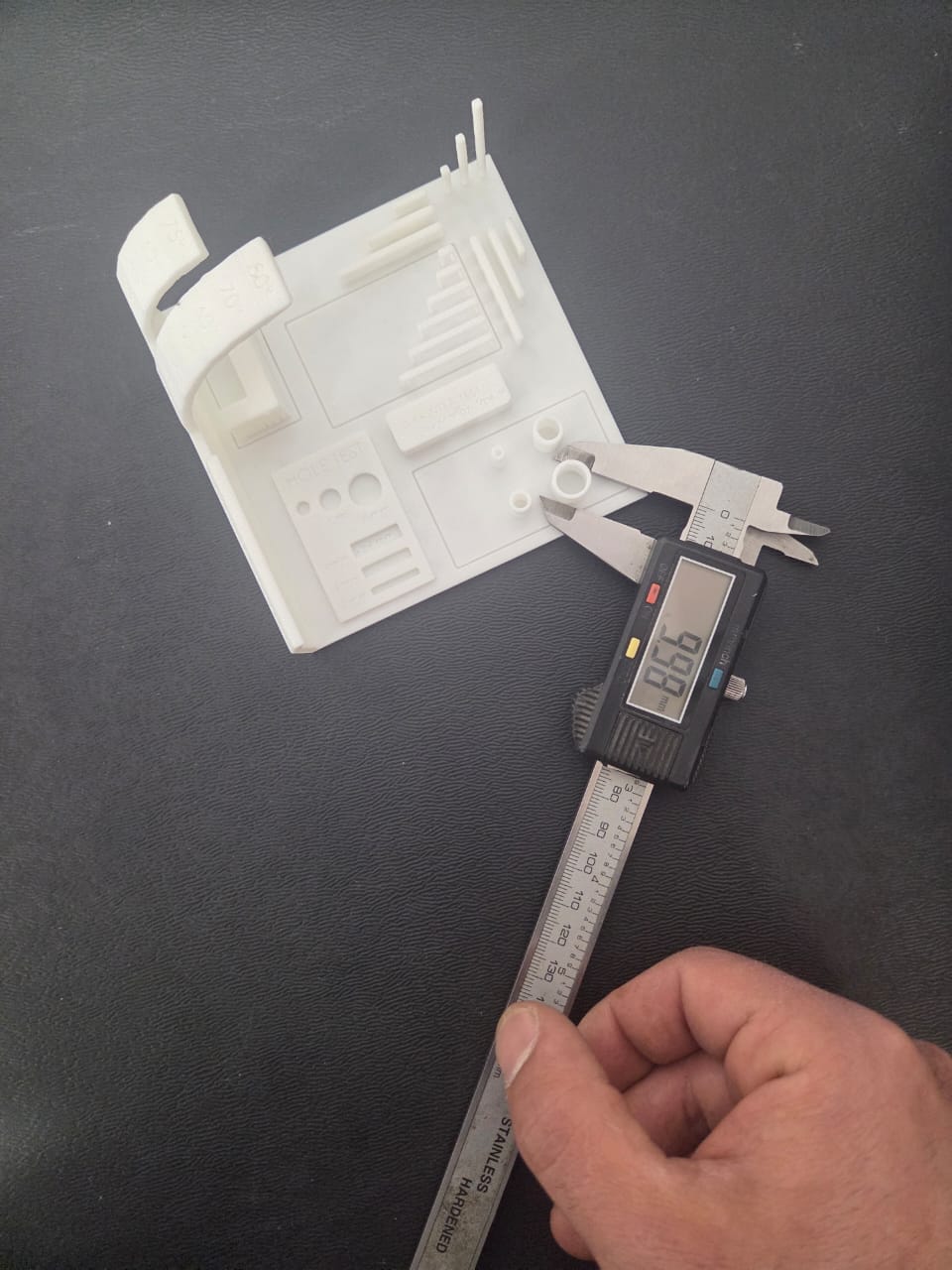
Group Assignment — Machine Testing
During the group assignment, the available laboratory printers were analyzed to understand their real-world performance and technical constraints.
Testing included:
- Surface quality evaluation
- Layer adhesion analysis
- Overhang capability testing
- Dimensional stability assessment
- Material behaviour comparison
Machine Analysis
Test prints were conducted using two different materials: PLA and PETG.
I worked with PETG, while Ani used PLA. This allowed comparison of both printer performance and material behavior under identical conditions.
Using identical test files and controlled slicing parameters ensured a fair comparison.
Evaluation Focus
- Thermal stability
- Layer adhesion
- Extrusion consistency
- Surface quality
- Print speed influence
Printing Experiments
- Calibration models
- Overhang testing
- Speed and quality comparison
- Structural strength evaluation
Personal Reflection — Group Assignment
Working with PETG during the group assignment made one thing clear to me — every material behaves differently, and understanding that behavior takes actual testing. You can read the specs, but until you run a temperature tower and see where stringing starts or where adhesion weakens, you don’t really know the material.
That’s why calibration matters. The same printer, the same slicer settings, but a different filament — and the results change completely. Knowing at what parameters your material performs best is what makes the difference between a reliable print and a failed one.
Slicing Workflow — Orca Slicer Selection
During the project, different slicing software options were available such as PrusaSlicer, but Orca Slicer was selected.
Orca Slicer allows precise control of:
- Layer height
- Infill
- Print speed
- Temperature
- Advanced fabrication parameters
Its visual feedback and fast parameter iteration made it ideal for workflow optimization.
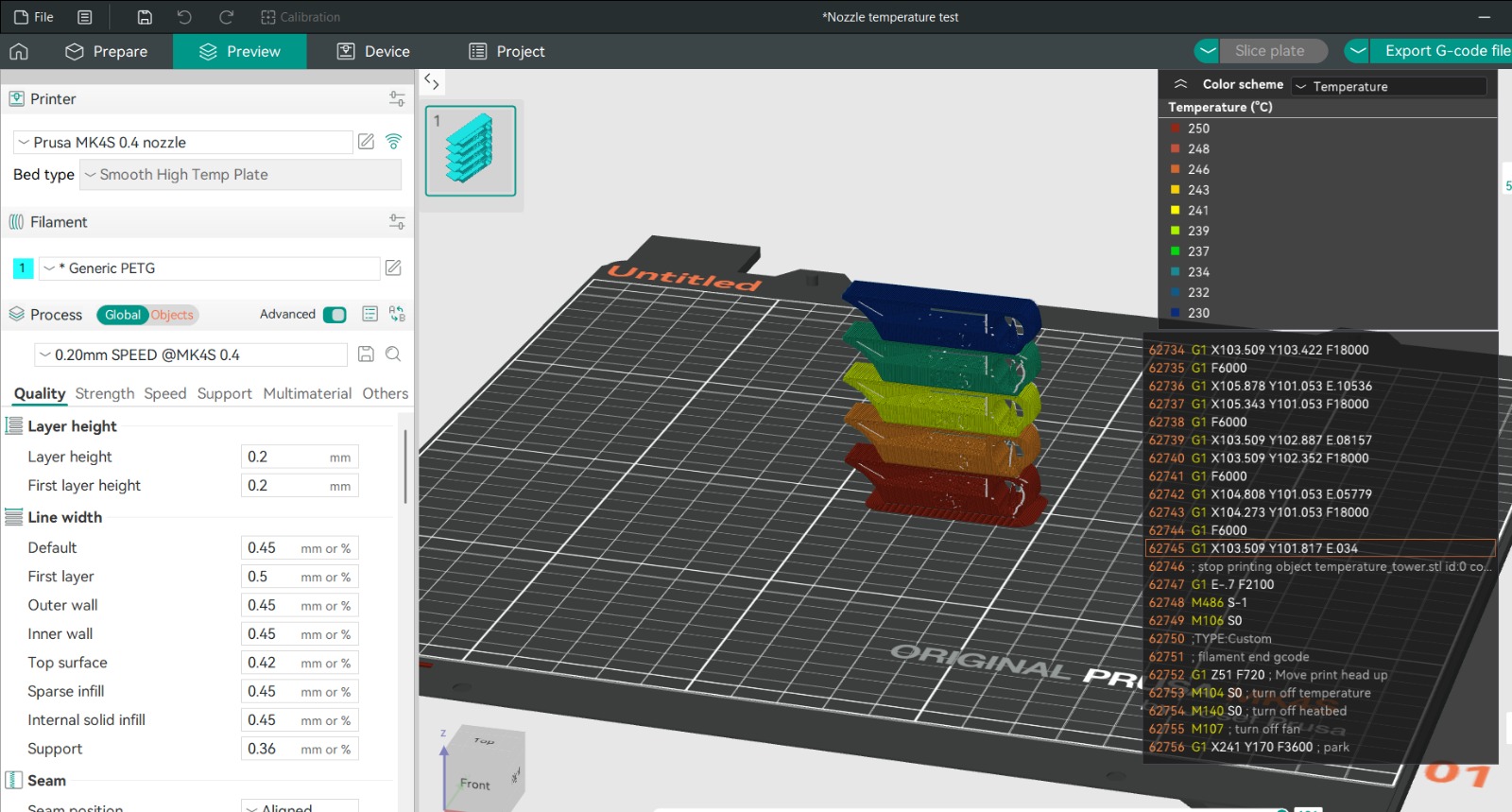
Temperature Tower Calibration
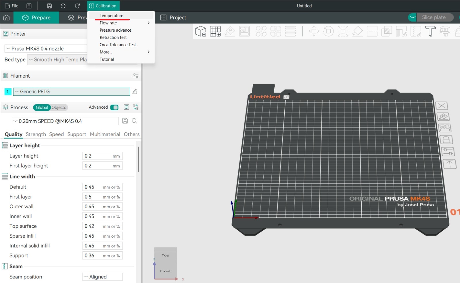 Before the main testing phase, calibration was performed using PETG filament.
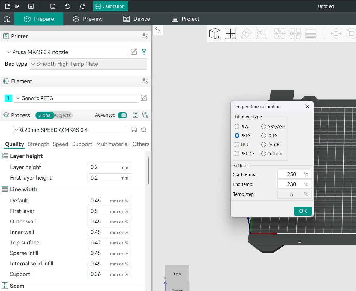
Calibration → Temperature in Orca Slicer.
Settings:
- Start temperature: 250°C
- End temperature: 230°C
- Step: 5°C
Each tower section printed at a different temperature.
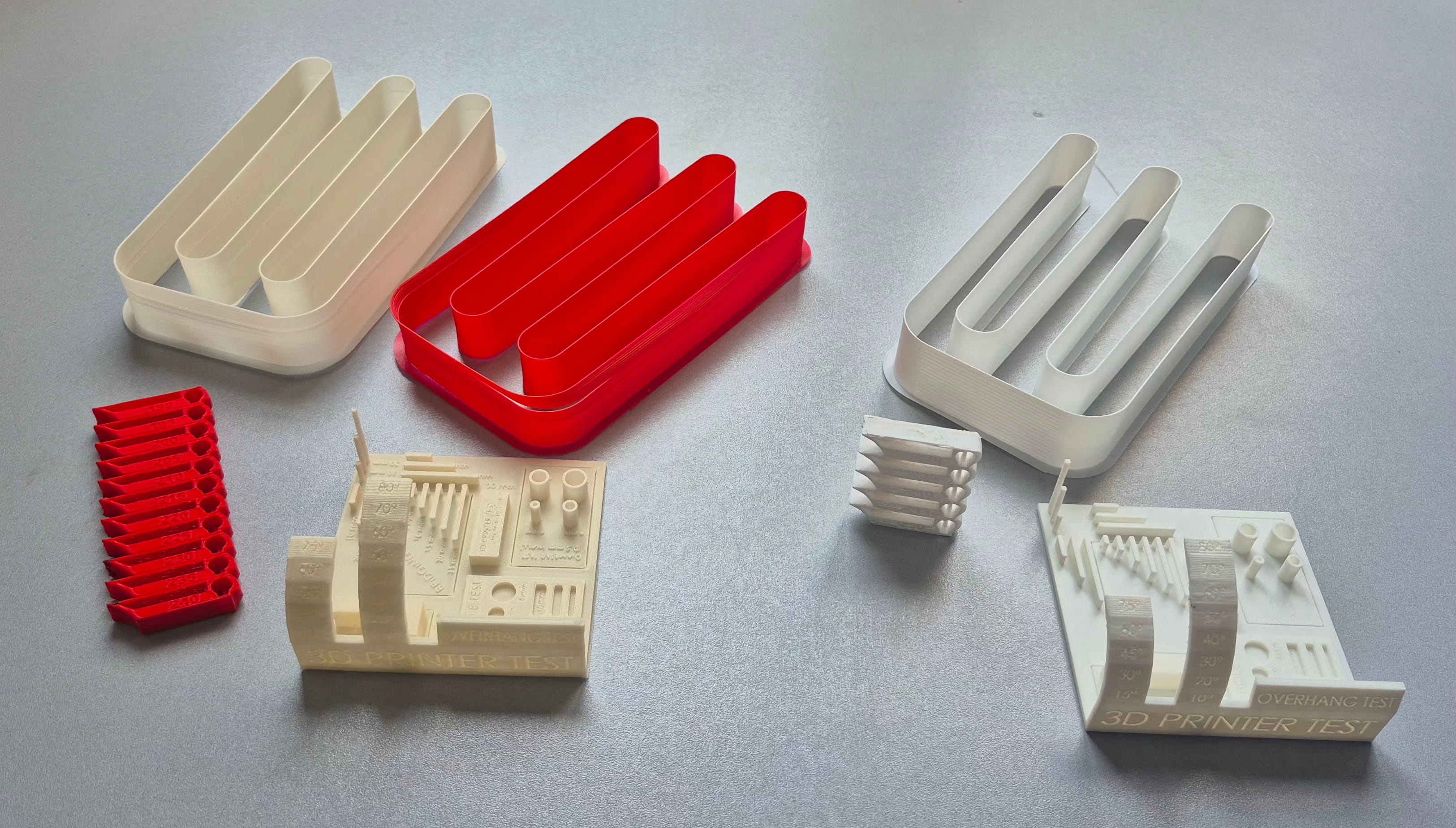
Temperature Tower Results
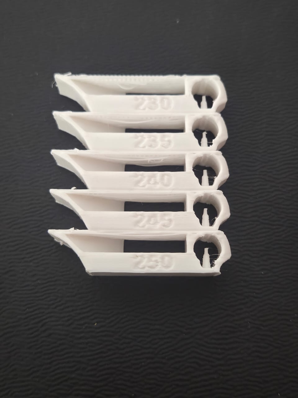
Each section ranged from 230°C–250°C.
Best quality observed around:
240°C
Lower temps:
- slight under-extrusion
- weaker adhesion
Higher temps:
- overheating
- stringing
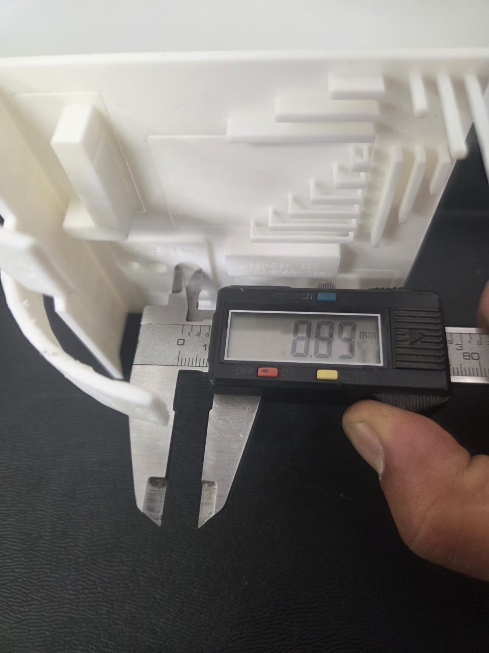
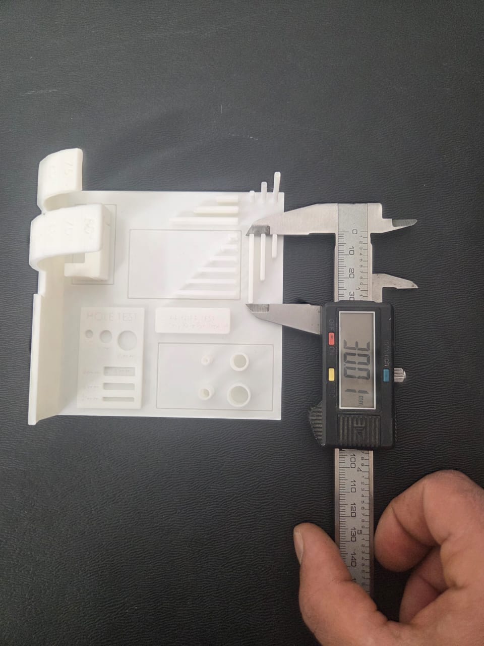
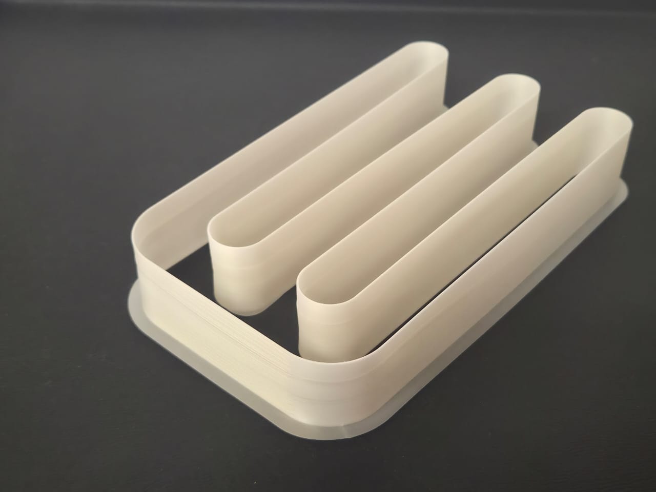
Maximum Flow Rate Calibration
Next step was evaluating volumetric flow limit using white PETG.
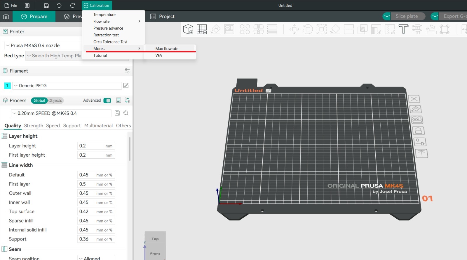
The slicer gradually increased extrusion demand.
Final slicer setting adjusted accordingly.
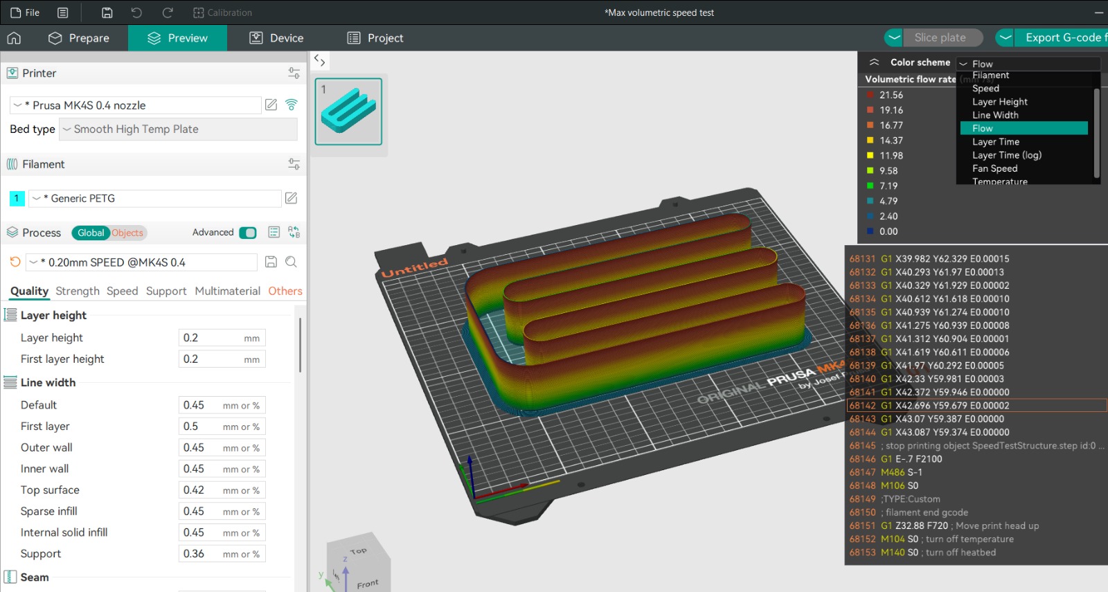
Observed parameters
- Surface consistency
- Layer adhesion
- Under-extrusion signs
- Line gaps
- Structural deformation
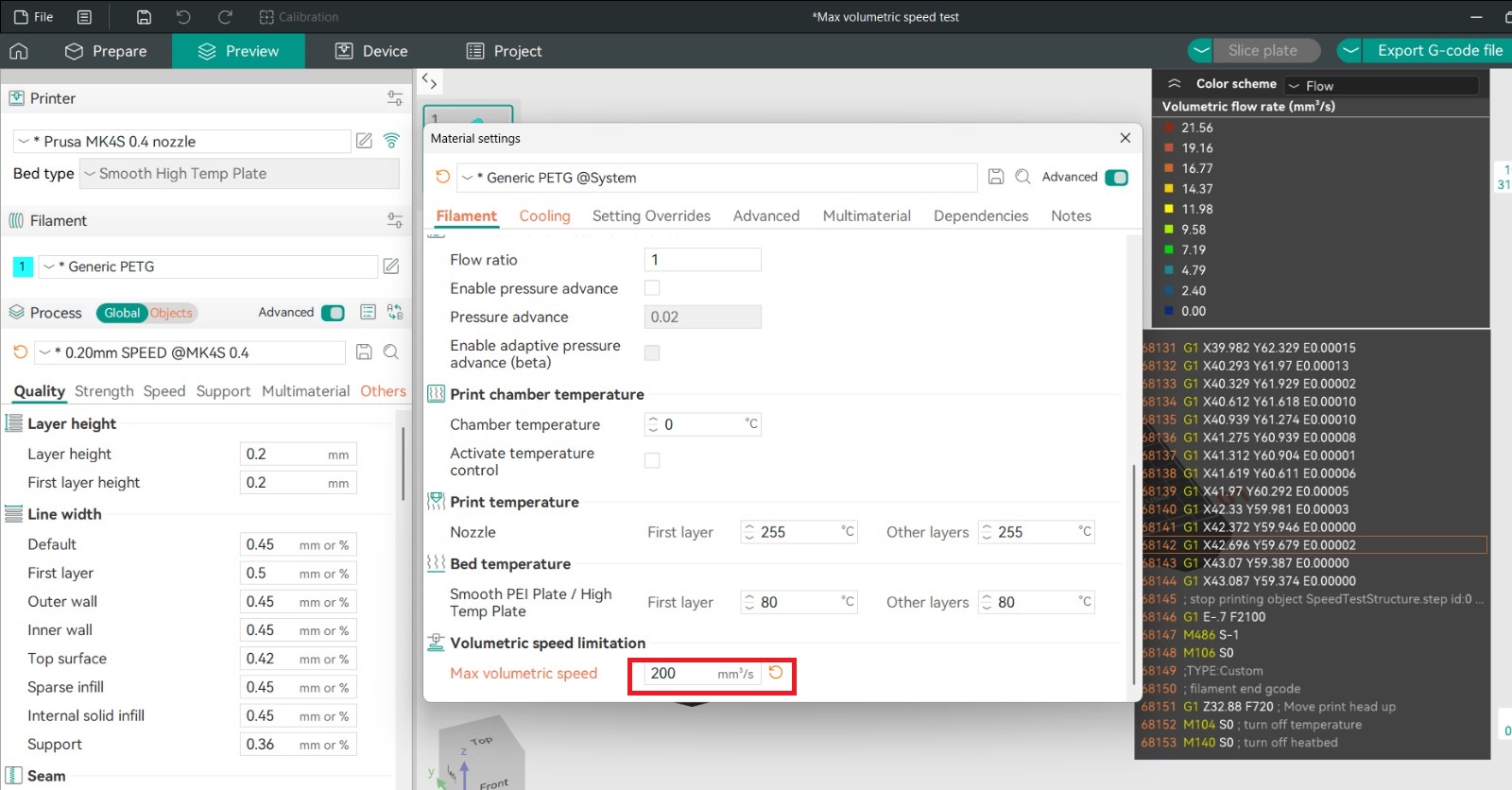
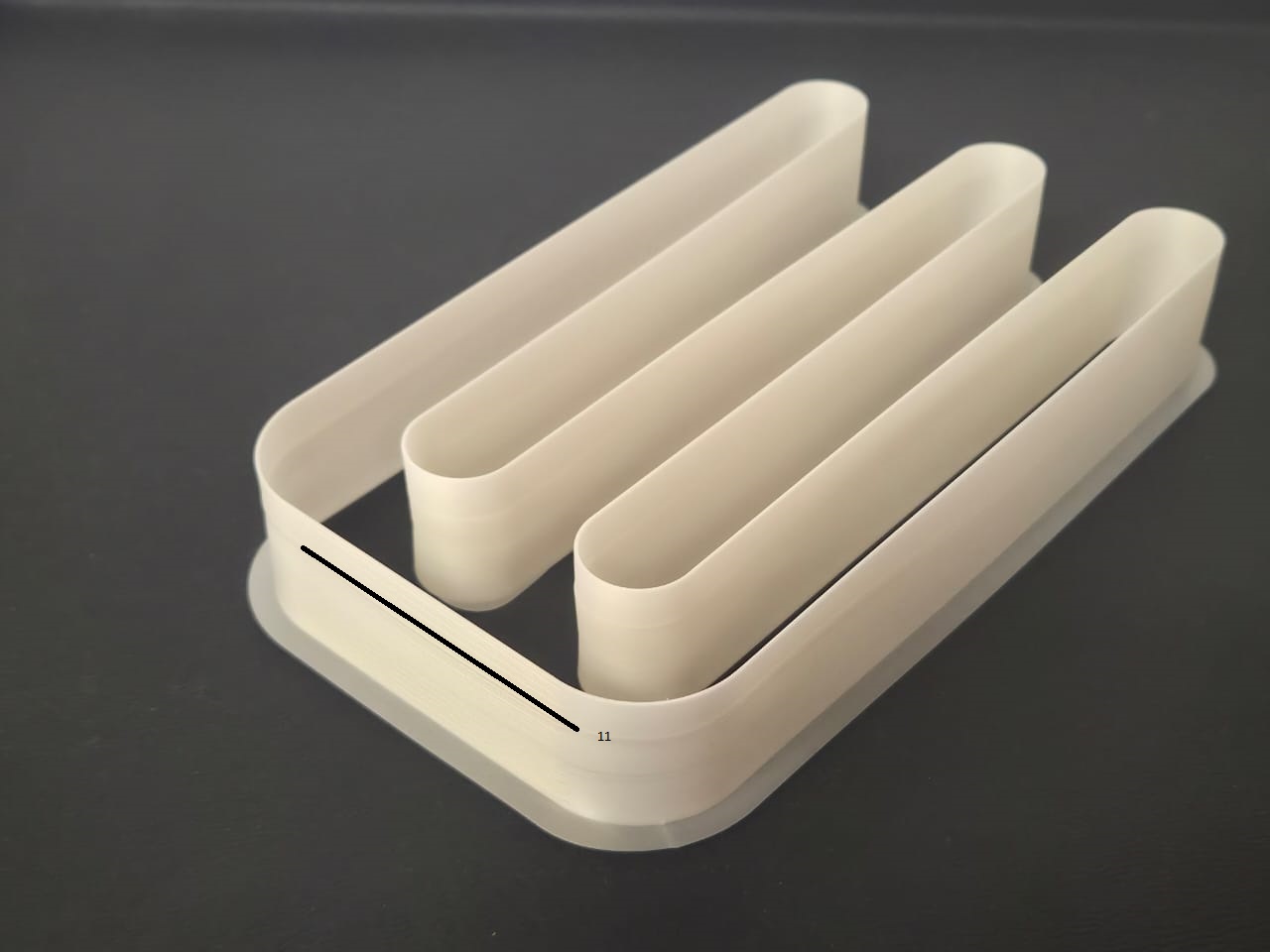
Observations
Quality degradation began around line 11.
Calculation:
Flow = 5 + (0.5 × 11)
10.5 mm³/s
Conclusion
Maximum stable flow rate:
10.5 mm³/s
Higher values reduced quality.
Machines Used
Prusa MK4S
- Build volume 250×210×210 mm
- Stable and reliable
Bambu Lab X1 Carbon
- High speed
- AMS system
Technical Comparison
| Specification | Prusa MK4S | Bambu Lab X1 Carbon |
|---|---|---|
| Technology | Cartesian | CoreXY |
| Volume | 250×210×220 | 256×256×256 |
| Nozzle | 0.4 | 0.4 |
| Max Temp | 290°C | 300°C |
Engineering Observations
- Speed impacts surface quality
- Overhang requires supports
- Calibration improves reliability
Reflection
Improved understanding of:
- Additive manufacturing limits
- Calibration workflow
- Fabrication-driven design
Individual Assignment
Design and print an object not manufacturable subtractively.
Workflow:
- CAD
- STL
- Slicer
- Documentation
Why Subtractive Manufacturing Is Not Possible
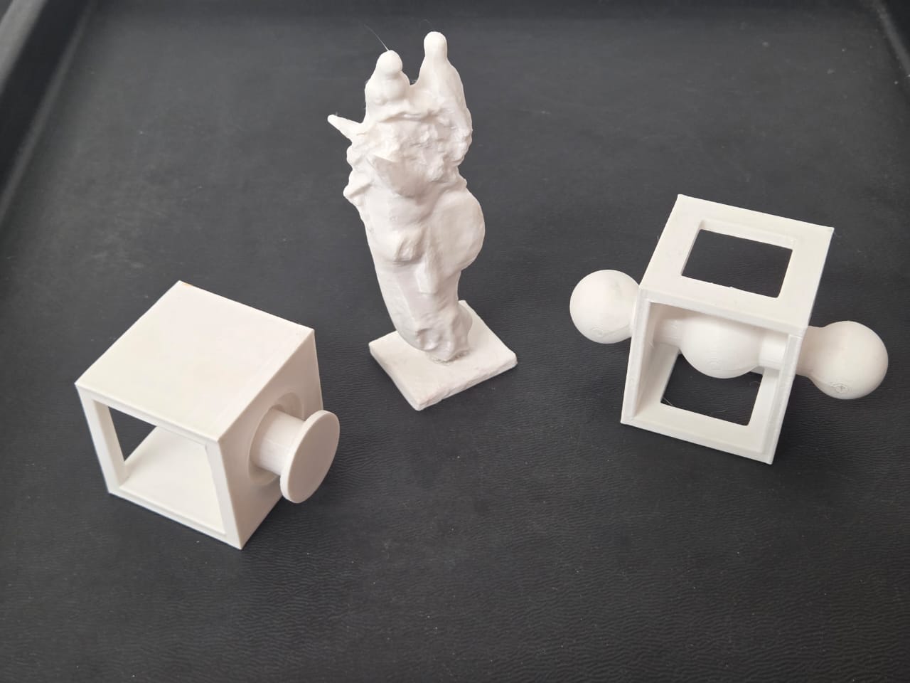
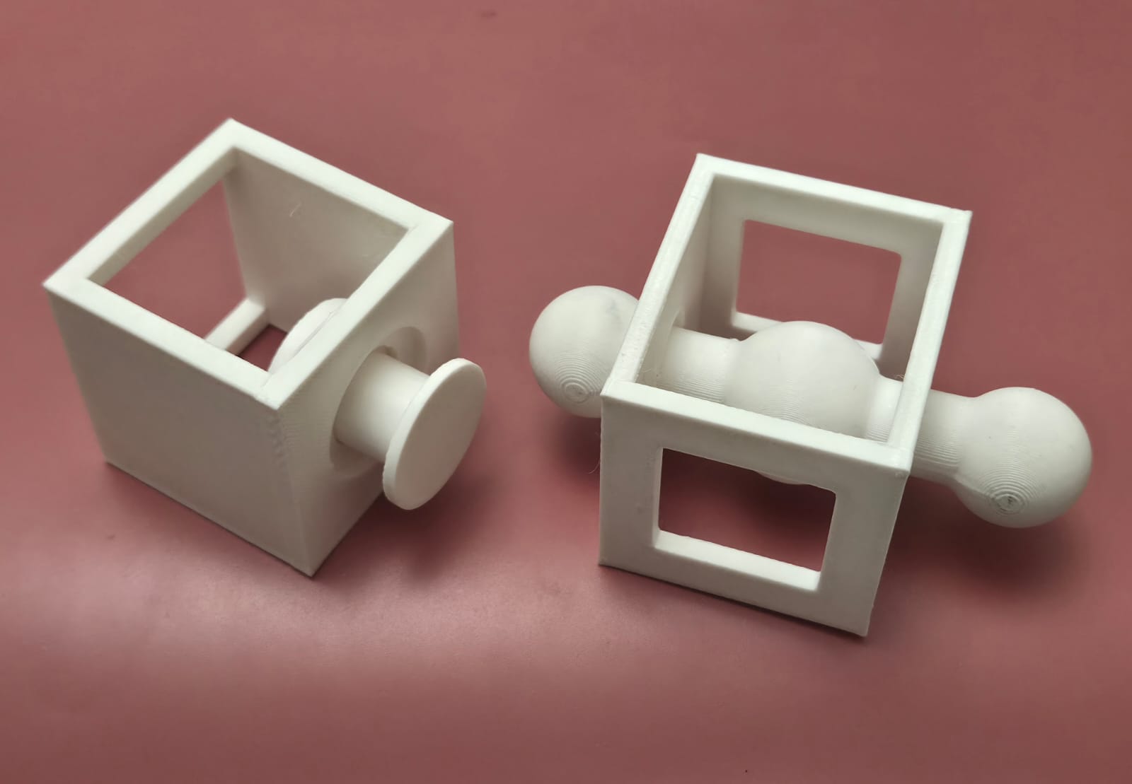
The designed object is a ball-in-cage mechanism — a hollow frame with a sphere captured inside, connected to a rotating handle. This geometry cannot be produced subtractively for several reasons.
A milling or turning tool requires unobstructed access to every surface it cuts. In this design, the sphere sits inside a closed cage structure. Once the cage walls are in place, no cutting tool can reach the ball from any direction without destroying the surrounding frame. The internal undercuts — the recesses that keep the ball from falling out — make it physically impossible to machine the interior in a single setup or even multiple setups.
Additionally, the entire assembly is a single continuous part. Subtractive methods would require fabricating at least three separate components (frame, ball, handle) and then assembling them, which would eliminate the defining feature of the design: the ball is permanently trapped inside the cage with no assembly joints.
3D printing solves this by building the geometry layer by layer. The ball and cage are printed simultaneously, with a small clearance gap between them. No assembly is needed.
Design Workflow
Sketch → Pad → Pocket → Opening → Mechanism → Final
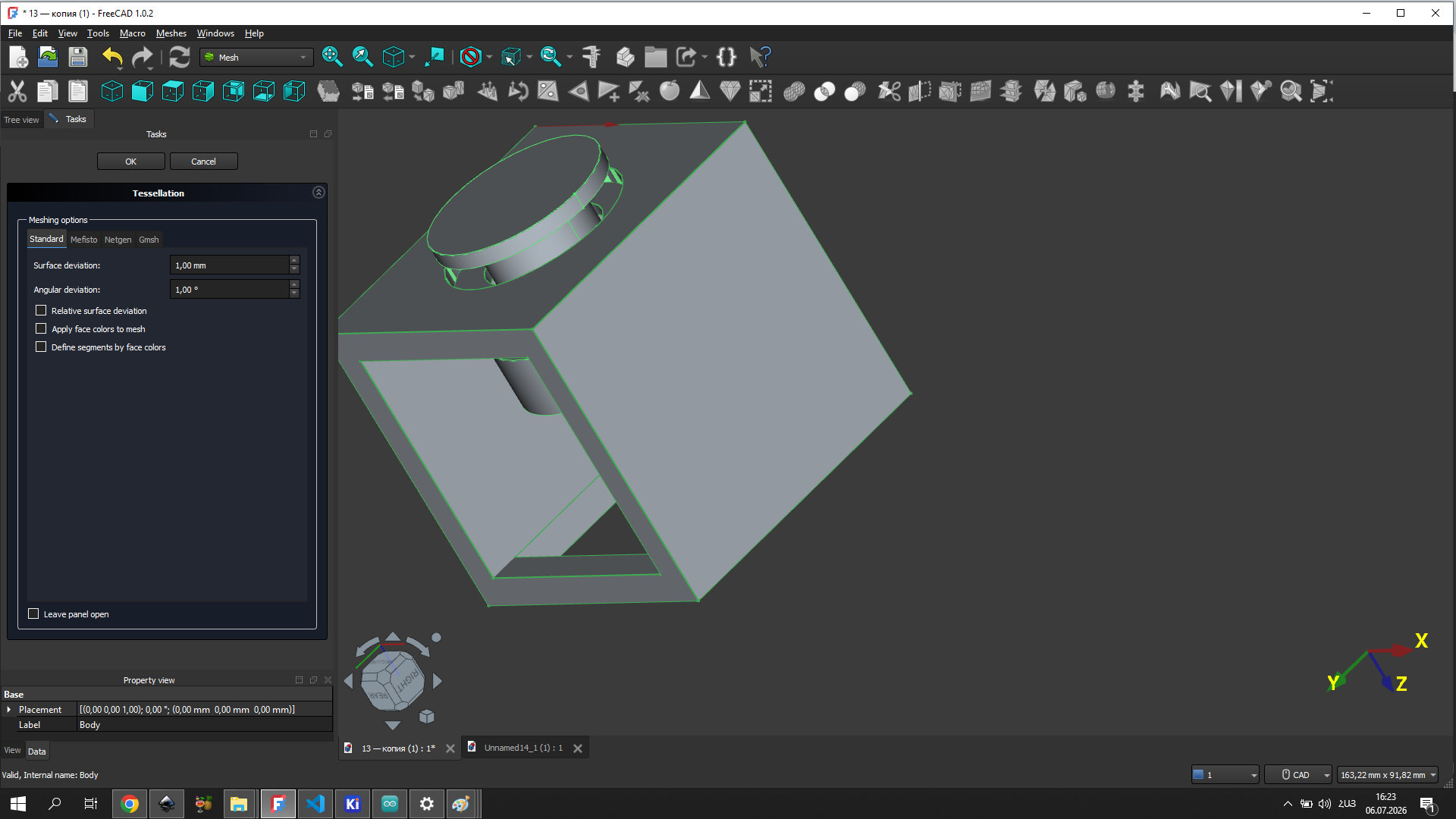
Design of the first model
I started with a rectangular sketch in FreeCAD that defined the outer dimensions of the cage frame. This became the foundation for all subsequent operations.
The sketch was extruded using the Pad operation to give the frame its height and create the basic 3D volume.
Pocket operations were used to cut out the openings on the sides of the cage. These openings are what make the interior visible and allow the ball to be seen inside the frame.
Additional openings were cut to complete the cage geometry and ensure the ball had enough clearance to rotate freely inside.
The sphere and handle were modeled separately and then positioned inside the cage with a small gap. This gap is what allows movement after printing — the parts are printed together but never fused.
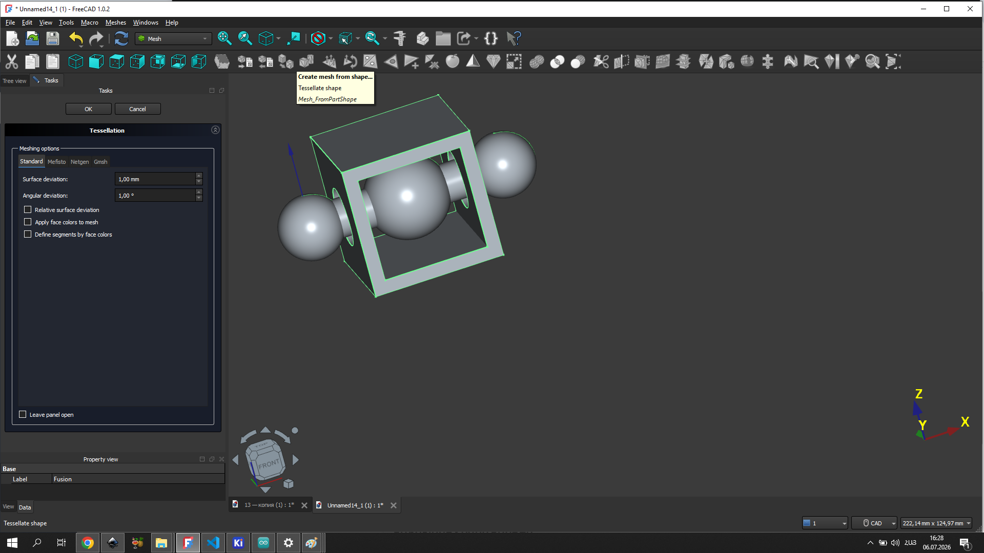
Design of the second model
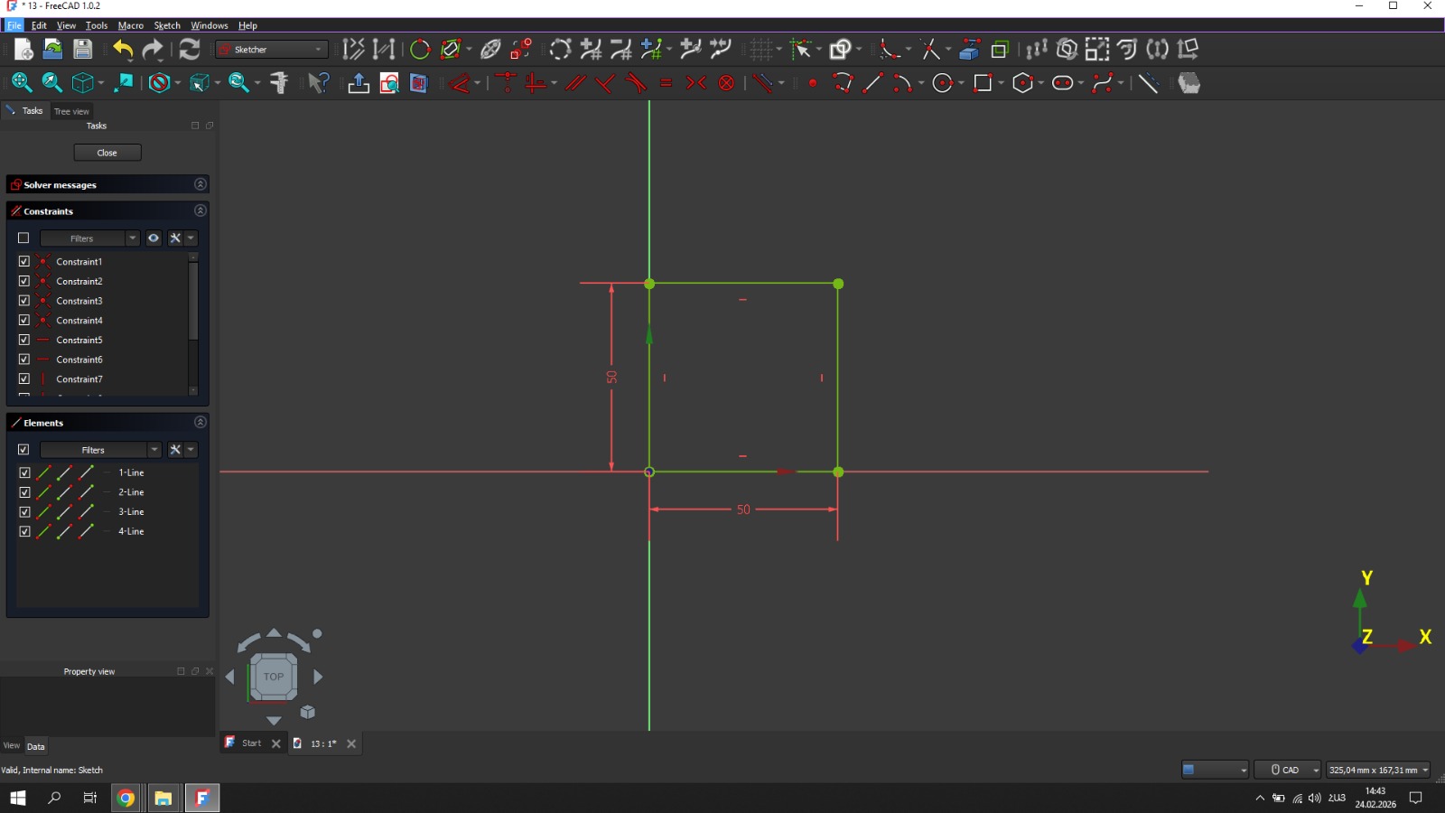
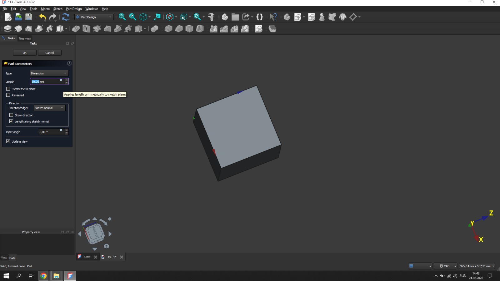
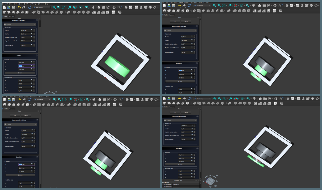
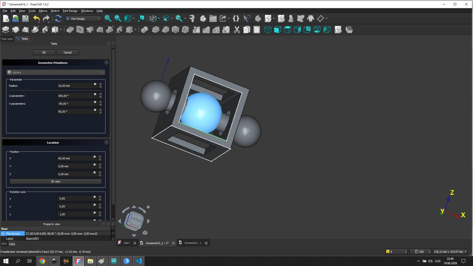
I designed my 3D model in FreeCAD. I created the main part of the model using the Part Design workbench, while the spheres were created using the Part workbench.
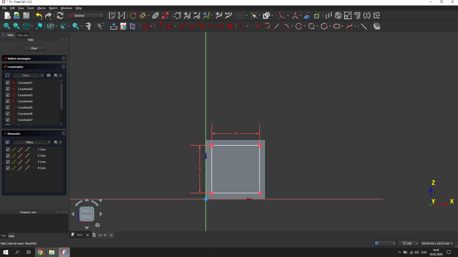
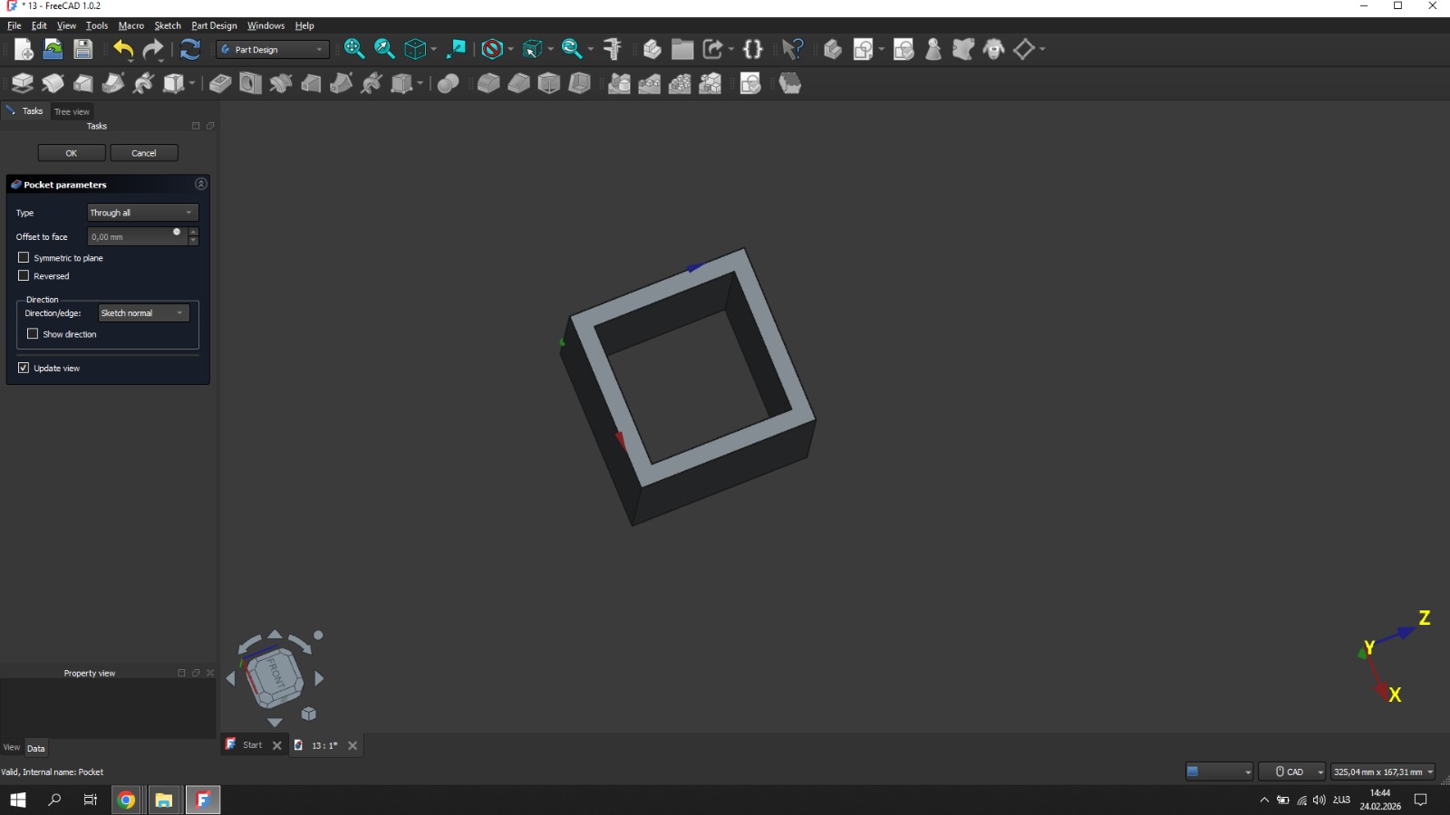
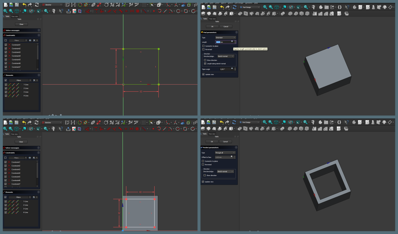
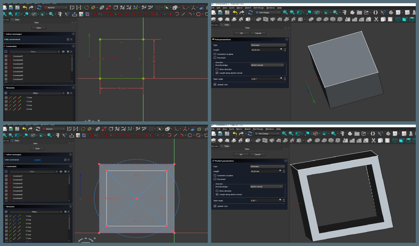
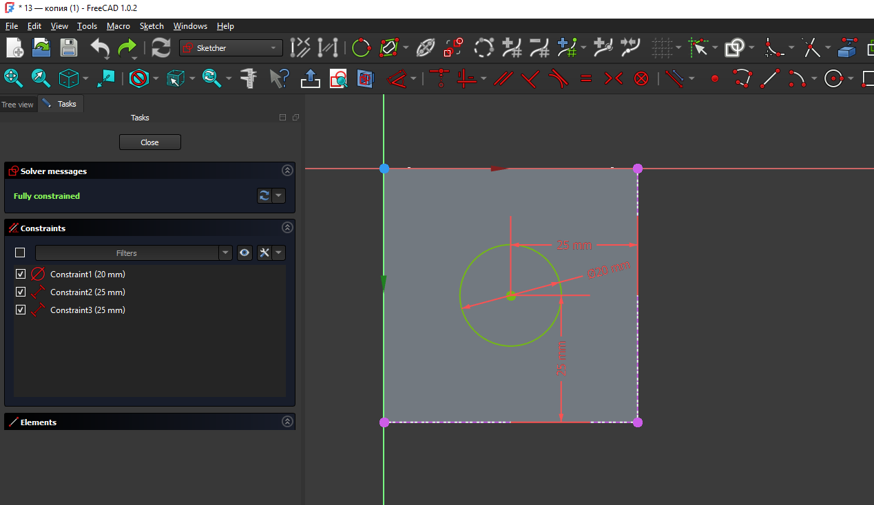
First, I created a 50 × 50 mm square sketch on the XY plane. After fully constraining the sketch, I used the Pad tool. Then, I created another 40 × 40 mm square sketch and used the Pocket tool to remove the inner material, creating a square frame.
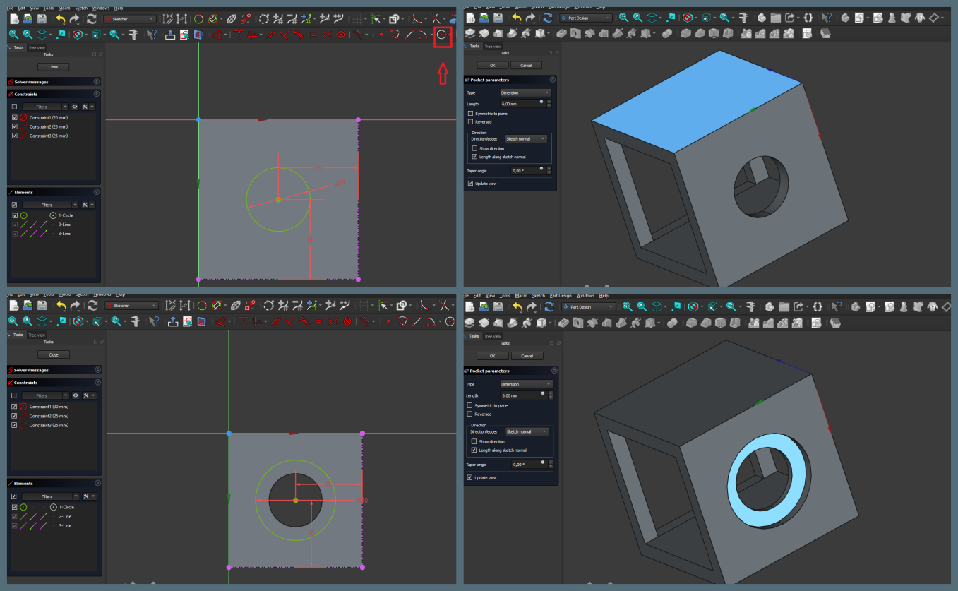
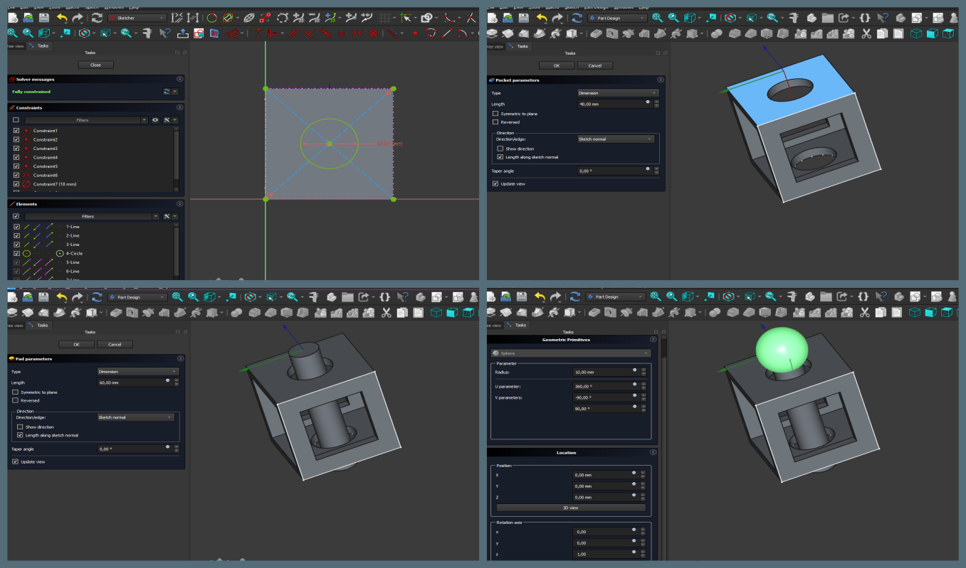
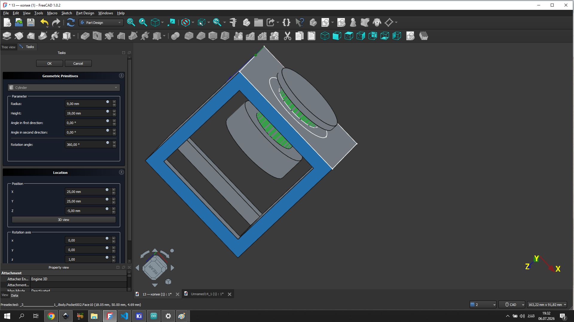
Next, I created the main body of the model using the Pad and Pocket tools. After that, I created another sketch and used the Pad tool to add the central cylinder.
After completing the main part of the model, I switched to the Part workbench and used Create Primitives → Sphere to create three spheres.
Finally, I positioned the spheres in their intended locations and obtained the final version of the model.
Clearance for 3D Printing
For the ball-in-cage mechanism to work after printing, there needs to be a small gap between the ball and the cage walls — enough that the parts don’t fuse together during printing but small enough that the ball stays inside. I set the hole diameter to 25 mm and the ball diameter to 20 mm, giving a 2.5 mm clearance on each side.
After editing, I saved the model in STL format so that it could be opened in the Orca Slicer software.
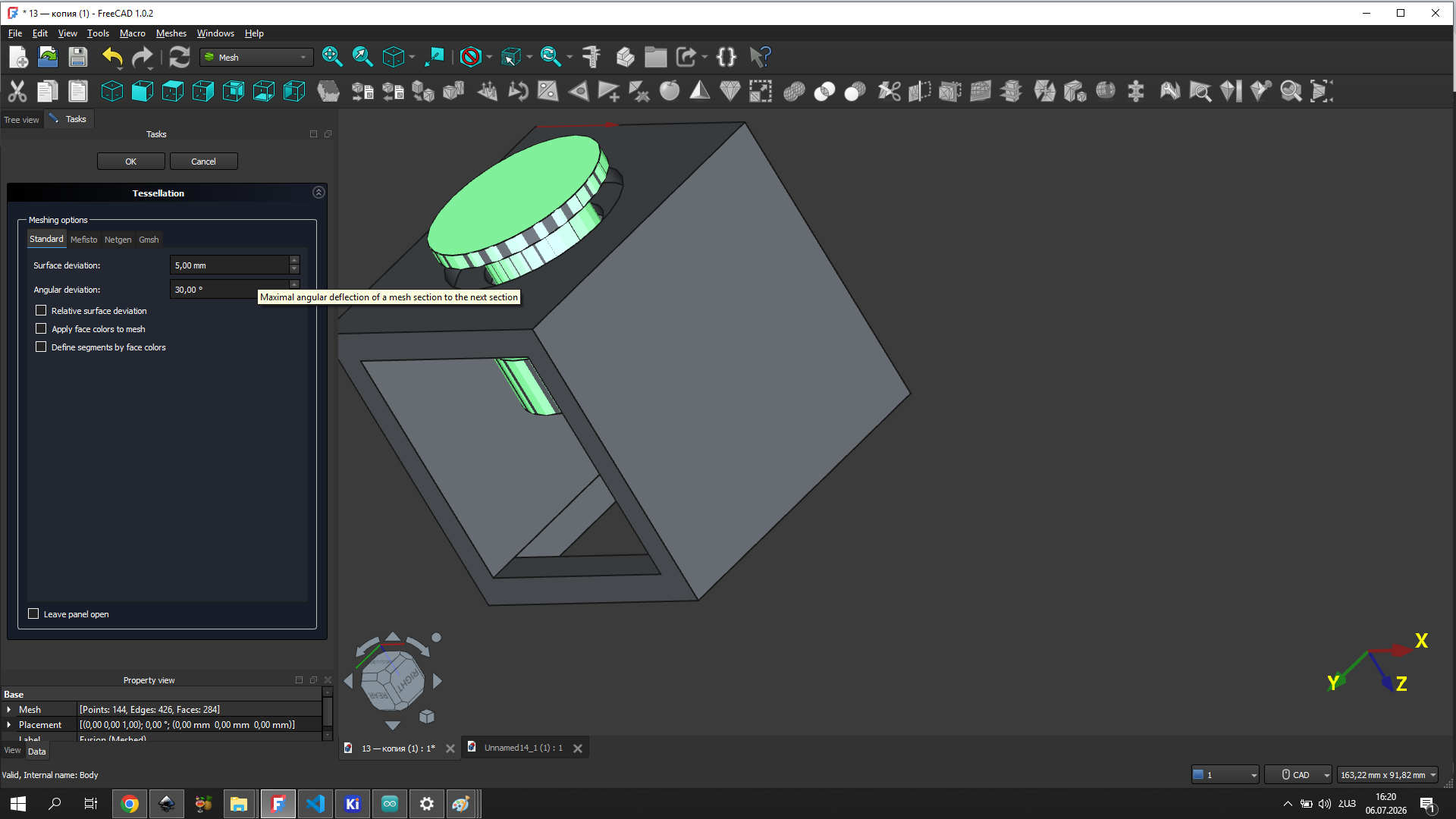
Before exporting, I also experimented with the tessellation settings in FreeCAD’s Mesh workbench to control the mesh quality of the exported model. Tessellation determines how smoothly curved surfaces are approximated by triangles — lower values produce a finer mesh with more detail.
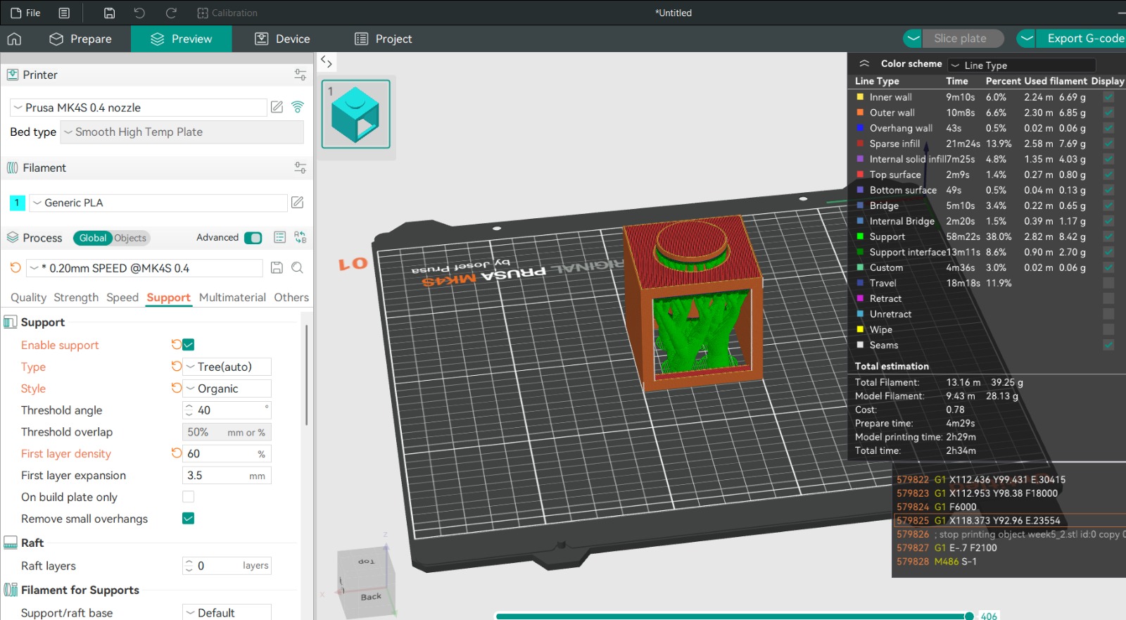
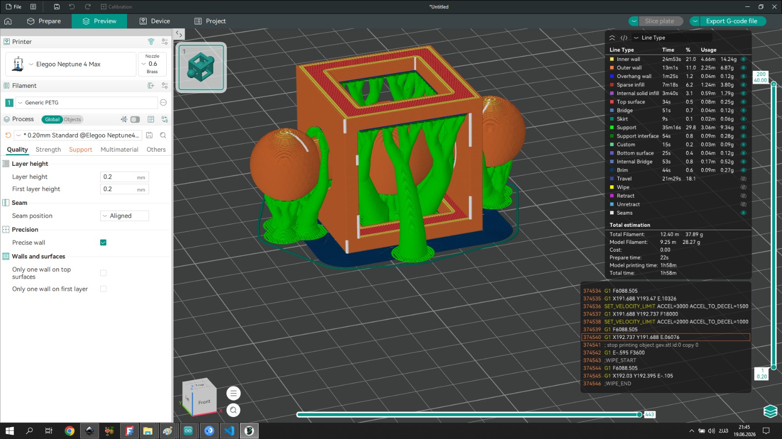
Slicer Preparation
The model was sliced in Orca Slicer using the following settings:
- Printer: Prusa MK4S, 0.4 mm nozzle
- Filament: Generic PETG
- Layer height: 0.2 mm
- First layer height: 0.2 mm
- Print speed profile: 0.20mm SPEED @MK4S 0.4
For supports I used Tree (auto) with Organic style. The threshold angle was set to 40°. Tree supports were chosen because they touch the model at fewer points compared to normal supports, which makes them easier to remove and leaves a cleaner surface — important for a model with curved geometry like the ball-in-cage mechanism.
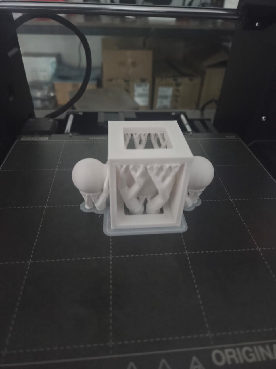
Printed Result
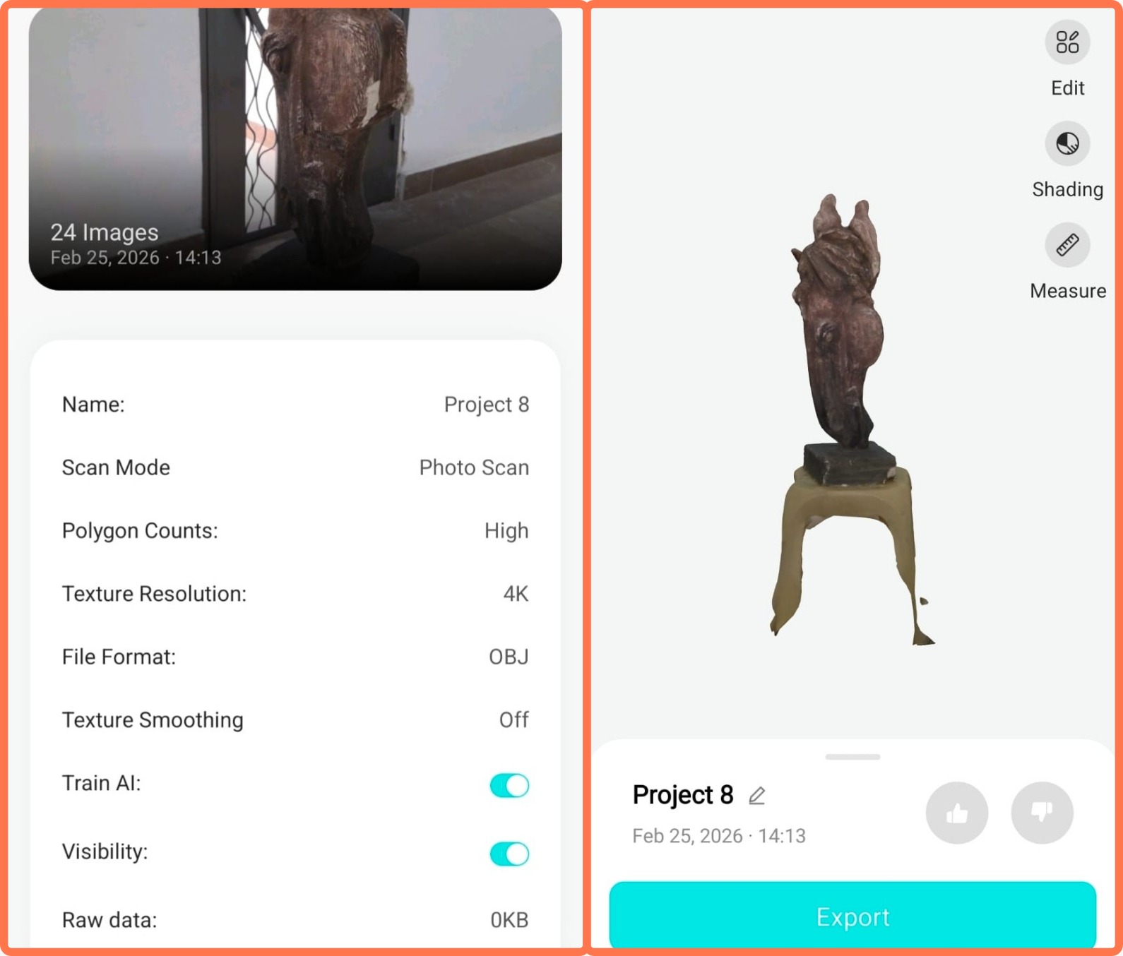
3D Scanning — KIRI Engine
The scanning process was carried out using the Kiri Engineapplication.

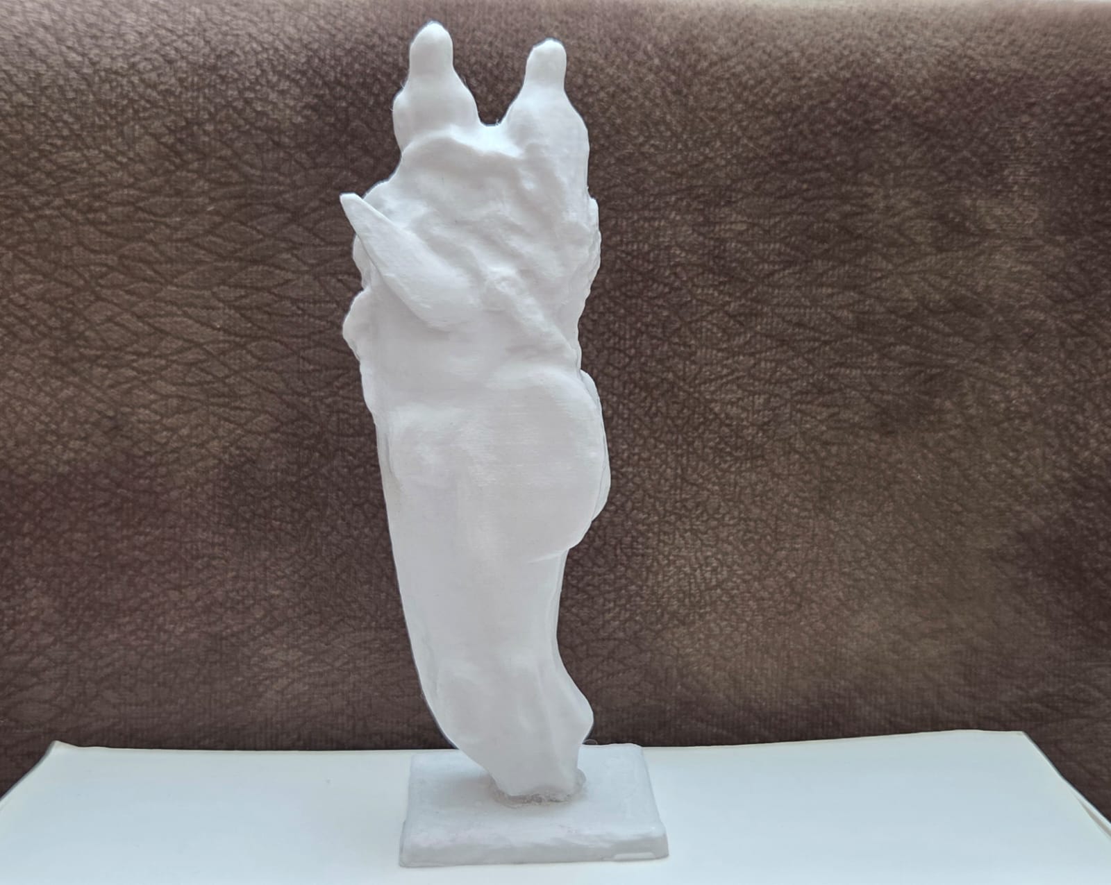
For scanning, I selected a plaster sculpture, which I placed on a chair in an open area with as much free space around it as possible. This position allowed me to move around the object and capture it from different angles, providing enough visual data for the application to generate a more accurate 3D model of the object.
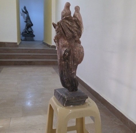
After opening the application, it was necessary to capture multiple photographs of the object from different positions and angles. I tried to capture all parts of the plaster sculpture as completely as possible, including the top, sides, and different perspectives. The variety of photographs was important because it allowed the software to better recognize the object’s shape, structure, and surface details.
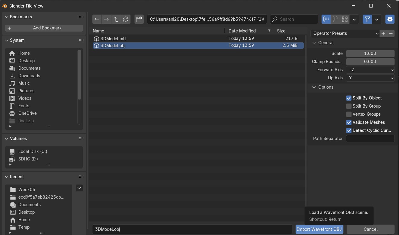
After completing the image capture and processing stage, I saved the generated 3D model in OBJ format. This format was selected because it is widely used in 3D modeling software and allows the preservation of the model’s geometric data for further processing, editing, or use in other digital fabrication workflows.
After that, I opened the Blender software and imported the saved OBJ file. Due to the limitations of the initial scanning process, the imported model contained unnecessary parts and some irregularities, so cleaning and editing were required.
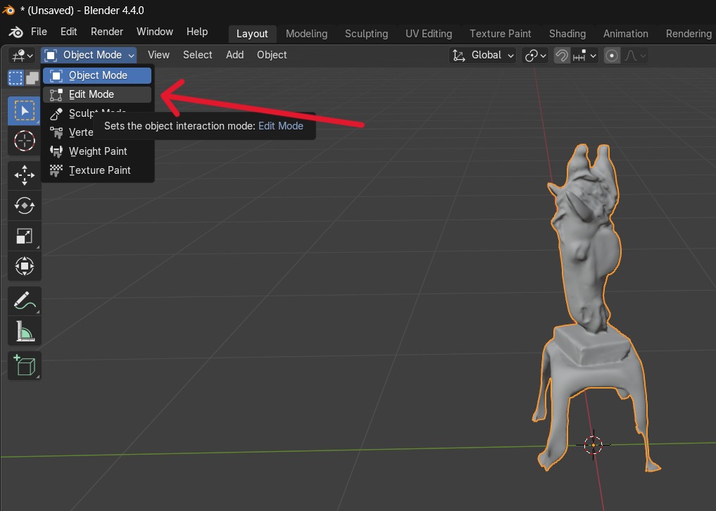
Then, in Blender, I switched from Object Mode to Edit Mode in order to work more precisely with the model’s geometry. Using the vertices**** selection tool,
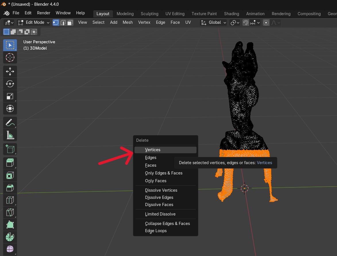
I selected and removed unnecessary parts that appeared during the scanning process. This process helped clean the model, remove unwanted geometric elements, and improve its overall appearance for further use.
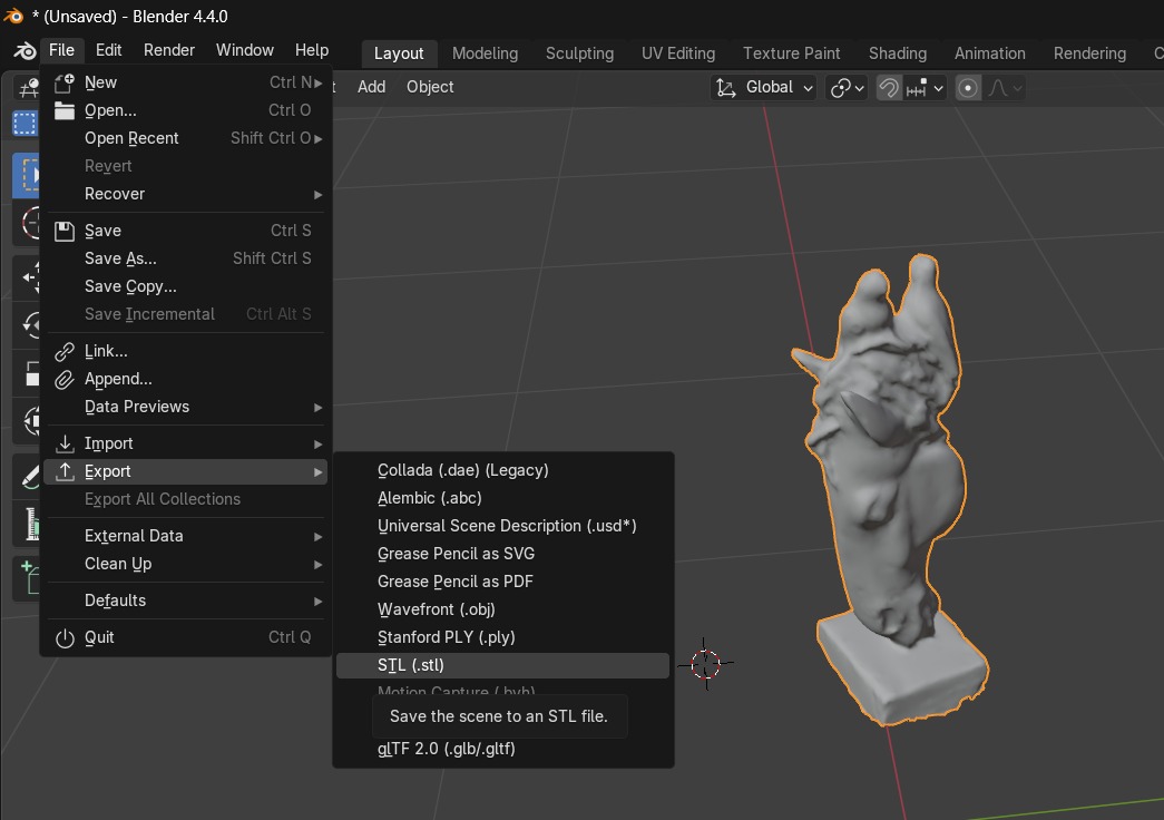
After saving the file in STL format, I opened it in Orca Slicer for further preparation for 3D printing.
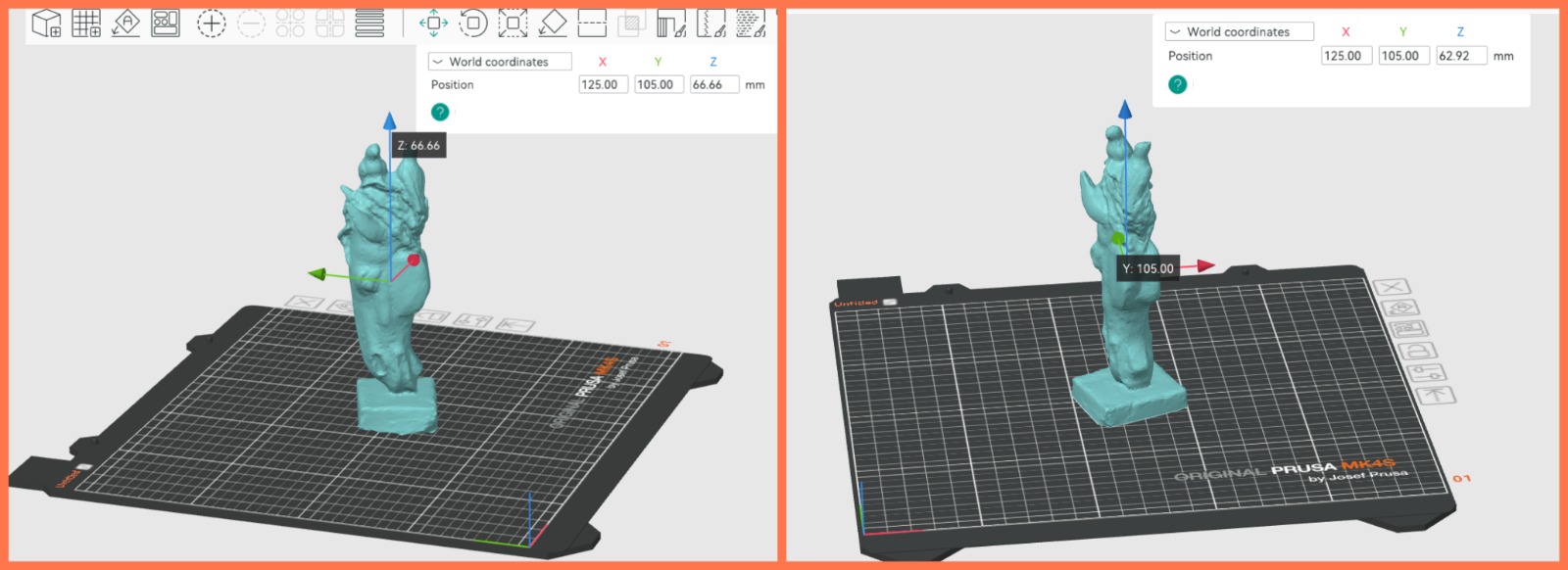
In Orca Slicer, I first adjusted the model’s dimensions to meet the requirements of the printing process. Then, I slightly lowered the model along the Z-axis so that it was properly positioned and fully contacted the build plate. This was necessary because the bottom part of the scanned model was open and did not form a completely closed surface. This adjustment allowed the model to be placed correctly on the printing platform and ensured a more stable 3D printing process.
Next, in Orca Slicer, I selected the printing material: Generic PETG. After selecting the material, I performed the Slice Plate operation, through which the software divided the model into the required printing layers and generated the corresponding G-code. This step prepared the model for manufacturing using a 3D printer.
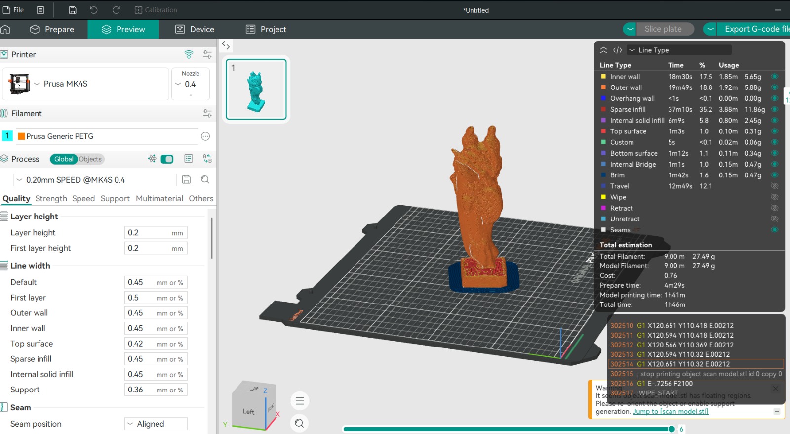
Since the model’s structure did not contain large overhanging or unsupported areas, there was no need to use supports. The model was correctly positioned on the build plate, and its geometry allowed it to be printed without additional support structures. This also helped simplify the printing process and reduce unnecessary material consumption.
Finally, after completing all necessary settings, the file was ready for 3D printing. I saved the model’s G-code file, which contained all the instructions required by the 3D printer, including layer generation, movement paths, and printing parameters. The generated G-code file was ready to be transferred to the 3D printer and used to begin the manufacturing process.
Printed Result of the Scanned Object
After printing, the scanned plaster sculpture was successfully reproduced as a 3D printed object in PETG.