17. Applications and Implications, Project Development
← Back to Final Project: Vahan
What will it do?
My final project is the first stage of a “Smart Workshop” system. The system is designed to continuously monitor air quality in a workshop by measuring the concentration of carbon monoxide (CO) using an MQ-7 gas sensor. Depending on the measured values, the system will automatically activate different warning and safety functions. Under normal conditions, the system will indicate that the environment is safe. When the gas concentration increases, visual and sound alerts will be activated. At dangerous levels, the system will provide clear warnings to help users take appropriate action and maintain a safe working environment.
Who has done what beforehand?
Similar projects have previously been developed by both Fab Academy students and other researchers and engineers.
For example, Fab Academy 2021 student Nicole Bakker developed the “Airable” project, which monitors air quality using a CO₂ sensor and displays the air status through RGB LEDs using green, orange, and red indicators.
Another Fab Academy project, “Plant.Air” by Filipa Silva (2017), was designed to monitor CO₂ levels in indoor environments. The system measured air quality and helped users understand whether the environment was healthy for work or living.
In addition to Fab Academy projects, CO₂ monitoring and automatic ventilation control systems are widely used in schools, offices, and industrial environments. These systems activate ventilation and provide warnings when air quality deteriorates. For example, Sander van Vliet developed a project that combined a CO₂ sensor with a ventilation control system to automatically respond to changes in air quality.
What sources will you use?
The following sources will be used during the development of the project:
- MQ-7 gas sensor datasheet
- Seeed Studio XIAO RP2040 documentation
- RP2040 datasheet
- Industrial safety monitoring system examples (CO/gas alarm systems used in workshops and forges)
- Ventilation and air quality control references (CO₂/CO demand-controlled ventilation systems)
What will you design?
I will design a smart air quality monitoring and safety system for a workshop environment. The project will include a custom PCB, a 3D-printed enclosure, a visual and sound alert system, and communication between electronic modules. The system will measure gas concentration levels, display the air quality status, and activate warning indicators when predefined thresholds are reached.
What materials and components will be used?
The project will use a XIAO RP2040 microcontroller, an MQ-7 gas sensor, a buzzer, LEDs, wires, and connectors. In addition to the electronic components, PCB fabrication materials and 3D printing filament will be used to manufacture the enclosure and mechanical parts of the system.
Where will they come from?
Most electronic components will come from the laboratory inventory or electronic component suppliers. The mechanical parts and enclosure will be manufactured in the laboratory using 3D printers and other digital fabrication equipment.
How much will they cost?
| Qty | Description | Price | Origin |
|---|---|---|---|
| 1 | XIAO RP2040 microcontroller | 6.23 $ | Our Lab |
| 1 | MQ-7 gas sensor | 4 $ | Our Lab |
| 1 | Buzzer | 1 $ | Our Lab |
| 3 | LEDs (Green, Yellow, Red) | 1 $ | Our Lab |
| 1 | PCB board | 9.05 $ | Our Lab |
| - | Resistors, capacitors, headers, and other electronic components | 3 $ | Our Lab |
| - | Wires and connectors | 2–3 $ | Our Lab |
| 1 kg | PLA / PETG filament | 32.99 $ | Our Lab |
| 670 ml | Kapci Base Paint | 70 $ | Local Supplier |
| 1 L | Clear Lacquer | 16 $ | Local Supplier |
| 1 m² | Acrylic Sheet | 18 $ | Our Lab |
| 1 | Metal Sheet | 40 $ | Our Lab |
| Total | ~194 $ |
What parts and systems will be made?
- Gas monitoring system
- Visual and sound warning system
- Emergency warning mechanism
- Custom PCB
- Protective enclosure
What processes will be used?
- Electronic circuit design
- PCB design and fabrication
- Embedded programming
- 3D modeling
- 3D printing
- Laser cutting
- System assembly
- Testing and calibration
What questions need to be answered?
- How accurately can the system measure gas concentration levels?
- How quickly can it respond to changes in air quality?
- Are the visual and sound warnings effective enough to attract the user’s attention?
- How reliable is the warning system?
- How effective is the system in improving workshop safety?
How will the project be evaluated?
The project will be considered successful if it meets the following criteria:
- The MQ-7 sensor accurately detects CO/CO₂ concentration changes within the defined threshold ranges.
- The system responds to gas level changes quickly enough to be useful in a real forge environment.
- The LED indicators and buzzer activate at the correct thresholds — green for safe, yellow for warning, red for danger.
- The enclosure properly houses all components, with sensor openings correctly positioned for airflow.
- The full system operates reliably as an integrated unit, without resets or signal failures during continuous use.
Project Development
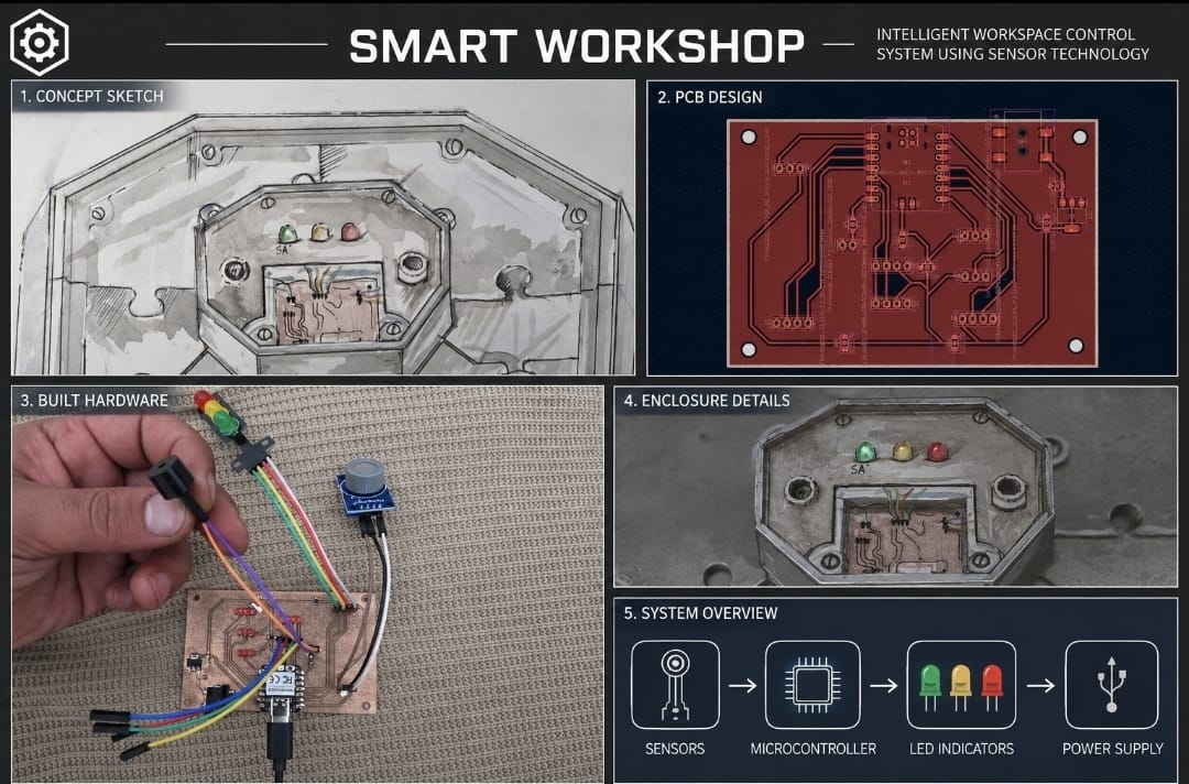
As part of this week’s assignment, I prepared a draft of my final project summary slide (presentation.png, 1920×1080) and a draft video clip (presentation.mp4, 1080p HTML5, under 1 minute, under 25 MB). Both are placeholders at this stage and will be refined as the final project nears completion. I placed both files in my root directory and checked that they are correctly linked in the final presentation schedule.
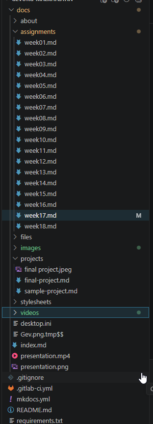
Uploading the files
After preparing the placeholder slide and video, I uploaded them to the root of my website using the required filenames, presentation.png and presentation.mp4. Since my site is built from Markdown with MkDocs, this meant placing both files directly in the docs directory. This lets the Fab Academy presentation system correctly detect and link them.